Electrical Wiring for a TBucket


Mathieu,

Many thanks for the offer to build an adapter to make the AQ-1 log MPH, but
like you say it should work. I hope that it won't be a problem.

Maybe logging MPH won't be important to understanding what's going on inside
the engine and maximizing output. But it still would be interesting.

 
I dont know if your new to Alan w2aew channel on youtube(the video you posted is from him) if you did not already subscribe to hes channel you should :).
Am subscribed to that channel since quite a bit of time now, tons of usefull video, and new video pretty often. We(me and w2aew) are also on the Amateur repair yahoo group(this one is for ham radio). Really a nice guy, answer question and will take video request too :). To me he is the best teacher on the net.
 

No it's a GPS speedometer. I went this direction so I would have a lot more
functionality like shown below. Especially the 1/4 mile and 60 foot times.


Attachments

  • FP01_SpeedHut_SpeedoDigitalDisplay.jpg
    FP01_SpeedHut_SpeedoDigitalDisplay.jpg
    55.5 KB · Views: 54

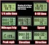
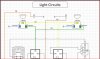
Keeping with the theoretical to physical conversion of the drawings.......

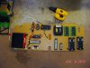
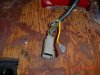
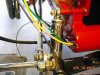
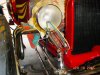
Some of my components mounting holes are under neither the seat back cushion
making it hard to tighten screws back there as you can see from the photo below.


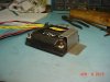
So I made this bracket to pin the back side of the AQ-1 while I use the two front
screws to finish the mounting. I will mount the bracket before I slip the 1/4 inch
plate into place with most components and bracket already mounted. If needed I
can easily remove the AQ-1 by itself without removing the entire plate. Might
consider more brackets, time will tell.


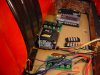
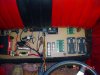
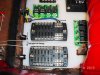
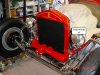
I'm using a 1/4 inch Acrylic plate for mounting, instead of going direct to the floor.
The advantage is drill and mounting components while in FULL view and laying on
the floor for best access. This is where I'm at now with the right side (battery side)
almost finish mounting, notice the screws holding components in place. Still thinking
and circling the left side, there might be some changes !!!


Cost of the Acrylic plate was $30.


Attachments

  • FP11_AQ1Bracket_6030.jpg
    FP11_AQ1Bracket_6030.jpg
    84.5 KB · Views: 49
  • FP11_AQ1Bracket_6031.jpg
    FP11_AQ1Bracket_6031.jpg
    118.4 KB · Views: 49
  • FP11_ComponentDrilling&Mounting_6037.jpg
    FP11_ComponentDrilling&Mounting_6037.jpg
    130.2 KB · Views: 49
  • FP11_ComponentLayout_6034.jpg
    FP11_ComponentLayout_6034.jpg
    109 KB · Views: 49
Mmmmmm - man I really am itching to work on another project! Gorgeous! ...and inspiring.
 

Thanks Dorian!!!

What do you think your next project will be after the KG is running again?

 
Indycars said:

Thanks Dorian!!!

What do you think your next project will be after the KG is running again?


Honestly not sure... but I do know that I want to take my sweet time to build it. I still went a little fast on the Ghia. The next one will be inspired by the work I am seeing here. Every little detail will be carefully minded
 
DorianL said:
Indycars said:

Thanks Dorian!!!

What do you think your next project will be after the KG is running again?


Honestly not sure... but I do know that I want to take my sweet time to build it. I still went a little fast on the Ghia. The next one will be inspired by the work I am seeing here. Every little detail will be carefully minded

i cant wait... you guys all make me want to do better just to try to catch up with the level you work on. thumbs up
 
There are some stunning things here... my next project will require me to learn how to weld ;-)
 

I'm using solid pins and sockets, that seem to be the same size on the mating
ends. They have the same insertion force and are within less than .001 inches
of diameter of each other. The only difference is the size of wire that can be
crimped in the barrel. So my take on this is either size pin will work will with
either size socket within the same connector

I'm using the DT series of connectors, you know the same ones that NASCAR
uses. Or so I've read anyway.


Here is a video to show how the connectors are assembled. I could take photos of
every step, but the video shows it much better than anything I can do.

https://www.youtube.com/watch?v=LIR9-ZdG958


This is what I ended up with, the yellow wire is 12 gauge and can't go thru the
DT connector.


I bought these crimpers and so far they have worked perfectly....very happy with
them. Plus I only need one of them for most of my work, it does all three sizes of
14-16-18 gauges. The second crimper does 20-22 gauges, which I don't use in my
car's wiring. Much less wondering where in the hell I put that tool, it was just in
my hand 15 seconds ago.

http://www.toolaid.com/content/deutsch- ... ervice-kit
http://www.amazon.com/dp/B00A6AS55Q/ref ... ords=18650


Attachments

  • FP12_DeutschConnectorAssembled_6047.jpg
    FP12_DeutschConnectorAssembled_6047.jpg
    122.3 KB · Views: 15
  • FP12_DeutschPin_6042.jpg
    FP12_DeutschPin_6042.jpg
    73.6 KB · Views: 15
  • FP12_DeutschPin_6046.jpg
    FP12_DeutschPin_6046.jpg
    56 KB · Views: 15
  • FP12_ToolAidCrimper.jpg
    FP12_ToolAidCrimper.jpg
    69 KB · Views: 15
mathd said:
Hehe, and the fun begin :).
keep us posted :!:

Your wish is my command!!!!!! :D

I've been pulling wires thru the frame after drilling two 3/4" holes right under the
headlights. I'm running separate wires up each side of the frame to the headlights,
when I could run up one side and then cross over to the other side with a parallel
circuit for the other side. Also I'm running grounds all the way back to the fuse
panel in stead of using the frame. IIRC .....Steel has about 10 times the resistance
of copper.

I ran 12 gauge wire to the headlights, but the three wires would not fit thru the hollow
bolts that feed the headlight bucket. I started drill with 9/32 inch bit and ended with
11/32 inch bit before three 12 gauge wires and heat shrink would fit thru the hollow
bolts. I think the bolt is still substantial enough to hold up to driving. I guess most
people run 14 or 16 gauge wire to the headlights.


Added labels to each wire inside the headlight bucket. On the back of each headlight
is a Sharpie label to match, therefore only an idiot like me could get it wrong


Same headlight wires where they come into the relays under the seat.


I'm updating the wiring schematics as I run the wires to reflect the color and
size of wire.


Attachments

  • FP01_HeadlightSchematic.JPG
    FP01_HeadlightSchematic.JPG
    81.5 KB · Views: 8
  • FP01_HeadlightUnderSeat_6056.jpg
    FP01_HeadlightUnderSeat_6056.jpg
    136.5 KB · Views: 8
  • FP01_HeadlightWireLabels_6058.jpg
    FP01_HeadlightWireLabels_6058.jpg
    115.8 KB · Views: 8
  • FP01_HeadlightWiring_6050.jpg
    FP01_HeadlightWiring_6050.jpg
    136.3 KB · Views: 8
  • FP01_LabelsOnHeadlights_6060.jpg
    FP01_LabelsOnHeadlights_6060.jpg
    123.3 KB · Views: 8
  • FP01_HeadlightHollowBolt_6061.jpg
    FP01_HeadlightHollowBolt_6061.jpg
    140.7 KB · Views: 8
12 gauge seem big but since your battery is a bit more in the back and you use longer wires i think 12ga is great.
You want to reduce the voltage drop as much as posible with relays and headlamp(keeping wire short or big).

Am a big fan of labelling relays and wires, no problem with that.
am using this:
brother-labeler.jpg
 

I found I needed to put clear shrink over the labels to secure them. After 10
minutes I could see the edges of the labels lifting.

What have you experienced, maybe I need a different label material ???

 
Indycars said:

I found I needed to put clear shrink over the labels to secure them. After 10
minutes I could see the edges of the labels lifting.

What have you experienced, maybe I need a different label material ???

After 4 years its still holding on :).
I don't know what material it is sorry. the label casette/reel come in different grade of glue.
 

Can you post some pics of how you do your labels, nothing to elaborate. Just one
or two pics ..... please.

 
Well, this is not a picture of mine but for wires and cables i set them like this(back to back, like the red one below):
ptedge_app_cable_wire_sm.png

or like this since its the same size am using:
iu

I don't think they will come off.
When i set them on relays etc.. i clean the surface before, usually with some solvent. No problem.

Also, when i got my Brother labeler, the included label casette was very thin glue grade, they dont hold up very well and are not very long too!.
When i got a new labeler casette(with better grade glue) from the store, it was night and day.
 
Back
Top