engine assembly check list

grumpyvette

Administrator
Staff member
read the linked info theres a ton of valuable tips and facts
I know some of you guys would rather pluck your eye out with a red hot fork, rather than read links and sub links but for the few who want to learn...
When having a machine shop do any work, always ALWAYS get everything in detailed writing before you start,
specifying all machine work, to be done in detail,list parts and labor costs, mandate a delivery due dates and have every single part you supply ID stamped, and photographed, have all the work too be done and parts individually listed and a value assigned, with both YOU and the machine shop having identical signed copys
listing the cost and dates and work details

12cal.jpg

I takes time to learn the skills and you need to do research any time you are not 100% sure you know whats required, if your a first time engine builder that will damn near be everything you touch,by the time you buy the minimum tools required and a few books for research, and total up the local machine shop labor charges , youll most likely find the price of a crate engine looks much more reasonable, to think you know everything you need to know on the first few engine builds is absurd, thats about like If I offered to charge someone $3000 to build them an engine.
allowing them to watch , so they see how its done,
and then expecting them to have identical skill,
and have the tools collected over a lifetime , and the knowledge, of how the tools are used and why its required,
even if that particular engine I build never needed them!
at the end of a couple weeks!
easily 70% of the skill involved, is in knowing what to look for,
and recognizing what needs to be corrected ,
what components are ok as they are,
and what needs major machine work,to function correctly,
what should be pitched in the trash and replaced ,
and what can be modified and used!
and because that varies with every engine,
it takes experience and time to gain those skills, and know what to look for ,
some thing you gain over time making mistakes and being forced to do research,
that you would not gain in a couple weeks time,
and something requiring you to spend a few years getting your hands dirty in the process of learning.

http://garage.grumpysperformance.com/index.php?threads/finding-a-machine-shop.321/#post-55314

http://garage.grumpysperformance.co...it-in-writing-dated-signed-and-pictures.4786/

http://garage.grumpysperformance.co...embling-an-engine-correctly.10363/#post-43806

http://garage.grumpysperformance.co...et-for-tracking-your-machine-shop-costs.3423/

http://garage.grumpysperformance.com/index.php?threads/machine-work-costs.3169/#post-8452
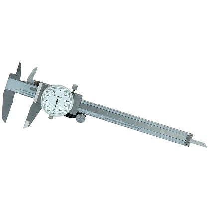
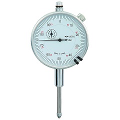
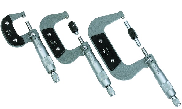
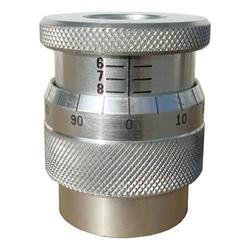
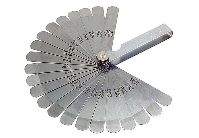
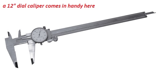
you'll
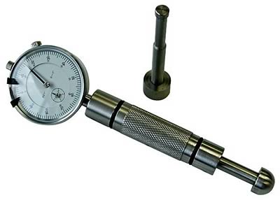
need accurate precision measuring tools

http://garage.grumpysperformance.com/index.php?threads/precision-measuring-tools.1390/

http://www.superchevy.com/how-to/4567-chevrolet-big-block-engine-generations/


viewtopic.php?f=53&t=2726

viewtopic.php?f=53&t=852


viewtopic.php?f=53&t=509

viewtopic.php?f=53&t=4690

http://www.technovelocity.com/chevyhack ... cation.htm

viewtopic.php?f=53&t=619

viewtopic.php?f=53&t=5478


viewtopic.php?f=52&t=82

http://arp-bolts.com/pages/technical_installation.shtml

viewtopic.php?f=50&t=2920

viewtopic.php?f=27&t=1018

viewtopic.php?f=52&t=181

viewtopic.php?f=52&t=90

viewtopic.php?f=52&t=5078&p=14433#p14433

viewtopic.php?f=52&t=399

viewtopic.php?f=52&t=401

viewtopic.php?f=50&t=501

viewtopic.php?f=54&t=2187

viewtopic.php?f=53&t=247

http://www.youtube.com/watch?v=aATDsYVV ... re=related

http://www.animatedengines.com/otto.shtml

http://www.mustangandfords.com/techarti ... c_oil.html

http://www.rehermorrison.com/rmEngineBook.htm

heres a few things that should always be checked on an engine build , IN NO PARTICULAR ORDER , HOPEFULLY FORCING YOU TO READ AND ORGANIZE THEM YOURSELF
the assembly check list


--------------------------------------------------------------------------------

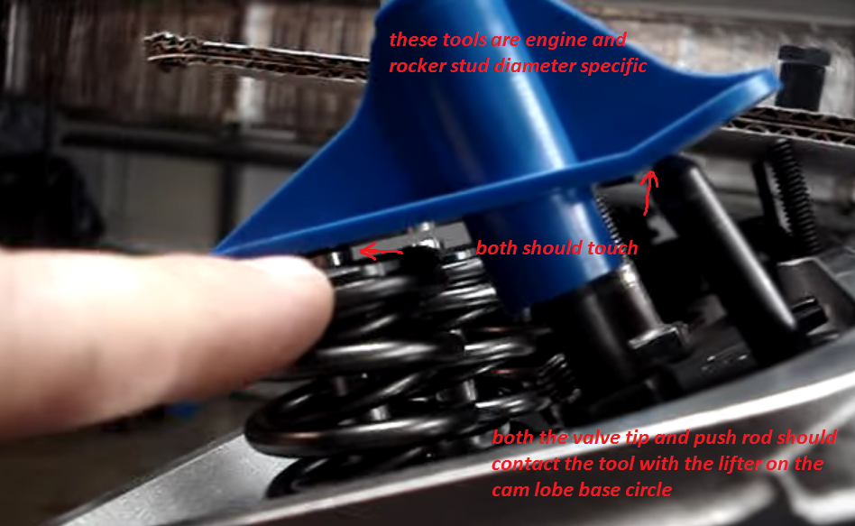
be sure you check clearances carefully, a mistake can and will damage the engine, DON,T GUESS<KNOW WHAT THE CLEARANCES ARE, ESPECIALLY SPRING BIND,VALVE TO PISTON,ROCKER TO ROCKER STUD, and retainer to valve guide clearances I still use the strips of modeling clay about 1" square and .2" (two tenths thick) but one thing everyone forgot to mention so far is that you need to spray the piston and valve and clay strips with WD-40 to ensure the clay does not stick to any parts, otherwise the clay will tend to stick to the valve and piston allowing them to push the clay between them during the compression of its surface by the valve (exactly what its there for) and PULL ON THE SURFACE of the clay as the valve moves away during separation (because the clay tends to stick ever so slightly as the parts pull away from each other if you don,t)which tends to give a false slightly greater than correct clearance measurement
most people tend to tell me Im wrong about that until they try it both ways :grin: yeah the difference is usually minor but five to 10 thousands difference is not rare if the parts are clean and dry versus sprayed with an oil mist first check to make sure that you are measuring correctly, many times the valve actual has more clearance in the fly cut clearance notches,or only the very edge of the valves head and the edge of the notch are close and very minor cutting with a tool fitted in a valve guide will clear the problem and the valve has more clearance than measurements taken from the pistons upper surfaces, and that the head gasket thickness and valve train geometry are correct,
check if changing the cam retard/advance or installed position can be changed to increase the clearance to 0.100 minimum on both the intake and exhaust valves (MOST LIKELY TO WORK WITH THE LEAST PROBLEMS)
remember, you don,t generally do a single pre-assembly check, but a series of repeated checks, as each component is added ,making sure its not going to cause problems or require custom fitting and clearance work
During the early pre-assembly tests,I don,t usually use any rings installed during some measurement checks
(like) rod to block rail, clearance checks,where use of an old set of used but good rod bearings(cleaned and well lubed) and rocking the piston in the bore will work, or finding TDC, but I recheck exactly as it will run during later, pre assembly's, checking clearances/geometry, and the final assembly
__________________

add a thicker head gasket? ( BUT THAT TENDS TO RUIN QUENCH AND DOES NOT TEND TO BE A GREAT CHOICE ON MOST ENGINES)

look over the isky site they and MANY OTHER HOD ROD TOOL SUPPLY SHOPS SELL TOOLS THAT APPEAR TO BE EXTRA LONG STEM VALVES WITH CUTTERS ATTACHED TO FIX THAT PROBLEM
http://www.iskycams.com/pdfcatalog/PAGE17.pdf


heads
are the push rods perfectly strait?
do the push rods flow oil?
rocker studs/guides torqued correctly?
do the head bolts have washers under the bolt heads? are they the correct length for the cylinder heads in use?
have the heads been pocket ported?
have the combustion chambers been un-shrouded?
intake ports gasket matched"
are the valve guides cut to the correct length?
are the heads pocket ported?
is the retainer to valve guide clearance correct?
are the valve guide oil seals installed?
is there valve spring seats installed?
inner damper springs installed?
spring bind height checked? (to exceed max valve lift by .050 min.)
oil return holes cleaned of casting flash?
were steam holes in heads necessary?
were the spark plug threads of a installed spark plug extending into the combustion chamber?
rocker slot to rocker stud clearances ?
retainer to valve guide clearances?
spring bind height checked for the correct spring pressure?
valve lash/pre-load ?
are the valve springs the correct tension,height?dia.
keeper the correct angle? style? size?
valve seats the correct angles?
valves back cut?
valves the correct length, stems the correct diam.
strait?
rockers the correct ratio?
were the valve to valve guide clearances checked?
were the heads milled?
did the head gasket overlap the bore?
what are your valve train clearances?
is the rocker arm geometry correct!
chambers CC,ed
port work..(some steps optional)

(1) open throat to 85%-90% of valve size
(2)cut a 4 angle seat with 45 degree angle .065-.075 wide where the valve seats and about .100 at 60 degrees below and a .030 wide 30 degree cut above and a 20 degree cut above that rolled and blended into the combustion chamber
(3)blend the spark plug boss slightly and lay back the combustion chamber walls near the valves
(4)narrow but don't shorten the valve guide
(5) open and straiten and blend the upper two port corner edges along the port roof
(6) gasket match to/with intake and raise the port roof slightly
(7) back cut valves at 30 degrees
(8) polish valve face and round outer edges slightly
(9)polish combustion chamber surface and blend edges slightly
(10) remove and smooth away all casting flash , keep the floor of the port slightly rough but the roof and walls smoothed but not polished.
(11) use a head gasket to see the max you can open the combustion chamber walls
(12) blend but don,t grind away the short side radius


block
is the oil pump pick-up mounted 3/8"-1/2" from the oil pan floor/
is the windage screen mounted about 1/8" from the rotating assembly/
is the pick-up brazed to the pump body?
has the oil pump relief piston in the oil pump been checked for free ,easy movement? clearance? spring tension?
is the oil pump pick-up tube inserted too far into the oil pump body,(binding the gears)
has the block been clearanced for the rotating assembly?
has the block been line honed?
is the crank strait?
are the damper install key way and threads ok?
counter weights clearanced?
MAGNAFLUXED?
OIL PASSAGES CLEANED?
GALLERY PLUGS INSTALLED CORRECTLY?
has the cam to rod bolt clearance been checked?
piston to valve clearances checked?
piston to bore clearances?
TRUST BEARING CLEARANCE?
what were the piston ring to slot clearances?
RING GAPS?
were the rings all checked individually for end gap in the cylinders they were used/installed in?
were the rings checked to make sure the correct side faced up, and the correct ring was in each groove?
what were the back clearance on the rings?
were the oil ring expander carefully fitted for correct drag?
were the oil ring scraper ring rails checked for end gap?
total cam lift and remaining clearanceS?
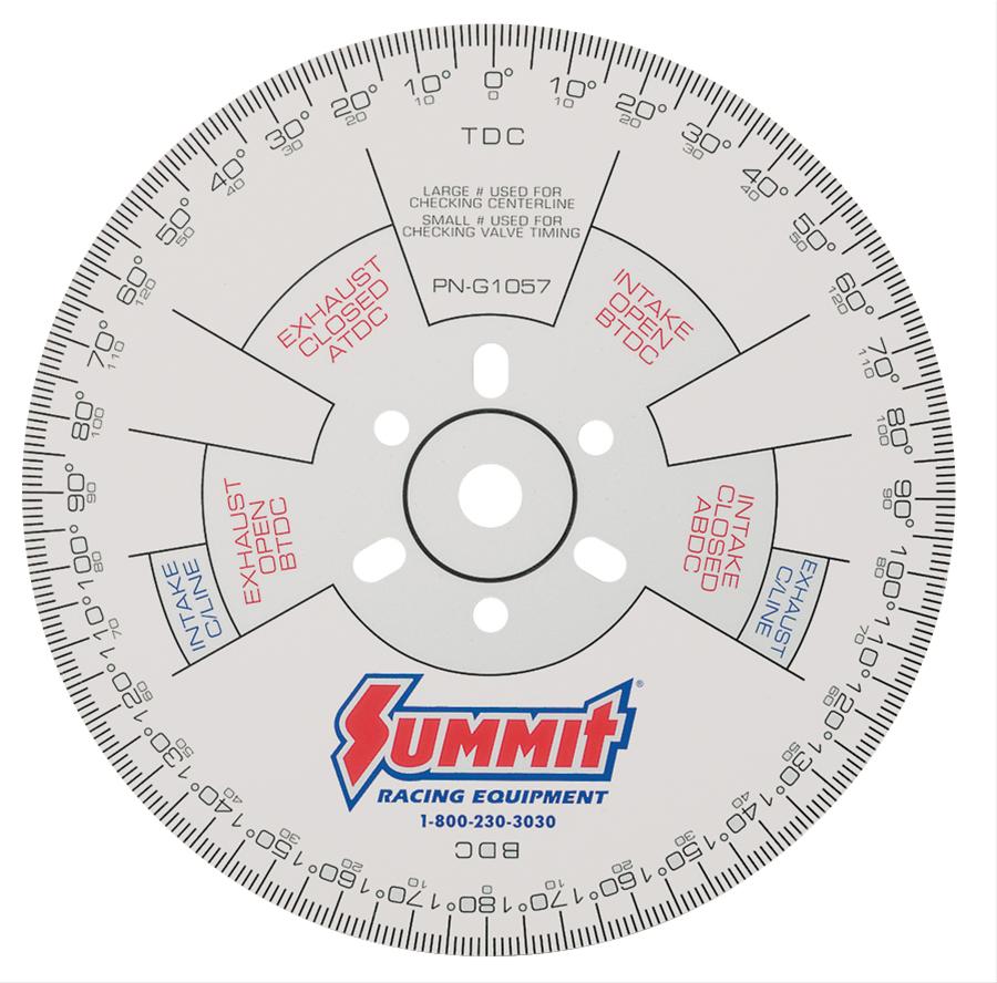
WAS THE CAM DEGREED IN?
main bearing clearances?
what is the main bearing run-out clearance
piston to head clearance? (QUENCH?)
head gasket to coolant holes checked?
magnets installed?
rod bolt to block clearances?
what tq reading is necessary to spin the crank with no rods attached?
are the rod bolts and main caps torqued correctly? (rod bolts checked with a bolt stretch gauge?)
did you check the block for a strait main cap alignment?
what size journals and what were the bearings edge to filet clearance??
are the journals checked for finish and run-out/tapper?
did you use moly lube to assemble?
correct bearing crush?
did you pre-lube before start-up?
did the distributor gear fit the cam gear precisely?
was the distributor oil flow mod done?
was the correct style distributor gear used?
did you check the piston to piston pin bores for fit and clearance?
did the piston pins to snap ring clearance seem overly tight?
if they are pressed pins were they correctly matched and checked for free movement in the pistons?
was the engine balanced?
cam button installed?, and lock plate installed?
were the rods re sized? checked for parallel bores/were the rods strait?
piston valve clearance notches correctly located on the pistons? edges smoothed?
were the rods checked for length?
is there a few thousands clearance on the oil pump drive shaft AFTER the distributors bolted down?
did you install a steel collar on the oil pump drive shaft?
was the rod to piston pin side clearance checked? (at 4 places separated bye 90 degree spots)
does the oil pump drive shaft mid section clear the block with the pump installed?
whats the starter to flywheel gear clearance?
is the pilot bearing to trans imput shaft clearance ok?
is the front motor mount bolt to fuel pump pushrod clearance ok? did the fuel pump pushrod move easily/
are you possitive the pistons were installed with the correct valve relief in the correct location?(eiieeiie) were the pistons installed with the correct side facing forward/
what torque values were used on all fasteners/ were they the correct length and type bolts?
were the bores honed with a torque plate in place?
was the cylinder finish correct for the type rings used?
was the oil pump itself checked for free spin and clearance AFTER THE PICK-UP WAS INSTALLED?
was the cam drive checked for free rotation and drag/
were the oil passage plugs drilled for extra oil flow?
were the lifter bores checked?
cam to timing cover clearance?
cam journal to cam bearing clearances?
was the cam journal run-out checked?
was the cam degree in or just lined up using factory index marks?
has the rod and windage screen to oil pan clearance been checked?
does the dipstick & tube clear the windage screen?
was the cam lobes/LSA/LIFT CHECKED?
is the deck square/level?
whats the cross hatch hone angle?
what grit hone was used? is it correct for the rings used?
are all the threads clean/clear?
brass freeze plugs installed?
block painted?
a few things to check

are the connecting rods installed with the beveled edge facing out on each pair with the bearing installed with the bevel facing out on both the lower and upper rod bearings also?

are you using beveled bearing shells that match the cranks throw bevels?

what are the bearing clearances? (are they the same checking at 90.120.160 degrees from the first measurement?}

what are the connecting rod side clearances?

is the crank strait? has it been turned undersized? if so...on ALL the rods? on ALL the mains? or on ALL the BEARINGS JOURNALS OR ONLY SOME?

whats the TRUST BEARING CLEARANCE?

is the piston side clearance correct?

are the pistons installed in the correct cylinders? (intake and exhaust notches correctly located to match the cylinder head)

are you POSITIVE each main cap is in the correct location and FACING THE CORRECT DIRECTION?

did you use MOLY assembly lube?

did you check EACH INDIVIDUAL RING ON EACH PISTON for ring gap clearance,AND that the rings fit the piston ring slots correctly? are any rings installed in the wrong ring slots (2nd ring in top slot ETC,)or upside down

do the rings have back clearance?

were the cylinders CORRECTLY HONED?

is the cam drive binding?

does the crank contact the windage screen?
does the dipstick tube or dip stick touch the crank at any point?

is the oil pump /cam gear binding?

did you check that the oil pump mounting bolt does NOT contact the back surface of the rear main BEARING under the main cap?

is the block warped, checked carefully?,was it line honed?


are the piston pins centered? do the pistons rotate thru an arc with little resistance?

are there any lock pins, spirolocs, tru-arcs contacting the cylinder walls?

are you sure the bearing shells are installed correctly and the locating tabs are in the correct slots?
are they the correct bearings for the application? or did you just assume the part guy knew what he was doing?
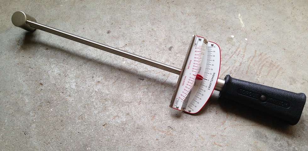
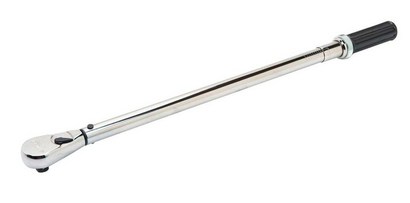
did you MEASURE or GUESS, did you at least use Plasti-gauge and a torque wrench?
distriboil.jpg


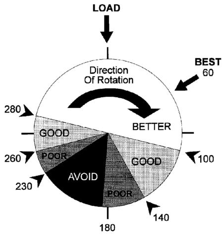
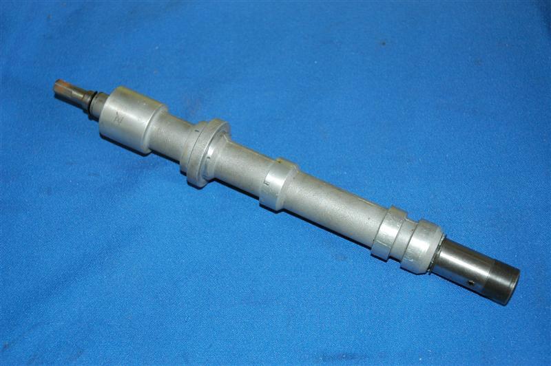
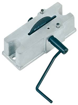
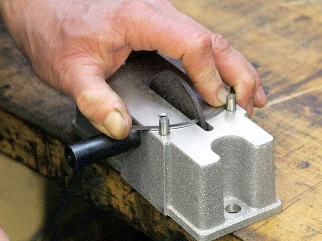
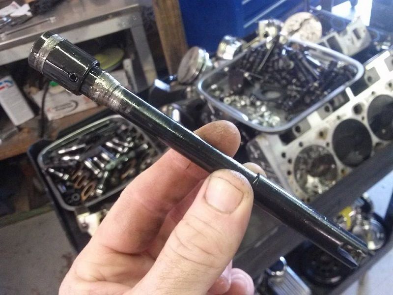
on Chevrolet engines, Crane recommends that a .030-inch-wide and .030-inch-deep groove be machined or filed into the bottom band on the distributor shaft as shown (arrow) to provide lubricant to the distributor gears. Place the groove on the distributor so that when timed properly, the groove will face the camshaft. With the distributor in this position, oil will spray both the distributor and the cam gear to significantly reduce gear wear. This trick can improve gear life for any type of camshaft. Ford engines have an oil passage plug that points directly at the distributor gear. A .025-inch hole can be drilled into the plug to lubricate these gears.

did you check EACH AND EVERY journal for tapper and roundness

did you get the rotating assembly balanced???
watch the slide show linked below for more tips

http://www.alteredwheelbasenova.com/the ... art_1#Next

http://www.alteredwheelbasenova.com/the ... art_2#Next
 
Last edited by a moderator:
when, your test fitting components,and you find some part that does not fit as designed, STOP!
FIND OUT WHY THE PART DOES NOT FIT,ASK QUESTIONS ,MAKE A FEW PHONE CALLS!
AND CORRECT THE SITUATION BEFORE PROCEEDING!
Ive been building engines for over 40 years now, eventually even my hard head learned
rule one
read the manufacturers instructions carefully and call the tech guys if ANYTHINGS not 110% clear
RULE two
IF something won,t fit or function....STOP, call the the tech guys after you re-read the manufacturers instructions carefully and measure carefully so you sound at least 1/2 way like you know what talking about, then call the tech guys if ANYTHINGS not 110% clear

RULE three
STOP AND DO THE REQUIRED RESEARCH if youve got questions
I never mind sounding dumb as long as I get the correct answers, so I won,t LOOK dumb by doing something wrong
don,t skip over it or skip steps or over look the little things ,don,t get crazy,its not personal, it might be as simply as a badly heat treated distributor gear ,the lifter bore needs honing, the rings need gaping, there's a bit of clearance that needs to be ground to allow clearance, etc. a badly machined intake or distributor main body, you need to check things like the piston dome to combustion chamber clearances , rod side clearance, thrust bearing fit etc. valve train geometry, spring load rates,or indications of significantly less oil than required reaching the cam,gear teeth, lifters, connecting rod bearings or check if the blocks a bit distorted or machined incorrectly, match the next cam to the distributor gear the cam manufacturer suggests and cut the extra shallow oil feed groove in the the block wall of the distributor vertical shaft ,so there's a constant spray of oil into the gear mesh location, then remember to drill the .030 hole in the pass side oil gallery plug behind the cam gear and verify the rods clear the block and windage tray, for example then when you install the cam timing set ,before you install the chain, do a test assembly and install the intake and heads temporarily and spin the cam and distributor by hand looking for binding or mis- alignment issues.
just be logical and test clearances etc. during the testing &b /sub assembly stage of the build up.
you probably need to check/assemble a block at least a half dozen times at a MINIMUM to get the clearances near correct.
sure theres guys that just bolt all the pieces together and have engines that run, but those guys seldom have engines that last nearly as long or put out nearly the same power as the guys that make the effort on ALL the little detail and clearance work.


KNOWING WHAT YOUR DOING IS IMPORTANT, TO GETTING GOOD RESULTS!
no one knows everything about all models and years so it helps to have the correct procedures and info in a handy referace source,now you can get by with a HAYNES or CHILTONS manual, or something similar, but for detailed info, OWNING the CHEVY SHOP MANUAL FOR YOUR SPECIFIC CAR IS ALMOST MANDATORY!
I get asked frequently, "how did you know how to do that?"
well, EXPERIANCE plays a big roll, working on similar cars and engines helps, and the INTERNET is a good resource... but theres ALWAYS a big need for DETAILED REFERANCE MATERIAL, SPECIFICALLY MATCHING YOUR PARTICULAR CAR and if you have not yet invested in a SHOP MANUAL for the year make and model of you pride and joy muscle car your either not serious about your hobby, or most likely NOT A SERIOUS HOT RODDER! I constantly see guys SCREWING up installations, or adjustments,if you don,t know exactly what your doing, you need to either let the dealer do it and PRAY his mechanics are experianced and can read, OR..if your like ME, you would rather do it yourself and KNOW its been done correctly...
if your not aware, heres where to order them....

1-800-782-4356

http://helminc.com/helm/homepage.asp?r=

your average shop manual may cost $100-$150 ONCE! but youll easily save far more than that in reduced time and screw ups in under a years time or in many cases on one job vs having the dealer do the work!

BTW
IVE dunked my piston/ring assembly's in a can of MARVEL MYSTERY OIL just before installation with a ring compressor and have never seen the slightest indication of problems either on ring sealing getting the rings broken in, or on tearing the engines down later for inspections

remember that when you go to re-install the compressed piston rings, and piston in the engine block,bores that dunking the piston in MARVEL MYSTERY OIL , just before, its slid into the ring compressor will coat the rings and bore contact areas enough to prevent many small problems that insufficient lube might case
 
viewtopic.php?f=44&t=700&p=1095&hilit=+sealant#p1095

sealant info worth reading thru in the above link

http://www.rehermorrison.com/rmEngineBook.htm

books you need in the links below for the bbc

heres a good source for SBC info
http://www.themotorbookstore.com/resmchstvi.html

this book includes a CD you can watch with a great deal of useful tips and info
the book and CD are one of the best basic sources of info IVE found for new guys


http://www.amazon.com/How-Rebuild-Your- ... 671&sr=1-2

http://www.amazon.com/Big-Block-Chevy-E ... g_b#reader

http://www.amazon.com/Hotrod-Chevy-Hp42 ... b_3#reader

http://www.amazon.com/Big-Block-Chevy-E ... gy_b_img_b
 
REBUILDING RECOMMENDATIONS from
http://www.thirskauto.net/clemex_rec.html

http://performancetrends.com/Engine_Log_Book_v1.htm

http://kingbearings.com/files/Engine_Be ... erials.pdf

The Rebuilding Process

CONNECTING RODS
1. Check the parallelism, alignment and the roundness of the connecting rods.
2. Replace or recondition the unaligned or bent connecting rods.
3. Replace all the connecting rod bearings.
4. Inspect rod bolts for stretching and thread damage. If in doubt, replace the rod bolts. This should be done
before the connecting rod is resized because some bolts are pressed into the rod and will cause distortion
that will be corrected during the resizing process.

CRANKSHAFT
1. Inspect and clean the crankshaft-clean with a cloth over the oil ducts. "Eliminate burrs".
2. Use a nylon cleaning brush to thoroughly clean all oil passages in the crankshaft.
3. Check the alignment- replace a bent crankshaft.
3. Rectify scratched, scored, conic or oval shaft journals. Usually grinding is necessary to correct problems.
4. After grinding the crankshaft, it must be micro polished to remove peaks that are created during the
grinding process.

CAMSHAFT
1. Inspect and clean the camshaft.
2. Clean camshaft with hot water and blow dry. Wash and blow out any oil galleries.
3. Replace camshaft if bent or if the cam lobes are worn.
4. Always replace all lifters when installing a new camshaft.
5. If re-using the old camshaft, lifters must be installed in the original position in which they were removed.
6. Use and approved lubricant on the cam lobes. Engine oil is not satisfactory for a new camshaft. It will be
wiped off the lobe before you have even completed assembly. Molybdenum-Disulphide grease is the
preferred choice of many engine builders for cam lobe lubricant on new camshafts.


READ THRU THIS LINK
http://www.dura-bondbearing.com/Portals ... lletin.pdf

1996.jpg


CYLINDER BLOCK
1. Inspect the main and cam bearing bores for size and roundness.
2. Main bearing bores may require align honing or boring to correct size, round, or alignment problems.
3. Inspect cylinders for straightness, out of round, and size. Bore oversize to correct.
4. Inspect deck surface for straightness and surface imperfections. Mill decks to correct.
4. Inspect complete block for cracks by magnafluxing.
5. Thoroughly wash complete block with soap and hot water to remove all dirt and grinding particles.
Special attention must be given to all oil gallery holes. These must be cleaned with nylon cleaning brushes.
6. Cylinder walls should be cleaned with lint free cloth and ATF or equivalent to remove all honing residue.

PISTONS
1. Clean the old pistons. Do not wire brush ring lands. Use and old ring or ring grove cleaner, taking special
care not to scratch the sides of the ring lands. Do not cut the bottom of the ring land.
2. Replace cracked or worn pistons. Replace pistons with excessive wear in the ring lands.
3. Inspect piston skirts for being collapsed. The lower portion of the skirt should be at least as large, if not
several thousands of an inch larger than the center of the skirt. On used or damaged pistons, you may
find the bottom of the skirt to be smaller than the center, which will usually cause piston knock.
4. When installing piston on press fit rod, it is recommended to use a rod oven to avoid tight piston pins.
5. Oil piston pin holes immediately after installation. Transportation of pistons with dry pin bores can lead
to pin bore scoring.
6. Install rings with a ring expander. If the rings a bent by a winding method often used to install them on the
piston, they will not provide an adequate ring land seal, causing blowby and oil consumption.

CYLINDER HEADS
1. Clean and inspect cylinder heads for cracks by Magnaflux testing.
2. Check heads for warpage. Mill to correct.
3. Inspect all valve guides and valve seats for wear and replace as necessary.
4. Inspect valve stems for wear and valve heads for burning. Replace as necessary.
5. Check valve springs for cracks and replace any that do not satisfy spring pressure requirements.
6. Wash heads with soap and hot water, taking special care to brush valve guides to remove machining debris.

VALVE TRAIN
1. Inspect push rods for straightness. Check ends of push rod for damage or excessive wear.
2. Inspect rocker arm fulcrums for wear. Check push rod ball socket on the rocker for wear. NOTE: Rocker
arm and fulcrum or ball must be kept together because they create mating wear patterns and become not
interchangeable.
3. Inspect lifters for wear on camshaft mating surface and replace as necessary.
4. On overhead cam engine, Inspect rocker arms that run on the camshaft for wear. Always install new
rocker arms when replacing a camshaft on this type of engine.
5. Special care must be taken not to damage or distort valve seals during installation. The seal can be
damaged when sliding over burred valve keeper grooves.

SPECIAL NOTES ON REBUILDING YOUR ENGINE:
1. If you have contracted the machining operations out to an engine machine shop, you should inspect all
work performed before starting to assemble the engine. If there is a problem with the machine work, you
should bring it to the attention of the shop before engine is assembled. Most shops will not consider
warranty on machined components after they have been in a running engine.
2. Inspect all new, replacement parts for damage or imperfections before installing in the engine. It is far
easier to try and obtain a replacement for a defective part before it has been installed in an engine than
trying to argue that the failure was caused by the part and not improper installation.
3. This is the most important part of the rebuilding process. CLEAN. Each and every component in the
engine most be clean. The machined parts, the new parts, tools that you use, and of course, your hands.
I have seen more rebuilds fail because of built in dirt when assembling an engine than any other reason.
Each little piece of dirt acts as a miniature machine tool which starts grinding and cutting new components
as soon as the engine is placed into service. I have even seen several engines that had dirt related
damage from just rotating the engine during assembly. These engines had never even been installed in a
vehicle.
Remember, CLEAN parts, CLEAN hands, CLEAN Tools
 
http://74.125.47.132/search?q=cache:dxq ... clnk&gl=us


1

Basic Engine Construction

* Components and Function
o Engine block
o Cylinder head
o Combustion chamber

2

Engine Block

* Contains:
o Cylinder bores
o Pistons and rings
o Connecting rods
o Crankshaft
o Bearings
o Timing gears
o Oil pan and filter
o Camshaft and lifters (pushrod engines)
o Flywheel or flexplate

3

Engine Block

* Cylinder bores:
o Round hole cast in block
+ Bored to a precise diameter
+ Honed to smooth finish
o Guide for piston
o Contains forces generated during 4-stroke cycle
o Some engines use steel sleeves

4

Engine Block

* Pistons:
o Moves up and down in cylinders
+ Creates low pressure to draw in mixture
+ Compresses mixture for ignition
+ Transmits forces of combustion to rotate crankshaft
+ Pushes exhaust gases out of cylinder

5

Engine Block

* Rings
o Mounted in grooves on piston
o Takes up clearance in cylinder required for piston expansion
+ Compression
# 2 top rings
# Seal combustion chamber
+ Oil control
# Bottom ring on piston
# Consists of 3 parts: 2 rails and expander
# Scrapes oil from cylinder as piston moves down on power stroke

6

Oil Control Rings

7

Engine Block

* Connecting rods:
o Connect pistons and crankshaft
o Upper end is connected to piston pin
+ Uses bushing to allow movement on pin
o Lower end is split to allow installation on crankshaft journal
+ Uses precision insert (bearing) to allow rotation on crankshaft journal
+ Bearing requires oil film at all times to prevent metal to metal contact with journal

8

Engine Block

* Crankshaft:
o Changes reciprocating motion to rotary motion
o Provides turning force to wheels
o Crankshaft “throws” connect to rods
o Crank “journal” is machined surface for rod bearings
+ Rod bearings allow rod to rotate on crank journal
o Flywheel or flexplate is mounted on rear of crank and transfers power to transmission
o Pulleys mounted on front of crank drive accessories such as alternator or A/C compressor

9

Engine Block

* Bearings:
o Rod and main bearings
+ Bearing inserts are held in place with locking tab
+ Must have small hole for oil lubrication
+ Pressurized oil keeps bearing from contacting journal

10

Engine Block

* Timing gears:
o Allows crankshaft to turn camshaft
o Can be chain or belt
+ Timing belts normally use plastic covers
+ Pushrod engines normally use chains
o Usually found on the front of the engine’

11

Engine Block

* Oil pan and filter:
o Pan serves as reservoir for oil
o Covers bottom of crankcase
o Made from:
+ Stamped steel
+ Aluminum
+ Plastic
o Contains pickup assembly for oil pump
o Oil filter is usually mounted on engine block

12

Engine Block

* Camshaft and lifters (pushrod engines):
o Camshaft lobes open valves
o Lifters sit on top of lobes and transmit motion to pushrods
o Pushrods transmit motion to cylinder head rocker arms to open valves
o Contains distributor drive gear if equipped
o Camshaft must be timed to crankshaft

13

Engine Block

* Flywheel or flexplate:
o Flywheel is heavy steel plate mounted to crankshaft
+ Smoothes out power pulses to keep engine spinning smoothly
+ Serves as mounting surface for clutch on manual transmission
o Flexplate is thin plate that bolts crankshaft to torque converter for automatic transmission
o Both have external ring gear for starter operation

14

Cylinder Head

* Covers cylinders
* Forms top of combustion chamber
* Contains intake and exhaust valves and springs
* Contains spark plugs
* Bolted to engine block with head bolts
* Head gasket is placed between block and cylinder head
* Overhead cam engines contain camshafts
o Single cam engine= SOHC
o Dual cam engine= DOHC
* Can be made from cast iron or aluminum

15

Combustion Chamber

* Area formed by bottom of cylinder head and top of piston
* Air and fuel mixture is compressed and ignited in chamber and applies force from combustion to piston
* Spark plug protrudes into chamber
* Chamber is sealed by:
o Valves
o Piston rings
o Head gasket
* Chamber is exposed to very high pressures and high temperatures
 
theres a good deal of useful info on the site, so read thru the links and sub links, it may take some time well spent but youll learn a good deal in most cases


ENGINE BUILDING TOOL Shopping WISH LIST List
ENGINE STAND
foldst.png


Tapered Ring Compressor
pro-66767_w.jpg

THIS BEAM STYLE TORQUE WRENCH IS THE TYPE TORQUE WRENCH YOU WANT TO CHECK ROTATIONAL RESISTANCE
beam_torque_wrench.jpg

BUT NOT WHAT YOULL USE TO TIGHTEN HEAD BOLTS

HUSKY $88 (worked rather well, over all I was pleased)
http://www.homedepot.com/p/Husky-1-2-in-Click-Torque-Wrench-H2DTW/202916180?N=5yc1vZc6ev
FOR HEAD BOLTS AND MAIN CAP STUDS ETC.
youll need a good quality torque wrench
torquewrench.png

Piston Ring Squaring Tool

http://www.grumpysperformance.com/


damper tool
dampertoolg.jpg
[/B]

pro-66514_w.jpg


Degree Wheel
checking lifter
pro-66838_w.jpg

degree wheel

degreesum.jpg


Dial Bore Gauge

Pushrod Length Checker

prctool.png

http://www.summitracing.com/search/...d-length-checkers?autoview=SKU&ibanner=SREPD5
Proform Pushrod Length Checkers 66789 SBC 3/8" rocker studs

Proform Pushrod Length Checkers 66790 SBC 7/16" rocker studs

Proform Pushrod Length Checkers 66806 BBC 7/16" rocker studs

Oil Pump Primer

SBCprimer.jpg


23301a.jpg

http://www.harborfreight.com/36-piece-3 ... 60669.html

harbor freight has cheap and perfectly acceptable calipers
calipersaa.jpg

http://www.harborfreight.com/6-in-dial-caliper-62362.html
18512.jpg

http://www.harborfreight.com/1-inch-travel-machinists-dial-indicator-623.html
16336.jpg

http://www.harborfreight.com/multipositional-magnetic-base-with-fine-adjustment-5645.html
spring micrometers,
pro-67390_w_ml.jpg

a crank snout, turning socket,
pro-67491_w.jpg

a dead blow mallet ,
20443a.jpg

a can of moly spray lube,

DECK BRIDGE
deckbridge.jpg

http://www.summitracing.com/parts/PRO-66797/
ring install pliers
pring3.jpg

piston ring filer,
prf4.jpg

rings3.jpg

GEAR PULLERS
4YT14_AS01.JPG

http://www.hotrod.com/how-to/engine/ccrp-9901-affordable-engine-building-tools/

http://www.powerhouseproducts.com

https://www.proformtools.com/

http://www.bierbros.net/EngineBuildingAndPrecisionTools.html

http://www.superchevy.com/how-to/148-0505-engine-building-tools/

http://www.goodson.com/

TECH SUPPORT LINES, before you get over your head ASK QUESTIONS

look IM surely not trying to stop you from building a nice car but start with some basic skills and knowledge of the basic concepts

start here

http://garage.grumpysperformance.com/index.php?threads/down-the-rabbit-hole-with-alice.10933/

buy these four books and read thru them then watch the cd a few times

http://www.themotorbookstore.com/resmchstvi.html

HOW TO BUILD MAX PERFORMANCE CHEVY SMALL BLOCKS ON A BUDGET by DAVID VIZARD

.
JOHN LINGENFELTER on modifying small-block chevy engines

SMOKEY YUNICK,S POWER SECRETS

then read thru this carefully

http://www.rustpuppy.org/chp/

then once youve got a few basics down proceed slowly and carefully and ask questions

Holley
Performance Products provides award-winning technical support via phone Monday through Friday, 8AM to 5PM CST @ 270 781-9741.

Lunati
technical support is availible by phone Monday through Friday 7AM to 5PM CST @
662 892-1500.

ERSON
http://www.erson-cams.com/AskTechForm.aspx?BrandID=7
http://www.erson-cams.com/pdf/Chevrolet.pdf

CROWER cams
http://www.crower.com/misc/contact.shtml

CRANE CAMS
http://www.cranecams.com/

DART
http://www.dartheads.com/
\
BRODIX
http://www.brodix.com/
please call us at 479-394-1075 for technical support

TRICKFLOW
http://www.trickflow.com/emain.asp

EDELBROCK
If you need to speak with an Edelbrock technician by phone, please call 1-800-416-8628 from 7:00am to 5:00pm, Monday-Friday, PST.

ENGLE CAMS
http://www.englecams.com/index.php
Tel: (310) 450-0806
Fax: (310) 452-3753

ISKY CAMS
http://www.iskycams.com/
phone: 323.770.0930
fax: 310.515.5730

AIR FLOW RESEARCH
http://www.airflowresearch.com/
28611 W. Industry Drive
Valencia, California, USA 91355
tel: 877-892-8844
fax:661-257-4462

DEMON CARBS (Barry Grant Incorporated)
http://www.barrygrant.com/
Phone: (706) 864-8544
Fax: (706) 864-2206

ARIZONA SPEED/MARINE
http://azspeed.stores.yahoo.net/c4col981.html

MSD IGNITIONS
http://www.msdignition.com/
TECH LINE: 915-855-7123

Shafiroff Race Engines
http://www.ultrastreet.net/
Toll Free: 800.295.7142 • Phone: 631.218.7530

Ohio Crankshaft
5453 SR 49 S
Greenville, OH 45331
Toll Free: 800-333-7113
Local: 937-548-7113
Fax: 937-548-4603
http://www.ohiocrank.com/enginekits.html


http://www.kevko.net/ (KEVKO OIL PANS)
915 North Orient Street
Fairmont, Minnesota 56031
(507) 238-9633
(800) 770-3557

STEFS OIL PANS
http://www.stefs.com/stefsindex.htm
Stef's Performance Products
693 Cross Street
Lakewood, NJ. 08701
Phone ( 732 ) 367- 8700
fax: (732) 367-8793

MELLING OIL PUMPS
http://www.melling.com/
Customer Service: 517-787-8172 ext: 125

MOROSO
http://www.moroso.com/default.asp
call 203-458-0542, 203-458-0546

MILODON
http://www.milodon.com/index.asp
Telephone
Phone: (805) 577-5950
Fax: 805-577-7540

KB PISTONS
http://www.kb-silvolite.com/index2.php
1-800-648-7970

ARP
(BOLTS/STUDS)
http://www.arp-bolts.com/
800.826.3045

REED CAMS
http://www.reedcams.com/
770.474.6664

J&E PISTONS
http://www.jepistons.com/
714-898-9764

SCAT CRANKS
http://www.scatcrankshafts.com/
310 370 5501

Schneider Cams
http://www.schneidercams.com/
(619) 297-0227

(TOOLS)
http://www.goodson.com/
800-533-8010

http://www.quartermasterusa.com/
847-540-8999

hays clutches
http://www.haysclutches.com/
216.688.8300


A few of MY favorite parts sources

http://www.survivalmotorsports.com/
248) 438-6900

http://www.dougherbert.com/
1-877-497-2787

http://www.jegs.com/webapp/wcs/store...10001_10002_-1
1800-345-4545

http://www.summitracing.com/
1800-230-3030

http://www.midwestmotorsportsinc.com/
1800-262-5033
 
Last edited by a moderator:
Engine Building
by SPEED-O-MOTIVE ©1998

There isn't a universal set of rules that govern all engine building. The following is information that has worked successfully and should be considered when building a performance engine.

A high performance race engine, by its definition, indicates that limits are going to be pushed. The limit that is of most concern, as far as pistons are concerned, is peak operating cylinder pressure. Maximizing cylinder pressure benefits horsepower and fuel economy. Considering the potential benefit, owners of non-race engines, from motorhomes to street rods, also look to increasing cylinder pressure. Increasing the compression ratio is one sure way of increasing cylinder pressure but its not the only way. Camshaft selection, carburetion, nitrous and supercharging can all alter cylinder pressures dramatically.

Excessive cylinder pressure will encourage engine destroying detonation with no piston immune to its effects. The goal of performance engine builders should be to build their products with as much detonation resistance as possible. An important first step is to set the assembled quench distance to .035". The quench distance is the compressed thickness of the head gasket plus the deck height, (the distance your piston is down in the bore). If your piston height, (not dome height), is above the block deck, subtract the overage from the gasket thickness to get a true assembled quench distance. The quench area is the flat part of the piston that would contact a similar flat area on the cylinder head if you had .000" assembled quench height. In a running engine, the .035" quench decreases to a close collision between the piston and cylinder head. The shock wave from the close collision drives air at high velocity through the combustion chamber. This movement tends to cool hot spots, average the chamber temperature, reduce detonation and increase power. Take note, on the exhaust cycle, some cooling of the piston occurs due to the closeness to the water cooled head.

If you are building an engine with steel rods, tight bearings, tight pistons, modest RPM and automatic transmission, a .035" quench is the minimum practical to run without engine damage. The closer the piston comes to the cylinder head at operating speed, the more turbulence is generated. Turbulence is the main means of reducing detonation. Unfortunately, the operating quench height varies in an engine as RPM and temperature change. If aluminum rods, loose pistons, (they rock and hit the head), and over 6000 RPM operation is anticipated, a static clearance of .055" could be required. A running quench height in excess of .060" will forfeit the benefits of the quench head design and can cause severe detonation. The suggested .035" static quench height is recommended as a good usable dimension for stock rod engines up to 6500 RPM. Above 6500 RPM rod selection becomes important. Since it is the close collision between the piston and the cylinder head that reduces the prospect of detonation, never add a shim or head gasket to lower compression on a quench head engine. If you have 10:1 with a proper quench and then add an extra .040" gasket to give 9.5:1 and .080" quench, you will create more ping at 9.5:1 than you had at 10:1. The suitable way to lower the compression is to use a dish piston. Dish (reverse combustion chamber), pistons are designed for maximum quench, (sometimes called squish), area. Having part of the combustion chamber in the piston improves the shape of the chamber and flame travel. High performance motors will see some detonation, which leads to preignition. Detonation occurs at five to ten degrees after top-dead-center. Preignition occurs before top-dead-center. Detonation damages your engine with impact loads and excessive heat. The excessive heat part of detonation is what causes preignition. Overheated combustion chamber parts start acting as glow plugs. Preignition induces extremely rapid combustion and welding temperatures melt down is only seconds away!

For a successful performance engine, use a compression ratio and cam combination to keep your cylinder pressure in line with the fuel you are going to use. Drop compression for continuous load operation, such as motorhomes and heavy trucks, to around 8.5:1. Run a cool engine with lots of radiator capacity. Consider propylene glycol coolant and low temperature thermostats. Reduce total ignition advance 2 to 4 degrees. A setting that gives a good HP reading on a 5 second Dyno run is usually too advanced for continuous load applications. Normally aspirated Drag Race engines have been built with high RPM spark retard. The retard is used to counter the effect of increased flame travel speed with increased engine heat. "Seat of the pants" spark adjustment at low RPM will almost always cause detonation in mid to high compression engines once they are rung out and start making serious horsepower. Set spark advance to make best quarter mile speed not best ET, usually 34 degrees total advanced timing.

Top Ring End Gap is often a major player when it comes to piston problems. Top ring butting under high load and heat conditions can destroy the piston top land. Most top land damage on race pistons appears to lift into the combustion chamber. The reason is that the top ring ends butt and stick tight at top-dead-center. Crank rotation pulls the piston down the cylinder while leaving at least part of the ring and top land at top-dead. Actual end gap will vary depending on the engine heat load.

Lean mixture, excessive spark advance, high compression, low capacity cooling system, detonation and high HP per cubic inch all combine to increase an engine's heat load. Most new generation pistons incorporate the top compression ring high on the piston. The high ring location cools the piston top more effectively, reduces detonation and smog, and increases horsepower. If detonation or other excess heat situations develop, a top ring end gap set to the close side will quickly butt, with piston and cylinder damage to follow immediately. High location rings require extra end gap because they stop at a higher temperature portion of the cylinder at top-dead-center and they have less shielding from the heat of combustion. At top-dead-center the ring is above the cylinder water jacket.

If a ring end gap is measured on the high side, you improve detonation tolerance in two ways. One, the engine will run longer under detonation before rings butt. Two, some leak down appears to benefit oil control by clearing the oil rings of oil build up. Clean, open oil rings are necessary to prevent from reaching the combustion chamber, which is also why we do not like gapless rings. A very small amount of chamber oil will cause detonation and produce significant horsepower loss. Top ring gaps can be increased 50% with hypereutectic pistons.

Ring Options of 1/16" or stock 5/64" are offered on most performance pistons. The 1/16" option reduces friction slightly and seals better above 6,500 RPM, while being considerably more expensive. Stock, (usually 5/64" compression rings), work well and help with the budget.

Piston to Bore Clearance for hypereutectic pistons were Dyno tested at wide open throttle with .0015", .0020", .0035" and .0045" piston to bore clearance. After 7-1/2 hours the pistons were examined and they all looked as new, except the tops had normal deposit color. Even with 320 degrees Fahrenheit oil temperature, the inside of the piston remained shiny silver and completely clean. Excessive clearance has been shown to be safe with hypereutectic pistons. Loose Hypereutectic pistons over .0020" do make noise. As they get up to temperature they still make noise because they have very restricted expansion rate and do not swell up in the bore. The Hypereutectic alloy not only expands 15% less, it insulates the skirts from combustion chamber heat. If the skirt stays cool piston expansion is drastically reduced. Running close clearances is beneficial to piston ring seal and ring life. A small short term HP improvement can be had by running additional piston clearance because friction is reduced. To obtain actual piston diameter, measure the piston from skirt to skirt level with the balance pad.

Pin Oiling should be done at pin installation, whether it is pressed or full floating, prelube the piston pin hole with oil or liquid prelube, never use a grease. If you are using a pressed pin rod be sure to discard spiral pin retainers. A smooth honed pin bored surface with a reliable oil supply is necessary to control piston expansion. A dry pin bore will add heat to the piston rather than remove heat. Pistons are designed to run with a hot top surface, and cool skirts and pin bores. High temperature at the pin bore will quickly cause a piston to grow to the point of seizure in the cylinder.

Marine Applications require an extra .001"-.003" clearance because of the possible combination of high load operation and cold water to the block. A cold block with hot pistons is what dictates the need for extra marine clearance.

"Compression Ratio" as a term sounds very descriptive. However, compression ratio by itself is like torque without RPM or tire diameter without a tread with. Compression ratio is only useful when other factors accompany it. Compression pressure is what the engine actually sees. High compression pressure increases the tendency toward detonation, while low compression pressure reduces performance and economy. Compression pressure varies in an engine every time the throttle is moved. Valve size, engine RPM, cylinder head, manifold and cam design, carburetor size, altitude, fuel, engine and air temperature and compression ratio all combine to determine compression pressure. Supercharging and turbo-charging can drastically alter compression pressures.

The goal of most performance engine designs is to utilize the highest possible compression pressure without causing detonation or a detonation related failure. A full understanding of the interrelationship between compression ratio, compression pressure, and detonation is essential if engine performance is to be optimized. Understanding compression pressure is especially important to the engine builder that builds to a rule book that specifies a fixed compression ratio. The rule book engine may be restricted to a 9:1 ratio but is usually not restricted to a specific compression pressure. Optimized air flow and cam timing can make a 9:1 ratio but is usually not restricted to a specific compression pressure. Optimized air flow and cam timing can make a 9:1 engine act like a 10:1 engine. Restrictor plate or limited size carburetor engines can often run compression ratios impractical for unlimited engines. A 15:1 engine breathing through a restrictor plate may see less compression pressure than an 11:1 unrestricted engine. The restrictor plate reduces the air to the cylinder and limits the compression pressure and lowers the octane requirements of the engine significantly.

At one time compression pressure above a true 8:1 was considered impractical. The heat of compression, plus residual cylinder head and piston heat, initiated detonation when 8:1 was exceeded. Some of the 60's 11:1 factory compression ratio engines were 11:1 in ratio but only 8:1 in compression pressure. The pressure was reduced by closing the intake valve late. The late closing, long duration intake caused the engine to back pump the air/fuel mix into the intake manifold at speeds below 4500 RPM. The long intake duration prevented excess compression up to 4500 RPM and improved high RPM operation. Above 4500 RPM detonation was not a serious problem because the air/fuel mix entering the cylinder was in a high state of activity and the high RPM limited cylinder pressure due to the short time available for cylinder filling.

Before continuing with theory, a little practical compression information is in order. If you have a 10:1 engine with a proper .040" assembled quench and then add an extra .040" gasket to give 9.5:1 and .080" quench you will usually experience more ping at the new 9.5:1 ratio than you had at 10:1. Non quench engines are the exception to this rule. Some racers make the effort to convert non-quench engines to quench type engines, as with our Mopar Squish Deck Heads. Compression ratios that work are as follows:

PUMP FUEL

8.5:1- Non-quench head road use standard sedan, without knock sensor.

8.5:1- Quench head engine for tow service, motorhome and truck.

9.0:1- Street engine with proper .040" quench, 200° @ .050" lift cam, iron head, sea level operation.

9.5:1- Same as 9:1 except aluminum head used.

Light vehicle and no towing.

10:1- Used and built as the 9.5:1 engine with more than 220° @ .050" lift cam. A knock sensor retard is recommended with 10:1engines.

RACE GAS

12.5:1- Is the highest compression ratio suggested with unrestricted race gas engines.

ALCOHOL

15.5:1- Is the highest compression ratio suggested for unrestricted alcohol fuel engines.

Satisfactory use of 14:1 - 17:1 compression engines can be made when restrictor plate or small carburetor use is mandated by the race sanctioning. High altitude reduces cylinder pressure so if you only drive at high (above 4500 feet altitude) a 10:1 engine can be substituted for a 9:1 compression engine. General compression rules can be violated but is usually a very special case such as a 600 HP normally aspirated engine in a 1500 lb. street car with a 12:1 compression ratio. The radical cam timing necessary for this level of performance keeps low and medium RPM cylinder pressure fairly low. At high RPM detonation is less of a problem due to chamber turbulence, reduced cylinder fill time, and the fact that you just can't leave the above combination turned on very long without serious non-engine related consequences.

Piston temperature and horsepower are interrelated. High horsepower per cubic inch engines not only make more horsepower but they make more heat. How the excess heat is handled has a significant effect on total engine power and longevity.

Various piston, cam, valve, chamber and port configurations have been and are currently being tested to optimize engine internal temperatures. Some engines have ceramic exhaust port insulation coatings that allow cooler cylinder head operation while keeping exhaust temperatures elevated for efficient catalytic converter operation. The same ceramic type insulation on a piston top has been quite successful. Ideal piston temperatures in an operating engine would suggest refrigeration during the intake and compression stroke, and incandescence during the combustion and exhaust stroke. The advantage of a hot piston on the power stroke is that less combustion energy is going to be absorbed by the piston. So far, it is not practical to heat and refrigerate a piston 6000 times a minute. However, if the incoming air is not heated by the piston and the piston reflects the heat of combustion, you start to approach ideal conditions. A polished hypereutectic piston will reflect combustion heat back into the combustion process. This reflection, combined with the insulating qualities of the hypereutectic alloy, keeps the heat in the cylinder during the power stroke. A smooth polished piston runs cooler than a non-polished piston, even after combustion deposits have turned both pistons black. A cool, smooth piston will transmit a minimum of heat to the incoming fuel air mix.

The Hypereutectic piston gives the racer a real out of the box advantage with smooth diamond turned piston heads. A polish is relatively easy to achieve and does improve the already excellent reflectivity of the hypereutectic piston. If a buffing wheel is used, you will note a gray cast to the finished piston. The gray results from the exposure of the Silicon particles that are dispersed through the piston.

Experimental work to reduce piston heating of the incoming fuel mix has been very limited but, in theory, a thin ceramic coating may prove to be beneficial. A thin, smooth coating over a polished piston should still reflect combustion heat while reducing carbon buildup and protecting the piston polish. It is easier for a thin film to change temperature with each engine cycle than it is for the whole piston to do the same. A thin film can be cooled by the first small percentage of inlet fuel mix, allowing the main quantity of fuel mix to remain relatively cool. Tests have shown that polishing the combustion chamber, valves and piston top can increase horsepower and fuel economy by 6%.

All this polishing probably sounds counter to the practice of cimpling the combustion chamber. Dimpling has been show to put wet flow back into the air flow and improve combustion. We do not recommend dimpling, but do suggest cutting a small discontinuity close to the valve seat to turbulate wet flow. Some bench flowed cylinder heads encourage fuel separation at the inlet pot. If a small step is added at the valve seat to force the wet flow over the resulting sharp edge, fuel will reenter the air stream and give you the same affect as dimpling only without losing the benefit of a completely polished chamber. As you reduce wet flow you will improve combustion and most likely need to install leaner carburetor jets. Leaner jets compensate for the excess fuel that is available when wet flow is put back into the air/fuel mix. Significant additional horsepower gains can be had with careful attention to cylinder-to-cylinder fuel distribution by allowing all cylinders to be set "just right".

Combustion chamber design work has increased steadily the last ten years. Some of the work is mandated by the EPA and some is the result of race engine development. Some of the smog work has actually enhanced race engine development. Combustion chamber science is now more concerned with the effects of swirl, tumbling, shrouding of the valve, quench, flame travel, wet flow and spark location. A combustion chamber shaped dished piston can improve the flame travel in the combustion chamber. A dish allows the flame to travel further and expand more before it is stopped by a metal surface. This rapid flame travel makes it unnecessary to run big spark advance numbers. Ideally, we would like to be able to initiate ignition at top dead center since this would reduce negative torque in the engine that is now cause by spark advance. We are some time away from a practical spark ignition system that will make optimum power with a TDS setting. Some day it will happen. Don't go out and buy dished pistons for your open chamber 454. The advantage in flame travel is more than offset by the low compression ratio this combination yields. Small combustion chambers respond well to dished pistons, especially reversed dome or "D" cups. A 400 small block Chevy can use a 22CC D Cup piston and still have 10.4:1 compression. The trend in modern engine design seems to be smaller combustion chambers with recessed piston tops for more HP per cubic inch.

Ignition timing on most installations should be 34 degrees total with full mechanical advance dialed in. More advance may feel better off the line but the engine lays down as the combustion chamber components come up to temperature. At the drag strip set timing for maximum MPH not best ET. Too much spark advance will shorten the life of any performance engine, sometimes drastically.

Nitrous oxide can double the horsepower of most engines with less effort and money being spent than any other modification. Even the "smog people" are usually happy, as the nitrous is activated only during full throttle "open loop".

A nitrous engine can be built as a stock rebuild or it can be a dedicated effort to maximize the total performance package. As more power is generated, more waste heat, exhaust air flow and combustion pressures push the limits of engine strength. Often more beef is needed in the drive train and tires.

All stock factory engines are built with a safety factor when it comes to RPM, HP produced, cylinder pressure, engine cooling, etc. If you are only going to use a 100 HP nitrous setup on a 300 cubic inch or larger engine, built in factory safety factors are probably sufficient. As power output levels are raised engine modifications are usually prudent.

The most common mistake made when using nitrous oxide injection concerns ignition timing. A normally aspirated engine makes its best power when peak cylinder pressures occur between 14 and 18 degrees after TDC. Pistons usually require 34 degrees BTDC ignition timing at full mechanical advance to achieve proper ATDC peak cylinder pressure. The total time from spark flash to the point of peak pressure is typically 48 to 52 degrees. If an engine is producing 30% of its power from nitrous, the maximum cylinder pressure will occur too close to TDC to avoid run away to detonation. If ignition does not get retarded, good-bye horsepower and head gaskets. The key to getting max HP from a max nitrous engine is to shift the maximum cylinder pressure event progressively further after TDC.

Cylinder pressure of 1000 PSI at TDC, (FIG. 1), can drop to 500 PSI with less than 3/8" of piston travel, (FIG. 2). If you can manage to get 1000 PSI in the same engine after the 3/8" travel, (FIG. 3), the pistons will have to travel an additional 3/4" to lower the cylinder pressure to 500 PSI, (FIG. 4). Work is defined as a force times distance. An average pressure, (750 PSI X 12-1/2 sq. in.), times distance in feet, (3/8" divided by 12), equals 293 foot pounds of work. Our second example, because it has twice the chamber volume above the piston location, must move twice as far to lower the cylinder pressure by 1/2. Since all the other numbers, by our own definition are the same, the force multiplied by a distance twice that of the first example will equal twice the work done, 586 foot pounds of work. There is no free lunch in horsepower equations because to get 1000 PSI above the piston in the second example takes twice as much fuel and energy as the 1000 PSI in the first example. What this offsetting of the peak pressure does is allow us to use the extra fuel mix available to a nitrous engine without breaking and melting things. The system that allows us to postpone maximum cylinder pressure is ignition timing retard. To a lessor extent short rod ratios, lower compression ratios, high RPM, aluminum heads, a tight quench, a rich fuel mixture, a small carburetor and hotter cams tend to delay maximum cylinder pressure.

Understand that, in our quest to delay cylinder pressure's peak time, more is not necessarily better. Instead, consider that the ideal cylinder pressure would be just short of detonation pressure and this pressure would be maintained from top dead center, and as long as possible after TDC. If timing is really late, you won't build enough cylinder pressure to start the car, let alone drive it. The 1000 PSI pressure in the example is not the maximum allowable combustion pressure but, rather, a comfortable pressure for illustration of the work principle.

Some nitrous manufacturers recommend, "retard the timing two degrees for each fifty horse power of nitrous". Other nitrous kits have the flame speed artificially slowed by the intentional use of a rich fuel to nitrous ratio. The maximum performance engine with a heavy nitrous load must achieve peak cylinder pressures, with the combustion chamber size being drastically increased due to the piston being on its way toward bottom dead center. The strongest engines have less compression ratio, less spark advance, and more nitrous.

Many people just don't like the idea of any retard. They say, "retard timing and exhaust heat goes up". It usually does in a stock non-nitrous engine because lower peak cylinder pressure slows the burning. If the timing is retarded in a non-nitrous engine, the exhaust opens before the fuel mix is finished burning and exhaust temperatures go up. Piston temperatures usually go down and exhaust valve temperature goes up. In the nitrous engine, exhaust temperature goes up for several reasons. The first is that the power output has gone up considerably. More power usually produces more waste heat. Second, the need to keep maximum cylinder pressures within reason has dictated that the biggest part of the fire happens closer to the exhaust valve opening time. There just isn't enough piston travel to extract all the energy out of the charge before the exhaust valve opens. Now, we could and sometimes do, open the exhaust valve later so more combustion pressure energy can be used to turn the crank. The trade off is negative torque on the exhaust stroke. If we still have significant cylinder pressure in the cylinder as the piston moves from BDC to TDC on the exhaust stroke, your net HP falls drastically. A real problem at higher RPM.

You can improve maximum power stroke efficiency and minimize exhaust pumping losses by running the engine at lower RPM and/or improving the exhaust valve size, lift and port design. A big nitrous engine likes everything about the exhaust to be big. If it flows good enough the cylinder will blow down by bottom dead center, even at high RPM with relatively mild exhaust valve timing. There are many variables in the design and development of an all out nitrous engine. A mistake will cause the melt down of any piston. The high strength of the hypereutectic piston will withstand detonation and severe abuse. Unfortunately, all pistons, even forged will melt and when cylinder pressure limits are exceeded, run away detonation can occur. The excess detonation heat makes the plugs, valves and pistons so hot the ignition system alone cannot be used to shut the engine down. Continued operation worsens the situation to the point of a total melt down. Designing a maximum performance nitrous engine is more of an exercise in heat management than it is in engine building. Serious nitrous users should review our list of ceramic coatings.

A lack of a sufficient fuel supply is probably the most common killer of the nitrous engine. If you add a 300 HP kit to your present 300 HP engine, your fuel requirements roughly double and a shortage doesn't just slow you down, it melts things. An electric fuel pump and fuel line devoted entirely to the nitrous equipment is recommended. If you are using a diaphragm mechanical pump to supply fuel to the carburetor, it is worth while to increase the fuel line I.D. If the carburetor goes lean while the nitrous is on, the pistons can melt even with a rich fuel line trick (1/2" dia.) only makes a major improvement in the operation of diaphragm mechanical pump is not recommended and does not do well at high engine RPM. A large size line is effective with a mechanical pump, even if you use smaller fittings at the tank, fuel pump and carburetor. The advantage of the 1/2" large line is not related to the steady state flow rate of the line.

The advantage relates to the acceleration time and displacement of the pulsating flow common to the mechanical pump.

High compression ratios can be used with nitrous but shifting the maximum pressure after top dead center becomes more and more difficult. I prefer to use street compression ratios and then just work with adding more nitrous to get desired horsepower levels.

We are currently testing some pistons specifically designed for Nitrous use. Current "off the shelf" pistons have been successfully run with a 500 HP nitrous kit combined with a nitrous control system. Most of our effort has been to develop new ideas that will push the limit of nitrous technology. More testing is planned with a piston especially coated to reduce detonation.

When choosing piston rings for an engine the most important factor is the intended use of the vehicle. A piston ring set that delivers excellent street performance may not be correct for an engine that will see competitive action, or for one that will be used with nitrous oxide.

Piston rings serve two purposes - to contain the cylinder pressure, and to prevent oil from getting into the combustion chamber. Sealing against pressure leakage, or "blow by", is the responsibility of the top ring. The keys to good ring sealing are cylinder wall finish and piston ring groove condition. If pressure gets past the top ring it is already "lost". Any such leakage will not be ignited by the spark plug, and is unlikely to produce any significant power, even if captured between the first and second ring. The second ring is primarily an oil control device. If the top ring is doing the job, the second ring will see fairly limited combustion pressure. Some companies sell second rings that use complex or fragile designs for sealing. These are prone to premature wear and have unpredictable behavior at high RPM levels. Cylinder leakage test percentages are only useful for comparison to data generated when an engine was fresh. Unfortunately this kind of information can be misrepresented to show very low leakage numbers by folks trying to sell "trick" parts. Leakage tests are steady state - they do not account for time, piston movement, or true operating pressures. "Blow-by" measurement will give a better picture of ring condition, but on track performance is the only real measurement of success. Our moly rings are intended for applications where cost is of prime importance.

Engines being built for serious competition will be far better off using Plasma Moly ring sets. These feature an extremely durable ductile iron top ring with Plasma Moly facing. This design allows the ring to seat quickly and to maintain its sealing integrity under the severe stress of racing. The second ring is a special low tension plain iron design. These taper faced rings are specifically designed to break in quickly and to keep oil from migrating into the combustion chamber. The SS50U stainless steel oil control rings are the absolute best in the high performance industry. This ring combustion gives dependable sealing and allows maximum power production.

RING TENSION

Piston ring sets are available with either standard or low tension oil rings. The standard tension rings are recommended for street driven applications, and for race vehicles which may see frequent open to closed throttle transitions in use - such as road racing. They are also useful in engines that may experience cylinder bore distortion during operation.

Low tension oil rings deliver increased performance due to their reduction in cylinder wall drag. These are highly recommended for many racing applications. Engines using low tension rings should be built with particular attention to cylinder concentricity, and often benefit from the use of a crankcase vacuum system.

RING END GAP CLEARANCE

The piston ring's end gap can have a significant effect on an engine's horsepower output. Rings are available both in standard gap sets, and in special "file fit" sets. The file fit sets allows the engine builder to tailor the ring end gaps to each individual cylinder. Ring gaps should be set differently dependent upon the vehicles use, within the range of .003" (for the 2nd. ring) to .004" (for the top ring) per inch of cylinder diameter. The more severe the use, the greater the required end gap (assuming the use of similar fuels and induction systems). Engines having low operating temperatures, such as those in marine applications is too small. The chart below is a general guideline for cylinders with a 4.00" bore, adjust the figures to match your engine's cylinder diameter:

Top Rings (ductile iron, 4" bore)

Supercharged

Nitromethane .022 - .024"

Alcohol .018 - .020"

Gasoline .022 - .024"

Normally Aspirated - Gasoline

Street, Moderate Performance .016 - .018"

Drag Racing, Oval Track .018 - .020"

Nitrous Oxide - Street .024 - .026"

Nitrous Oxide - Drag .032 - .034"

2nd Rings (plain iron, 4" bore)

Supercharged

Nitromethane .014 - .016"

Alcohol .012 - .014"

Gasoline .012 - .014"

Normally Aspirated - Gasoline

Street, Moderate Performance .010 - .012"

Oval Track .012 - .014"

Pro Stock, Comp. .012 - .014"

Nitrous Oxide - Street .018 - .020"

Nitrous Oxide - Drag .024 - .026"

INSTALLATION NOTES -

CYLINDER WALL FINISH

When installing new rings, the single greatest concern is the cylinder wall condition and finish. If the cylinders are not properly prepared, the rings will not be able to perform as designed. The use of a torque plate, head gasket, and corresponding bolts are necessary to simulate the stress that the cylinder head will put on the block. Main bearing caps should also be torqued in place. The correct procedure has three steps. First the cylinder is bored to approximately .003" less than the desired final size. Next it is rough honed within .0005" of the final diameter. Then a finer finish hone is used to produced the desired "plateau" wall texture. Use a 280 - 400 grit stone to finish cylinder walls for Plasma Moly rings.

Note - the "grit" number we are referring to is a measurement of roughness, it is not the manufacturers stone part number (a Sunnen CK-10 automatic hone stone set #JHU-820 is 400 grit). The cylinder bores should be thoroughly scrubbed with soap and hot water and then oiled before piston and ring installation.

Piston ring grooves are also sealing surfaces, and must be clean, smooth and free of defects. Ring side clearance, measured between the ring and the top of the groove, should be between, .001" and .004".

by SPEED-O-MOTIVE ©1998
http://www.speedomotive.com
 

LET ME TELL YOU WHAT SEEMS TO BE A SECRET,
"there is not one person any where that built his first engine or even his fifth or tenth engine with the same skill , tools and parts list he used on his 50th engine and by the time you have built over a hundred engines you will look back and wonder how that first engine even managed to even run with all the mistakes you can see you made!" just learn as you go, the next engine you build will get better and the one after that even better, keep reading, working at learning all you can and asking questions, its the only way your going to get better!
( IF your taking the time to read thru these threads, links and sub links,next time, you build an engine you'll know where to get a good 8 qt oil pan,you'll remember to buy ARP windage tray studs and a windage screen and after you buy the 8 qt oil pan if it does not quite fit your cars engine space,or you want to add the extra capacity sump, you get to learn how to use a mig welder, youll learn to stop and ask questions and how to use tools, and do procedures and check clearances, you may never have known existed before you started reading these threads. the whole object of this site is to share experience, improve skills and make it easy for the newer guys to avoid some of the mistakes that we older guys learned things the hard way doing.[/size]
 
"HEY GRUMPYVETTE! pass this on,
Lessons learned (again after so many years) always measure each and every piece you get delivered.
I assembled an engine after checking just one rod bearing clearance, I knew the crank was exactly to specs , once I developed problems I found during the dis-assembly process one half of one of the rod bearing shells was a different size, and than the other matched rod bearing, obviously the miss matched combo had the wrong clearance ,so it failed as one bearing shell half was over-sized.
"

Feeler-Gauge.jpg

calipersaa.jpg

mainbear.jpg


yes we all learn to do that simple task after screwing up something and yes it takes most of us several times before we take that lesson truely to heart and start to assume everyone else just doesn,t give a rats ass about getting things correct, and you realize that if you don,t take the time to check youll constantly pay the price for assuming suppliers and machine shops are doing work they say they did correctly or that suppliers always ship whats listed, even sealed packs occasionally contain manufacturers screw ups,or defective parts or parts shipped in the wrong box or miss labeled parts
I remember getting brake pads in a sealed box that in no way resembled to parts that they were supposed to replace and I know a guy who got ford roller lifters in a cam package along with his big block chevy cam, so mistakes do happen..


RELATED THREADS

viewtopic.php?f=53&t=5478&p=16429&hilit=plastigauge#p16429

viewtopic.php?f=53&t=2726&p=7077&hilit=plastigauge#p7077

http://garage.grumpysperformance.com/index.php?threads/precision-measuring-tools.1390/

viewtopic.php?f=53&t=3449&p=9130&hilit=precision#p9130

viewtopic.php?f=59&t=1390&p=3423&hilit=precision#p3423
 
Last edited by a moderator:
heres a good example of why you should never assume that the engine you just purchased from some guy is correctly assembled unless,
you were there during the assembly process, and you personally watched the engine going together and watched the clearances being verified as it was assembled.
this guy installed a crate engine poured in the oil, and cranked it up, and within several hundred miles it became
very obvious something was very wrong, and one reason I like to operate the way I do,
where the guys I build engines for are there, on premise at each stage, to verify and see everything went together correctly and we discuss each step,
why it was done, why the parts we used were used and how and why the clearances were fitted.
now I think a quick visual inspection with the oil pan off and a bit of modeling clay to verify the piston to valve clearance after you degreed in the cam and I'm sure would have found,
some very suspicious lack of valve to piston clearance might have prevented this as would a visual inspection that would instantly show the oil pump drive binding
now I hear the builder will replace it but that at this point remains to be verified.


w9.jpg


w34.jpg


w38.jpg


w31.jpg


Well as entertaining as the pictures have been,even if you don,t know much about engine assembly and clearance work some of this stuff,
like busted rocker's on a new engine,
is bound to make you think something wrong, I mean come on,
all the binding rubbing screeching of rubbing spinning oil pump drive shaft parts and bouncing valves on pistons got to make you think, somethings
amiss even if your clueless


RELATED (yeah I know youll skip the links and sub links so obviously did the guy assembling the engine above)

http://garage.grumpysperformance.co...e-springs-and-setting-up-the-valve-train.181/

http://garage.grumpysperformance.com/index.php?threads/checking-piston-to-valve-clearances.399/

http://garage.grumpysperformance.com/index.php?threads/valve-train-clearances-and-problems.528/

http://garage.grumpysperformance.co...ectly-and-get-it-to-last-cam-install-info.90/


http://garage.grumpysperformance.com/index.php?threads/oil-pump-drive-shafts.123/#post-326
 
Last edited:
Back
Top