old post that fits here
let me give you some hard learned advice,that took awhile to sink in,something I was forced to learn years ago, MACHINE SHOPS AND MANUFACTURERS LIE AND MAKE MISTAKES.... DON,T assume they or ANYONE ELSE is telling the truth on clearance issues, or PARTS or MATERIALS USED, UNTILL YOU VERIFY they are correct YOURSELF after checking EACH and EVERY spring and valve, rocker and valve guide ETC
chances are good they are telling you the truth and youll probably be fine, [color]KNOW exactly WHAT your doing or ask for advice and measurements, NEVER ASSUME some part out of the box is correct and can be just bolted into place [/color]
but you sure won,t be the first guy to be told one thing and find something differant to be true after checking, take the time and effort to VERIFY clearances, spring rates and degree in the cam, and check clearances once its assembled.
one very good CD to get if your a beginer to engine assembly
http://www.themotorbookstore.com/resmchstvi.html
be sure you check clearances carefully, a mistake can and will damage the engine, DON,T GUESS,KNOW WHAT THE CLEARANCES ARE, ESPECIALLY SPRING BIND,VALVE TO PISTON,ROCKER TO ROCKER STUD, and retainer to valve guide clearances, CAM LOBE TO ROD, and anything or place thats suspected of being close I still use the strips of modeling clay about 1" square and .2" (two tenths thick) but one thing everyone forgot to mention so far is that you need to spray the piston and valve and clay strips with WD-40 to ensure the clay does not stick to any parts, otherwise the clay will tend to stick to the valve and piston allowing them to push the clay between them durring the compression of its surface by the valve (exactly what its there for) and PULL ON THE SURFACE of the clay as the valve moves away durring seperation (because the clay tends to stick ever so slightly as the parts pull away from each other if you don,t)which tends to give a false slightly greater than correct clearance measurement
most people tend to tell me Im wrong about that untill they try it both ways :grin: yeah the differance is usually minor but five to 10 thousands differance is not rare if the parts are clean and dry versus sprayed with an oil mist , first check to make sure that you are measureing correctly, many times the valve actual has more clearance in the flycut clearance notches,or only the very edge of the valves head and the edge of the notch are close and very minor cutting with a tool fitted in a valve guide will clear the problem and the valve has more clearance than measurements taken from the pistons upper surfaces, and that the head gasket thickness and valve train geometry are correct,
check if changing the cam retard/advance or installed possition can be changed to increase the clearance to 0.100 minimum on both the intake and exhaust valves (MOST LIKELY TO WORK WITH THE LEAST PROBLEMS)
add a thicker head gasket? ( BUT THAT TENDS TO RUIN QUENCH AND DOES NOT TEND TO BE A GREAT CHOICE ON MOST ENGINES)
look over the isky site they and MANY OTHER HOD ROD TOOL SUPPLY SHOPS SELL TOOLS THAT APPEAR TO BE EXTRA LONG STEM VALVES WITH CUTTERS ATTACHED TO FIX THAT PROBLEM
http://www.iskycams.com/pdfcatalog/PAGE17.pdf
heres a few things that should always be checked on an engine build
heads
are the pushrods perfectly strait?
do the pushrods flow oil?
rocker studs/guides torqued correctly?
do the head bolts have washers under the bolt heads? are they the correct length for the cylinder heads in use?
have the heads been pocket ported?
combustion chambers unshrouded?
combustion chambers pollished?
intake ports gasket matched"
are the valve guides cut to the correct length?
are the heads pocket ported?
is the retainer to valve guide clearance correct?
are the valve guide oil seals installed?
is there valve spring seats installed?
inner damper springs installed?
do the lifters spin easily in thier bores (FLAT TAPPET CAMS)
are the lifters prevented from getting out of cam lobe alignment over the full range of rotational clearance(roller cams)
do the lifter guides, or retainers hit the block? bind?(roller cams)
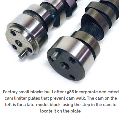
is the cam retainer plate locked in place?
spring bind height checked? (to exceed max valve lift by .050 min.)
oil return holes cleaned of casting flash?
were steam holes in heads necessary?
were the spark plug threads of a installed spark plug extending into the combustion chamber?
rocker slot to rocker stud clearances ?
retainer to valve guide clearances?
spring bind height checked for the correct spring pressure?
valve lash/preload ?
are the valve springs the correct tension,height?dia.
keeper the correct angle? style? size?
valve seats the correct angles?
valves back cut?
have you rotated the engine and carefully watched and measured the valve train clearances and geometry?
valves the correct length, stems the correct diam.
strait?
rockers the correct ratio?
were the valve to valve guide clearances checked?
were the heads milled?
did the head gasket overlap the bore?
what are your valve train clearances?
is the rocker arm geometry correct!
chambers CC,ed
port work..(some steps optional)
(1) open throat to 85%-90% of valve size
(2)cut a 4 angle seat with 45 degree angle .065-.075 wide where the valve seats and about .100 at 60 degrees below and a .030 wide 30 degree cut above and a 20 degree cut above that rolled and blended into the combustion chamber
(3)blend the spark plug boss slightly and lay back the combustion chamber walls near the valves
(4)narrow but dont shorten the valve guide
(5) open and straiten and blend the upper two port corner edges along the port roof
(6) gasket match to/with intake and raise the port roof slightly
(7) back cut valves at 30 degrees
(8) polish valve face and round outer edges slightly
(9)polish combustion chamber surface and blend edges slightly
(10) remove and smooth away all casting flash , keep the floor of the port slightly rough but the roof and walls smoothed but not polished.
(11) use a head gasket to see the max you can open the combustion chamber walls
(12) blend but don,t grind away the short side radias
block
is the oil pump pick-up mounted 3/8"-1/2" from the oil pan floor/
is the windage screen mounted about 1/8" from the rotateing assembly/
is the pick-up brazed to the pump body?
has the oil pump relief piston in the oil pump been checked for free ,easy movement? clearance? spring tension?
is the oil pump pick-up tube inserted too far into the oil pump body,(binding the gears)
has the block been clearanced for the rotating assembly?
has the block been aline honed?
is the crank strait?
are the damper install keyway and threads ok?
counter weights clearanced?
MAGNAFLUXED?
OIL PASSAGES CLEANED?
GALLERY PLUGS INSTALLED CORRECTLY?
has the cam to rod bolt clearance been checked?
piston to valve clearances checked?
piston to bore clearances?
TRUST BEARING CLEARANCE?
what were the piston ring to slot clearances?
RING GAPS?
were the rings all checked individually for end gap in the cylinders they were used/installed in?
were the rings checked to make sure the correct side faced up, and the correct ring was in each groove?
what were the back clearance on the rings?
were the oil ring expanders carefully fitted for correct drag?
were the oil ring scraper ring rails checked for end gap?
total cam lift and remaining clearanceS?
WAS THE CAM DEGREED IN?
main bearing clearances?
what is the main bearing run-out clearance
piston to head clearance? (QUENCH?)
head gasket to coolent holes checked?
magnets installed?
rod bolt to block clearances?
what tq reading is necessay to spin the crank with no rods attached?
are the rod bolts and main caps torqued correctly? (rod bolts checked with a bolt stretch gauge?)
did you check the block for a strait main cap alignment?
what size journals and what were the bearings edge to filet clearance??
are the journals checked for finish and run-out/tapper?
did you use moly lube to assemble?
correct bearing crush?
did you pre-lube before start-up?
did the distributor gear fit the cam gear precisely?
was the distributor oil flow mod done?
was the correct style distributor gear used?
did you check the piston to piston pin bores for fit and clearance?
did the piston pins to snap ring clearance seem overly tight?
if they are pressed pins were they correctly matched and checked for free movement in the pistons?
was the engine ballanced?
cam button installed?, and lock plate installed?
were the rods resized? checked for parrallel bores/were the rods strait?
piston valve clearance notchs correctly located on the pistons? edges smoothed?
were the rods checked for length?
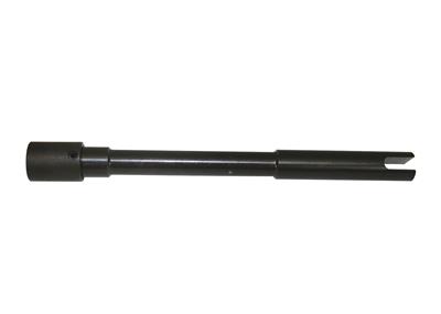
is there a few thousands clearance on the oil pump drive shaft AFTER the distributors bolted down?
did you install a steel collar on the oil pump drive shaft?
was the rod to piston pin side clearance checked? (at 4 places seperated bye 90 degree spots)
does the oil pump drive shaft mid section clear the block with the pump installed?
whats the starter to flywheel gear clearance?
is the pilot bearing to trans imput shaft clearance ok?
is the front motor mount bolt to fuel pump pushrod clearance ok? did the fuel pump pushrod move easily/
are you possitive the pistons were installed with the correct valve relief in the correct location?(eiieeiie) were the pistons installed with the correct side facing forward/
what torque values were used on all fasteners/ were they the correct length and type bolts?
were the bores honed with a torque plate in place?
was the cylinder finish correct for the type rings used?
was the oil pump itself checked for free spin and clearance AFTER THE PICK-UP WAS INSTALLED?
was the cam drive checked for free rotation and drag/
were the oil passage plugs drilled for extra oil flow?
Is the water pump you installed DESIGNED to rotate in the dirrection ITS going to be spinning with the BELTS installed like they are, remember there ARE waterpumps designed to rotate in either but not BOTH dirrections
were the lifter bores checked?
cam to timing cover clearance?
cam journal to cam bearing clearances?
was the cam journal run-out checked?
was the cam degreed in or just lined up useing factiory index marks?
has the rod and windage screen to oilpan clearnce been checked?
does the dipstick & tube clear the windage screen?
was the cam lobes/LSA/LIFT CHECKED?
is the deck square/level?
whats the cross hatch hone angle?
what grit hone was used? is it correct for the rings used?
are all the threads clean/clear?
brass freeze plugs installed?
block painted?
a few things to check
are the connecting rods installed with the beveled edge facing out on each pair with the bearing installed with the bevel facing out on both the lower and upper rod bearings also?
are you using beveled bearing shells that match the cranks throw bevels?
what are the bearing clearances? (are they the same checking at 90.120.160 degrees from the first measurement?}
what are the connecting rod side clearances?
is the crank strait? has it been turned undersize? if so...on ALL the rods? on ALL the mains? or on ALL the BEARINGS JOURNALS OR ONLY SOME?
whats the TRUST BEARING CLEARANCE?
is the piston side clearance correct?
are the pistons installed in the correct cylinders? (intake and exhaust notches correctly located to match the cylinder head)
are you POSSITIVE each main cap is in the correct location and FACING THE CORRECT DIRRECTION?
did you use MOLY assembly lube?
did you check EACH INDIVIDUAL RING ON EACH PISTON for ring gap clearance,AND that the rings fit the piston ring slots correctly? are any rings installed in the wrong ring slots (2nd ring in top slot ETC,)or upside down
do the rings have back clearance?
were the cylinders CORRECTLY HONED?
is the cam drive binding?
does the crank contact the windage screen?
does the dipstick tube or dip stick touch the crank at any point?
is the oil pump /cam gear binding?
did you check that the oil pump mounting bolt does NOT contact the back surface of the rear main BEARING under the main cap?
is the block warped, checked carefully?,was it line honed?
are the piston pins centered? do the pistons rotate thru an arc with little resistance?
are there any lock pins, spirolocs, tru-arcs contacting the cylinder walls?
are you sure the bearing shells are installed correctly and the locating tabs are in the correct slots?
are they the correct bearings for the application? or did you just assume the part guy knew what he was doing?
did you MEASURE or GUESS, did you at least use Plastigauge and a torqure wrench?
did you check EACH AND EVERY journal for tapper and roundness
did you get the rotateing assembly ballanced???
BTW
IVE dunked my piston/ring assembly's in a can of MARVEL MYSTERY OIL just before installation with a ring compressor and have never seen the slightest indication of problems either on ring sealing getting the rings broken in, or on tearing the engines down later for inspections
remember that when you go to re-install the compressed piston rings, and piston in the engine block,bores that dunking the piston in MARVEL MYSTERY OIL , just before, its slid into the ring compressor will coat the rings and bore contact areas enough to prevent many small problems that insufficient lube might case
let me give you some hard learned advice,that took awhile to sink in,something I was forced to learn years ago, MACHINE SHOPS AND MANUFACTURERS LIE AND MAKE MISTAKES.... DON,T assume they or ANYONE ELSE is telling the truth on clearance issues, or PARTS or MATERIALS USED, UNTILL YOU VERIFY they are correct YOURSELF after checking EACH and EVERY spring and valve, rocker and valve guide ETC
chances are good they are telling you the truth and youll probably be fine, [color]KNOW exactly WHAT your doing or ask for advice and measurements, NEVER ASSUME some part out of the box is correct and can be just bolted into place [/color]
but you sure won,t be the first guy to be told one thing and find something differant to be true after checking, take the time and effort to VERIFY clearances, spring rates and degree in the cam, and check clearances once its assembled.
one very good CD to get if your a beginer to engine assembly
http://www.themotorbookstore.com/resmchstvi.html
be sure you check clearances carefully, a mistake can and will damage the engine, DON,T GUESS,KNOW WHAT THE CLEARANCES ARE, ESPECIALLY SPRING BIND,VALVE TO PISTON,ROCKER TO ROCKER STUD, and retainer to valve guide clearances, CAM LOBE TO ROD, and anything or place thats suspected of being close I still use the strips of modeling clay about 1" square and .2" (two tenths thick) but one thing everyone forgot to mention so far is that you need to spray the piston and valve and clay strips with WD-40 to ensure the clay does not stick to any parts, otherwise the clay will tend to stick to the valve and piston allowing them to push the clay between them durring the compression of its surface by the valve (exactly what its there for) and PULL ON THE SURFACE of the clay as the valve moves away durring seperation (because the clay tends to stick ever so slightly as the parts pull away from each other if you don,t)which tends to give a false slightly greater than correct clearance measurement
most people tend to tell me Im wrong about that untill they try it both ways :grin: yeah the differance is usually minor but five to 10 thousands differance is not rare if the parts are clean and dry versus sprayed with an oil mist , first check to make sure that you are measureing correctly, many times the valve actual has more clearance in the flycut clearance notches,or only the very edge of the valves head and the edge of the notch are close and very minor cutting with a tool fitted in a valve guide will clear the problem and the valve has more clearance than measurements taken from the pistons upper surfaces, and that the head gasket thickness and valve train geometry are correct,
check if changing the cam retard/advance or installed possition can be changed to increase the clearance to 0.100 minimum on both the intake and exhaust valves (MOST LIKELY TO WORK WITH THE LEAST PROBLEMS)
add a thicker head gasket? ( BUT THAT TENDS TO RUIN QUENCH AND DOES NOT TEND TO BE A GREAT CHOICE ON MOST ENGINES)
look over the isky site they and MANY OTHER HOD ROD TOOL SUPPLY SHOPS SELL TOOLS THAT APPEAR TO BE EXTRA LONG STEM VALVES WITH CUTTERS ATTACHED TO FIX THAT PROBLEM
http://www.iskycams.com/pdfcatalog/PAGE17.pdf
heres a few things that should always be checked on an engine build
heads
are the pushrods perfectly strait?
do the pushrods flow oil?
rocker studs/guides torqued correctly?
do the head bolts have washers under the bolt heads? are they the correct length for the cylinder heads in use?
have the heads been pocket ported?
combustion chambers unshrouded?
combustion chambers pollished?
intake ports gasket matched"
are the valve guides cut to the correct length?
are the heads pocket ported?
is the retainer to valve guide clearance correct?
are the valve guide oil seals installed?
is there valve spring seats installed?
inner damper springs installed?
do the lifters spin easily in thier bores (FLAT TAPPET CAMS)
are the lifters prevented from getting out of cam lobe alignment over the full range of rotational clearance(roller cams)
do the lifter guides, or retainers hit the block? bind?(roller cams)
is the cam retainer plate locked in place?
spring bind height checked? (to exceed max valve lift by .050 min.)
oil return holes cleaned of casting flash?
were steam holes in heads necessary?
were the spark plug threads of a installed spark plug extending into the combustion chamber?
rocker slot to rocker stud clearances ?
retainer to valve guide clearances?
spring bind height checked for the correct spring pressure?
valve lash/preload ?
are the valve springs the correct tension,height?dia.
keeper the correct angle? style? size?
valve seats the correct angles?
valves back cut?
have you rotated the engine and carefully watched and measured the valve train clearances and geometry?
valves the correct length, stems the correct diam.
strait?
rockers the correct ratio?
were the valve to valve guide clearances checked?
were the heads milled?
did the head gasket overlap the bore?
what are your valve train clearances?
is the rocker arm geometry correct!
chambers CC,ed
port work..(some steps optional)
(1) open throat to 85%-90% of valve size
(2)cut a 4 angle seat with 45 degree angle .065-.075 wide where the valve seats and about .100 at 60 degrees below and a .030 wide 30 degree cut above and a 20 degree cut above that rolled and blended into the combustion chamber
(3)blend the spark plug boss slightly and lay back the combustion chamber walls near the valves
(4)narrow but dont shorten the valve guide
(5) open and straiten and blend the upper two port corner edges along the port roof
(6) gasket match to/with intake and raise the port roof slightly
(7) back cut valves at 30 degrees
(8) polish valve face and round outer edges slightly
(9)polish combustion chamber surface and blend edges slightly
(10) remove and smooth away all casting flash , keep the floor of the port slightly rough but the roof and walls smoothed but not polished.
(11) use a head gasket to see the max you can open the combustion chamber walls
(12) blend but don,t grind away the short side radias
block
is the oil pump pick-up mounted 3/8"-1/2" from the oil pan floor/
is the windage screen mounted about 1/8" from the rotateing assembly/
is the pick-up brazed to the pump body?
has the oil pump relief piston in the oil pump been checked for free ,easy movement? clearance? spring tension?
is the oil pump pick-up tube inserted too far into the oil pump body,(binding the gears)
has the block been clearanced for the rotating assembly?
has the block been aline honed?
is the crank strait?
are the damper install keyway and threads ok?
counter weights clearanced?
MAGNAFLUXED?
OIL PASSAGES CLEANED?
GALLERY PLUGS INSTALLED CORRECTLY?
has the cam to rod bolt clearance been checked?
piston to valve clearances checked?
piston to bore clearances?
TRUST BEARING CLEARANCE?
what were the piston ring to slot clearances?
RING GAPS?
were the rings all checked individually for end gap in the cylinders they were used/installed in?
were the rings checked to make sure the correct side faced up, and the correct ring was in each groove?
what were the back clearance on the rings?
were the oil ring expanders carefully fitted for correct drag?
were the oil ring scraper ring rails checked for end gap?
total cam lift and remaining clearanceS?
WAS THE CAM DEGREED IN?
main bearing clearances?
what is the main bearing run-out clearance
piston to head clearance? (QUENCH?)
head gasket to coolent holes checked?
magnets installed?
rod bolt to block clearances?
what tq reading is necessay to spin the crank with no rods attached?
are the rod bolts and main caps torqued correctly? (rod bolts checked with a bolt stretch gauge?)
did you check the block for a strait main cap alignment?
what size journals and what were the bearings edge to filet clearance??
are the journals checked for finish and run-out/tapper?
did you use moly lube to assemble?
correct bearing crush?
did you pre-lube before start-up?
did the distributor gear fit the cam gear precisely?
was the distributor oil flow mod done?
was the correct style distributor gear used?
did you check the piston to piston pin bores for fit and clearance?
did the piston pins to snap ring clearance seem overly tight?
if they are pressed pins were they correctly matched and checked for free movement in the pistons?
was the engine ballanced?
cam button installed?, and lock plate installed?
were the rods resized? checked for parrallel bores/were the rods strait?
piston valve clearance notchs correctly located on the pistons? edges smoothed?
were the rods checked for length?
is there a few thousands clearance on the oil pump drive shaft AFTER the distributors bolted down?
did you install a steel collar on the oil pump drive shaft?
was the rod to piston pin side clearance checked? (at 4 places seperated bye 90 degree spots)
does the oil pump drive shaft mid section clear the block with the pump installed?
whats the starter to flywheel gear clearance?
is the pilot bearing to trans imput shaft clearance ok?
is the front motor mount bolt to fuel pump pushrod clearance ok? did the fuel pump pushrod move easily/
are you possitive the pistons were installed with the correct valve relief in the correct location?(eiieeiie) were the pistons installed with the correct side facing forward/
what torque values were used on all fasteners/ were they the correct length and type bolts?
were the bores honed with a torque plate in place?
was the cylinder finish correct for the type rings used?
was the oil pump itself checked for free spin and clearance AFTER THE PICK-UP WAS INSTALLED?
was the cam drive checked for free rotation and drag/
were the oil passage plugs drilled for extra oil flow?
Is the water pump you installed DESIGNED to rotate in the dirrection ITS going to be spinning with the BELTS installed like they are, remember there ARE waterpumps designed to rotate in either but not BOTH dirrections
were the lifter bores checked?
cam to timing cover clearance?
cam journal to cam bearing clearances?
was the cam journal run-out checked?
was the cam degreed in or just lined up useing factiory index marks?
has the rod and windage screen to oilpan clearnce been checked?
does the dipstick & tube clear the windage screen?
was the cam lobes/LSA/LIFT CHECKED?
is the deck square/level?
whats the cross hatch hone angle?
what grit hone was used? is it correct for the rings used?
are all the threads clean/clear?
brass freeze plugs installed?
block painted?
a few things to check
are the connecting rods installed with the beveled edge facing out on each pair with the bearing installed with the bevel facing out on both the lower and upper rod bearings also?
are you using beveled bearing shells that match the cranks throw bevels?
what are the bearing clearances? (are they the same checking at 90.120.160 degrees from the first measurement?}
what are the connecting rod side clearances?
is the crank strait? has it been turned undersize? if so...on ALL the rods? on ALL the mains? or on ALL the BEARINGS JOURNALS OR ONLY SOME?
whats the TRUST BEARING CLEARANCE?
is the piston side clearance correct?
are the pistons installed in the correct cylinders? (intake and exhaust notches correctly located to match the cylinder head)
are you POSSITIVE each main cap is in the correct location and FACING THE CORRECT DIRRECTION?
did you use MOLY assembly lube?
did you check EACH INDIVIDUAL RING ON EACH PISTON for ring gap clearance,AND that the rings fit the piston ring slots correctly? are any rings installed in the wrong ring slots (2nd ring in top slot ETC,)or upside down
do the rings have back clearance?
were the cylinders CORRECTLY HONED?
is the cam drive binding?
does the crank contact the windage screen?
does the dipstick tube or dip stick touch the crank at any point?
is the oil pump /cam gear binding?
did you check that the oil pump mounting bolt does NOT contact the back surface of the rear main BEARING under the main cap?
is the block warped, checked carefully?,was it line honed?
are the piston pins centered? do the pistons rotate thru an arc with little resistance?
are there any lock pins, spirolocs, tru-arcs contacting the cylinder walls?
are you sure the bearing shells are installed correctly and the locating tabs are in the correct slots?
are they the correct bearings for the application? or did you just assume the part guy knew what he was doing?
did you MEASURE or GUESS, did you at least use Plastigauge and a torqure wrench?
did you check EACH AND EVERY journal for tapper and roundness
did you get the rotateing assembly ballanced???
BTW
IVE dunked my piston/ring assembly's in a can of MARVEL MYSTERY OIL just before installation with a ring compressor and have never seen the slightest indication of problems either on ring sealing getting the rings broken in, or on tearing the engines down later for inspections
remember that when you go to re-install the compressed piston rings, and piston in the engine block,bores that dunking the piston in MARVEL MYSTERY OIL , just before, its slid into the ring compressor will coat the rings and bore contact areas enough to prevent many small problems that insufficient lube might case
Last edited by a moderator: