Engine Lubrication, External Components, Check Valve

voodovette

Member
Hello All...

Long time(longer story), no speak... Sorry about that.

Anyway, as the result of a Comp Cams Pro-Magnum Steel Roller Rocker Arm failure(unfortunately the second one,
with never-so-much as a pop, snort or backfire), I am reconfiguring the external lubrication remote filter
(A/C Delco PF35L) and Oil Cooler lines to incorporate 1, maybe 2, MOROSO Pt. #23875, 1/2 NPT Oil System
Check Valve(s), after catching the failure within seconds and recovering/accounting for all bits.

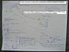
The rather rude schematic attached below was sketched out for a proposed High Point Fill location, but for
purposes of this conversation, I've annotated it with the suggested insert locations.

The remote Filter is located below the level of the bottom of the engine block, mounted to the inside of the
vehicle frame. The Remote Cooler is located up and forward in front of the drivers side Valve Cover, behind
the Rad.

The object is to prevent drain back as the PF35L does not have anti-drain back, so when not running
there will be an undetermined amount of drainage due to gravity.

Curious to see what feedback/experience there may be on this topic with particular regard to potential flow
restrictions utilizing 2 of these Check valves in the indicated positions.

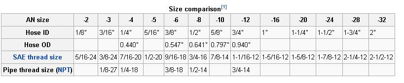
The balance of the remaining plumbing for all external components is AN-8.

Interesting to note that Canton sells what appears to be the exact same part for all Accu-sump applications
which rely on very quick fill rates, so I'm theorizing they do not represent any significant restriction, however
"Theory" and "Proof" are 2 different things.


just for the fun of it... here's a current pic. of the old beast...


For WWII Aviation History Buff's .... the bottom pic was taken outside
Canadian National Air Force Museum where a swarm of 80 and 90 year
old guys took 10 years to restore to airworthy a 1944 Avro Halifax
Heavy Bomber powered by 4 Rolls-Royce Merlin's.

The Halifax was rescued from 800 feet underwater in a lake in Norway
where it was shot down on it's first mission and then sat there, basically
in one piece, for about 50 some-odd years before re-discovery.


.
 

Attachments

  • 6.7.13.No.1.Schematic.Main.Lubrication.External.Components.c.jpg
    6.7.13.No.1.Schematic.Main.Lubrication.External.Components.c.jpg
    386.4 KB · Views: 102
  • 11.13.11.NationalAirForceMuseum.C4.jpg
    11.13.11.NationalAirForceMuseum.C4.jpg
    333.5 KB · Views: 102
first, nice looking corvette!
ok what I think your talking about is adding an oil accumulator as an extra source of high pressure oil in case of a potential failure of some engine component to hopefully reduce or eliminate engine damage between that part failure and when you can turn off the engine!

the first thing Id point out is theres zero reason to include the oil accumulator, in sequence in that oil cooler line, it would work just as well in a secondary access point to the oil systems passages

BBCoilcoolerports-2.jpg

BBCoilingCustom.jpg


anfitchartz.jpg

This is a cut and paste i stumbled on. I know alot of people ask about this so I thought I would put it over here.
Big Block Chevrolet Gen V and Gen VI Oiling SystemSolving the mystery of the Gen V and Gen VI Priority Main Oiling system
Priority Main Oiling System
The Generation V and VI big block Chevrolet blocks feature a priority main oiling system where the main oil supply passage is located adjacent to the camshaft tunnel. Drilled passages which intersect this large oil tunnel carry oil directly to the main bearings. If you are facing the front of the block with the engine in the upright position, this main oil supply tunnel is located in the 2 oÂ’clock position just below the right hand lifter oil supply line.
Oil Cooler Plumbing
Located along the oil pan rail just ahead of the oil filter pad are two drilled and tapped (3/8” NPT) oil passages for routing oil to an external oil cooler. The hole located closest to the oil filter pad (#2) is for the outgoing supply line to the oil cooler. The front passage (#1), which is farthest from the filter pad, is the return line from the oil cooler.
Careful examination reveals that these two passages intersect the same return line that feeds oil back to the main oil tunnel. This requires that a special fitting be used in the #2 supply line to prevent oil from short circuiting the oil cooler.
Part number SD1540 provides the necessary diverter basket to prevent the supply oil from entering the return line before going to the oil cooler. This fitting has a dash 10AN thread to allow the use of aftermarket components to plumb your external oil cooler. The front passage #1 will require a 3/8” NPT by dash 10AN adapter (#FCM2185), which is available from Scoggin-Dickey.
Understanding By-pass Valve Locations
Factory assembled 454, 502 engines and short blocks have two by-pass valves installed in the block. These factory installed by-pass valves (#25013759) will open at an 11 psi pressure differential. One by-pass valve is installed in the center hole on the oil filter pad (#4). This hole is the oil return passage from the oil filter. The second by-pass valve is installed in the adjacent hole (#3). The egg shaped hole (#5) is the high pressure oil supply passage from the oil pump.
For all racing application that will NOT use an oil cooler but will maintain the stock oil filter location, you must remove the center by-pass valve in location #4. Removing this valve eliminates three redundant right runs in the oil system. However, if you leave this by-pass in place the oil system will still function as it was intended, but a loss of oil pressure can result from the four right angle turns required for oil to return to the main oil tunnel.
If you intend to use a remote oil filter, a high pressure by-pass valve part number 25161284 must be installed in position #3. This valve will open at a 30 psi pressure differential. A plug will be installed in position #4 to prevent oil flow thru this passage. Oil should be returned to the block in the 3/8” hole located just able the oil filter pad. An oil filter block off plate kit (#SD3891) can be purchased from Scoggin-Dickey for Gen V and VI blocks to plumb your external oil filter.
If you intend to maintain the stock filter location and will use the factory provided oil cooler passages to install your oil cooler, then you must install two high pressure by-pass valves (#25161284). One will be installed in location #3 and the second in location #4.
read thru these links
viewtopic.php?f=54&t=1280&p=2741&hilit=accusump#p2741

viewtopic.php?f=54&t=120&p=28636&hilit=shrapnel#p28636

viewtopic.php?f=51&t=1458&p=22845&hilit=shrapnel#p22845

viewtopic.php?f=54&t=2187
 
Thanks for your reply Grumpy, and thanks for your
compliment on the car. C-4's don't get much love, but 285's on front
and 335's on rear with correct offsets, dished 18" wheels and lowered...
they can still look sweet.

The purpose of the post as indicated in the title, was actually to focus on:

1) the installation points for check valve(s) as indicated by the annotated
Green Ovals in the hand drawn schematic.

2) the validity of using two check valves to prevent drainage/back-flows from the
high points in the external circuit.

3) any concerns associated with flow restriction created by Check Valve(s)

The schematic was done previously for a proposed High Point Fill Port which
you could also call an accumulator tank, but for this application was simply to be
able to fill the extremities of the external Lubrication circuit after an oil change
to prevent/reduce any dry start-up time.

Do you have any experience with integrating Check Valves into remote filter/cooler circuits?

If so, has Flow restriction ever been a concern?


.
 
You should only use 10 AN 5/8" ID BRAIDED RACING HOSE TO PLUMB AN OIL COOLER & EXTERNAL OIL FILTERS.
REDUCE ALL CHANCES OF RESTRICTED ENGINE OIL FLOW.

DON'T LIKE THE IDEA OF CHECKVALVES.R SOMETHING TO MALFUCTION FAIL AT THE WORST TIME.

WHY DID THE COMP CAMS PRO MAGNUM STEEL BODY ROCKER ARMS FAIL ON YOU TWICE ?
WHAT RATIO ROCKERS USED ? 1.7, 1.8, 1.9'S ?
OR THE TYPICAL 1.5 & 1.6 ?

Brian
 
If you believe you have oil control issues Good top notch racing oil pan the best fix. $600+.
Or Dry Sump. Best solution but expensive. 11 quart oil holding tank.
4 scavange sections & 1 pressure side in gearmore belt driven oil pump.
 
If you run a Dual Filter External. Remote system...
The engine side Filter used should have an intetnal Flapper Valve.
The secondary outlet to oil cooler should have no flapper internal checkvalve.
Must use the Series Oil Flow Dual Element Remote setup.
Parallel oil flow also made.
Setup correct NO EXTERNAL CHECKVALVE REQUIRED.
 
Thanks 87v81b...

2 things....

1, on the rockers.... 2, on the check valve issue


1) The Pro Magnum Steel 1.7 BBC rocker arms were selected for their strength
and durability.

The engine was completed 4 years ago now and the first one failed
at about 15 hours of run time the first year. No. 3 Intake.

It broke across the bottom of one side of the trunion casting, a clean break,
but the continued motion of the engine running at the time cause it to deflect
in an angular way up the stud because it no longer had support for one side of the pivot.

At the time we wrote it off as a fluke, we were on the road, and a buddy with
a spare set of Crane Gold's dropped one in after we'd recovered all the bit's and
changed the oil.

Ran great ever since .... 3 full seasons and the borrowed Crane gold is still in there.

A few weeks ago, I fired it up and there was an audibly louder than normal valve train ticking
so I immediately pulled valve covers and found the same thing... No. 7 Exhaust.

A close friend who built and runs his own Top Fuel Rail Car and is the 30 year owner of the
largest regional industrial machine shop took one look at it and said...

"Die Cast and poor hardening"... a quick opinion subject to review, but from a qualified source.

I don't trust this batch any more, evidently there's a flaw. If you look up the Factory Five
Cobra Support Forums, you can see excellent macro pic.s of exactly the same failure...
so I'm not the only one.

The cam is a mild 238 @.050 with .560 lift,and the engines never seen
over 5000 R.P.M. so it's not due to high stress.

The oil is Shell Rotella T, 15W40 Conventional, with a dash of Comp's ZDDP Break-in, in
a fully baffled 10 litre pan.

I've got a spare set of Crane Gold's here at home, so until I can get it straightened
around with Comp's Warr., the Gold's are going in.

2) With a bit of experience in heavy marine diesel pre-lube systems with 100,000's
hours use, similar inline check valves, I've never seen them as a cause of terminal failure,
so while statistically possible, I'm less worried about that than the accumulative wear
of dry starts.

I certainly see the value of AN-10 as having more flow capability, as well as the dual
element, series rigged, filtration.

For a Road Race BBC working between 5500 to 7000 for an average operating range
I could see that would be critical, so I'm hoping that until budget permits, the sub-3000
range this thing see's for 95% of the time, the AN-8 can still support adequate flow.
Upgrading to AN-10 and dual element series filtration will require a complete redesign
due to space, time and budget needed, so that's a future winter project.

Anecdotally speaking, was at the Syracuse Nationals last year and I must say that
the vast majority of external lube systems in the Hot Rod zone seem to be plumbed with
AN-8.

Of course, that does not make them right, it just appears to be the way it is.


.
 
Use 10 AN fittings and zero 90 degree elbows if at all possible.
I have personally plumbed plenty of true 7-8 second ET race cars frim 2001-2008 till the economy crashed.
BBC NEEDS PLENTY OF OIL VOLUME AT ALL TIMES.
DO NOT CHANCE OR SHORTCUT.

SOMETHING REALLY WRONG WITH THE HOTROD USA PARTS SUPPLIERS. IT SEEMS THEY HAVE LET GO ALL THE LONGTIME ENGINEERS.
LIKE GRUMPY.
WANNA BE RETARDS LEFT .
IT SUCKS.
 
I have the Original series of Comp Engineering Pro Magnum Rocker Arms for my 410 ci Sbc.
They are NOS from 1996-1997.
Also purchased a Half set of Comp Engineering Pro Magnum Steel Rocker Arms the Current style in production.
For the intake side only.
After sharing your CC rocker arm stories I think I won't use them.
Going to Buy Crower 18PH Stainless steel Enduro Rocker Arms
Proven design & Race tested since 1968. Never seen them fail.
Have Crower Endur stainless 1.65 Rockers on my 70 TA 462ci.
8000+ Rpm & never broke.

Thanks.
Saved my 410 likely from valvetrain failure.

Brian
 
As can often take place, the topic can morph, in this case to the rocker story,
but I would not hesitate to use the newer designed Pro-Mag's, the Black ones.

If you look at the thickness of the bottom of the trunion supports, they seem twice
as thick as the orig. design that had a narrow elliptical ridge shape cast into the
otherwise thin bottom, 180 degrees below the trunion axle/bearings.

The new Black ones are the full thickness from shoulder to shoulder on both lower
trunion half's adjacent to the stud pivot. I've not yet had the opportunity to put a
digital calliper on them, but a quick visual suggests, as mentioned above,
the new ones are close to, if not twice as thick below the trunion axle.

As these orig. parts had a lifetime warranty, I fully hope and expect that Comp will
replace them with the newer, obviously more robust version which are also lifetime
warranty'd and I will install them and use them willingly.

It is not my intention to criticize Comp until they have had a chance to respond
after I submit a claim. I have the orig. purchase invoice for them somewhere in the
build file and I will send it all in and report back on that in due course.

I believe that for the price, Comp offers a superior value as a lot of the competition
is double, triple or more, the money for Steel Roller Rockers. Also, I have many other
Comp parts that are working flawlessly.

Even a new Rolls-Royce has a warranty, just in case, so we have to accept that things
can happen.


.
 
I will think about.
New Rockers are Black Yes. Shotpeened surface. Believe they were parkasized from Comp.
Still have lots of faith in Crower Enduros.
Don't need shaft rockers in my application.
Though they are best.
All aluminum rocker arms have a usefull fatique lifespan.
Engine opetating heat degrades the aluminum metal grain structure.
Stainless 18PH Steel has best fatigue life. Only surpassed by Vandium chrome moly steel or Titanium.
All Crane Gold Rocker arms are Extruded Billet aluminum. Best aluminum rocker arms you could buy since 1970.
Not cast as you were told.


Brian
 
Just to clarify/review...

The reference to "Cast" in the previous post...

I was told the Comp Gen. 1 Pro-Mag's were die cast... not the Cranes, we were examining the broken
Comp Trunion/axle lower housing/support.

We used a Crane to replace the broken Comp casting when far from home on a road trip so we could
continue to travel.

I also have a spare set of Crane's here at home, so they'll be going in temporarily.
 
I once read even the best vacuum degassed extruded billet aluminum bar stock manufactured roller rocker arms are good for 500 miles racing. After that they should be replaced or immenate failure will occur.
On the street of course you can not run s constant 7-9k. Rpms .
Different load fatigue life taking place.
Valvespring pressured used such as 400 pounds on the seat & 850-1000 pounds open at .750 lift will torture any rocker arm.

Be nice to own a decked out. Spintron machine with a 40 Hp electric motor to drive dummy test engine. Test all rocker arms. See what works best & how long in hours WOT . Calculate in street miles driven. Or on a racetrack.
 
Back
Top