Fabbing Custom Parts

2Loose

reliable source of info
Over a lot of years I've fabricated all kinds of parts for all kinds of machinery,
but farm equipment and cars, trucks and harleys is where most of my time went.
Thought I'd post some of my fabrication projects here from time to time, showing
as much of the process as I can and explaining why I'm doing it that way.

I'm an equipment engineer, college was UCD, which was pretty much just an ag
school when I was there, '59 - '63. Been working on farm equipment and farm
irrigation systems ever since. Hot rods started around 1956 with a wrecked '54
Chevy ragtop that I did a whole lot of work on until '67, when I moved to Maui.
Equipment Engineer for a 37,000 acre sugar cane plantation, wow, way cool....

I'll be back soon with some part I'm making or whatevers.

Please feel free to comment anytime on my posts as we go along.

AND, please feel free to post your own pix on parts you fabbed, along with the how and why as you worked on the project.

Aloha from Maui,
Willy
 
Last edited:
Thanks 2Loose for taking the time to share. I'm sure it will be good reading !!!
 
yes I think this could rather easily become a rather popular thread or maybe a forum if it proves to be as popular as it should be
 
I'll start with this, a small one, but had to put some thought into it....
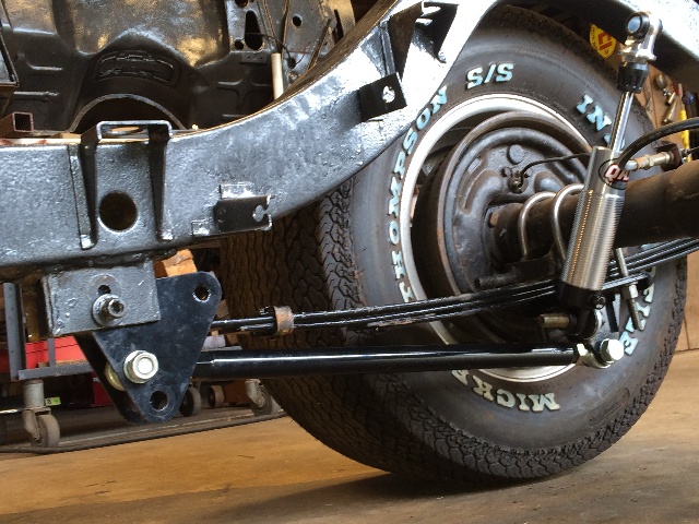
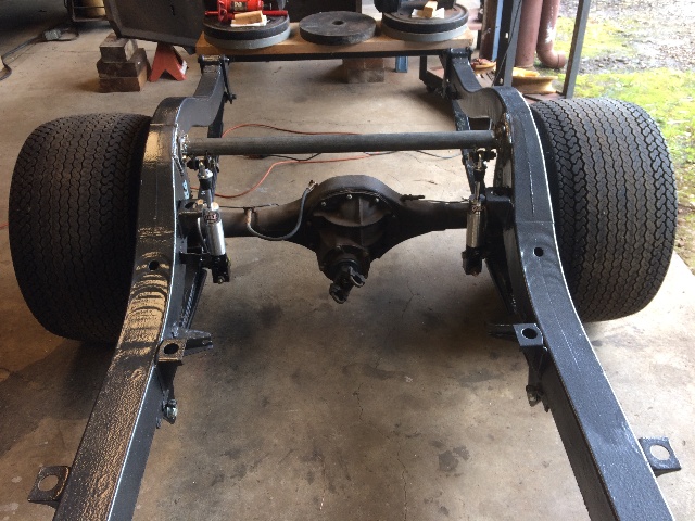
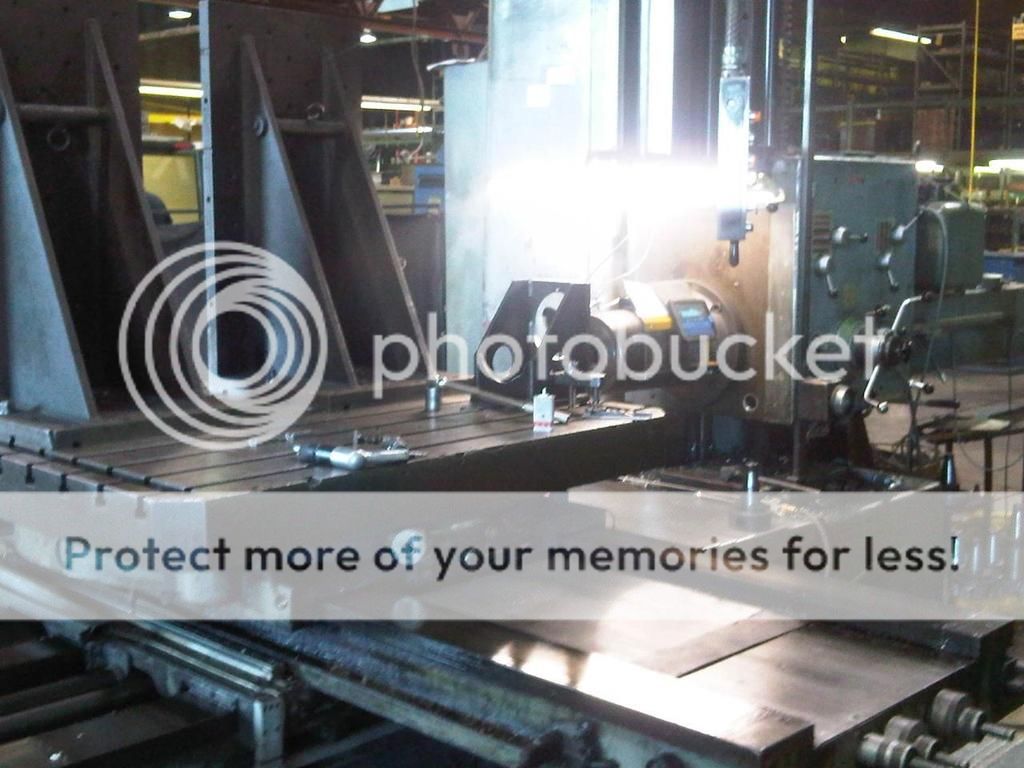
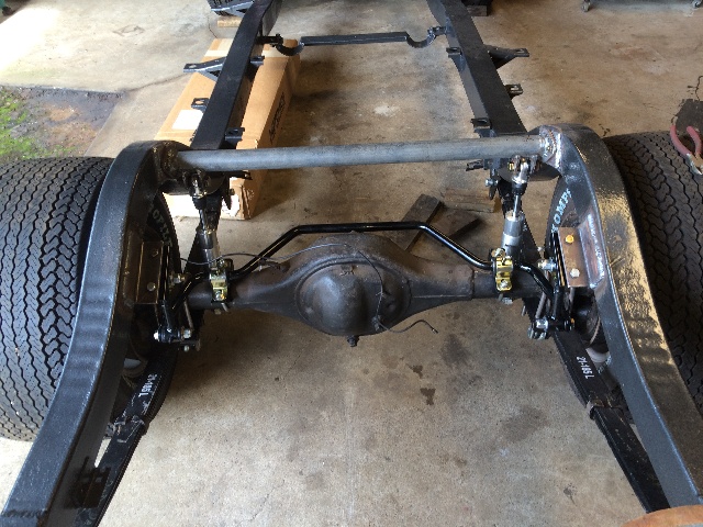
While setting up the rear suspension on my '55 Chevy Sport Coupe (hardtop),
a narrowed Ford 9", mini tubbed body, springs relocated under the frame rails,
no pocket kit in the rails, CalTraks installed, I wanted to try a dual spring setup
by removing 2 of the 5 leaves on each side, and putting QA-1's on, which gives me
adjustability on the shock settings, and I will run light coils on the shocks so I can have
some adjustability to the ride height and ride firmness. I have both 100 lb/in and
150 lb/in coils I can run, and expect to start with the 100's and see where it goes.
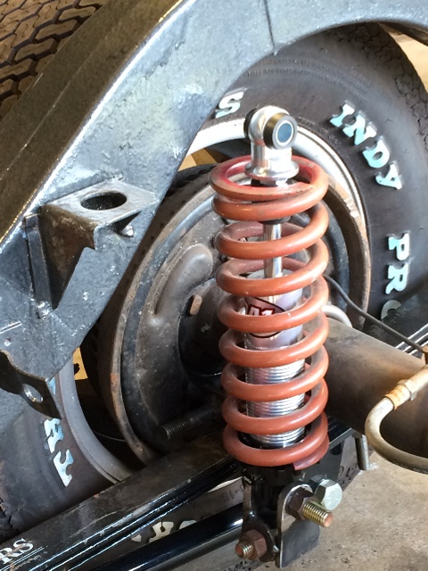
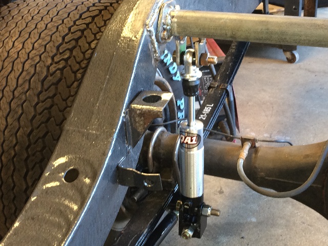
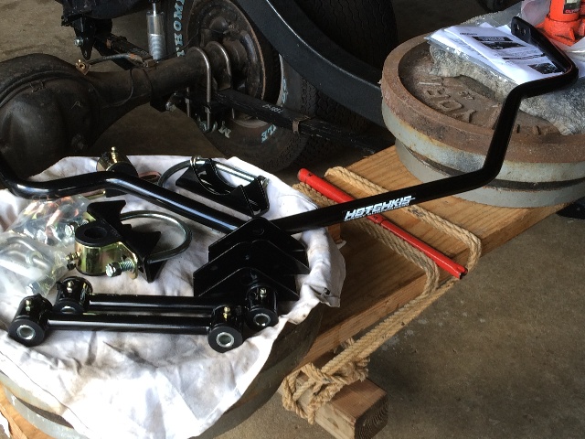
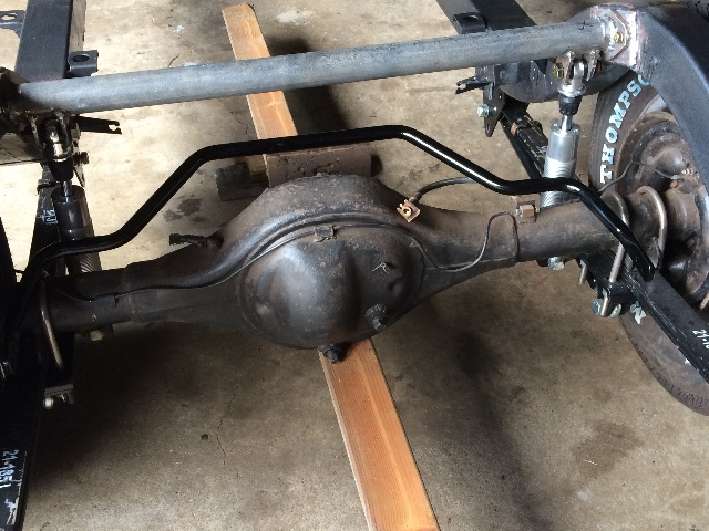
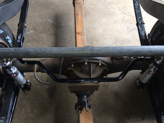
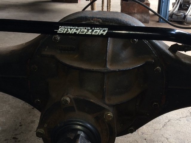
Also added a sway bar to that rear end. Running 10" wide 15" rims with Mickey
Thompson N50-15 Indy Profile tires that pretty much fill up the wheel wells
on this car.

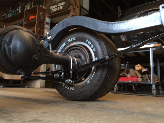
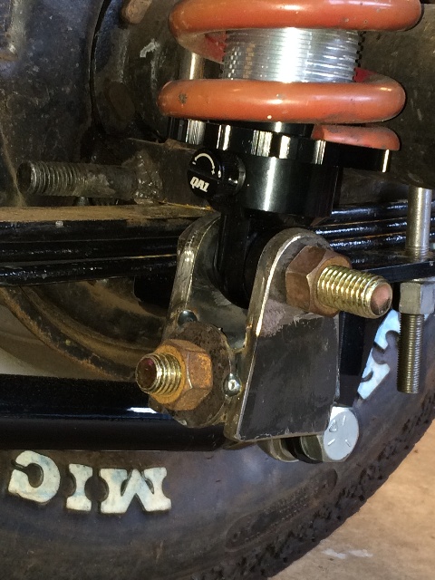
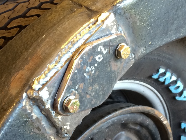
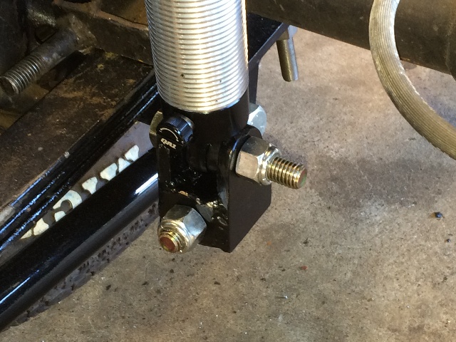
Originally had a 5/8" bolt on the bottom plate clamping the spring pack together
under the axle, it was facing forward giving a side to side rotation for the bottom
shock mount, found a piece of 2" pipe in good condition in my scrap pipe to use
as a shock bar up top.
58HTframe017s_May2015.JPG


58HTframe018s_May2015.JPG


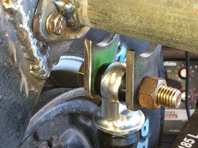
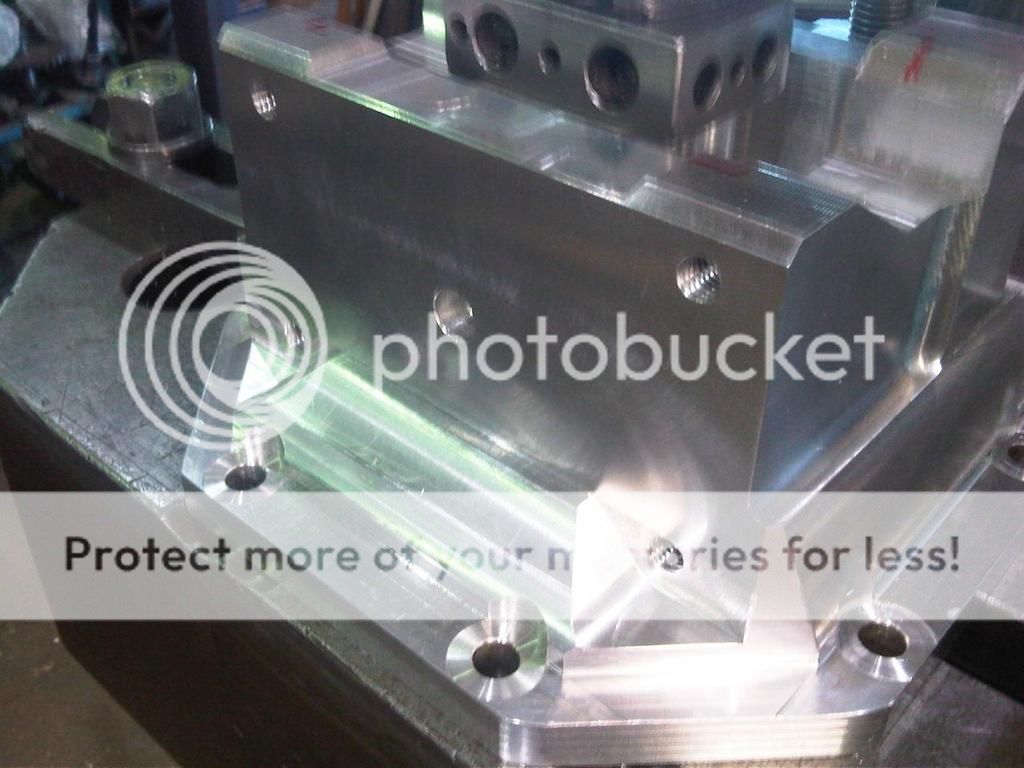
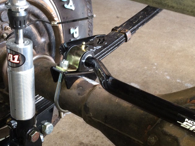
I want to mount the QA's vertically to get the maximum travel available (3.8"), QA recommends that I set ride height to give 60% compression available, so for these 14"
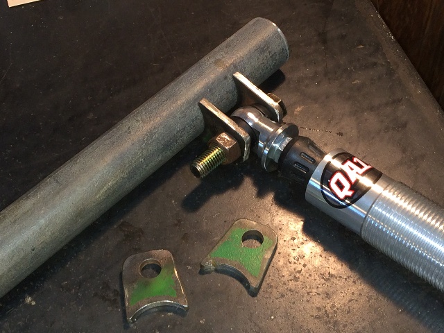
"Ultra-Ride" models that's 12.5" length bolt eye to blot eye. We have a lot of old gymn equipment in the shop, so piled a bunch of weights on the rear of the frame until I had the ride height I wanted at the rear axle. Holding the shocks in place, set at 12.5", I needed to raise them up about 3" at the bottom mount, that puts the top mount at about the right place to mount a shock bar. And I decided to turn the mounts around such that the rotation at the shock mounts would be front to rear, to be able to handle rotation of the rear axle, instead of side to side movement, as I think that will be pretty much constrained by the sway bar and the new poly bushings in the leaf spring ends.

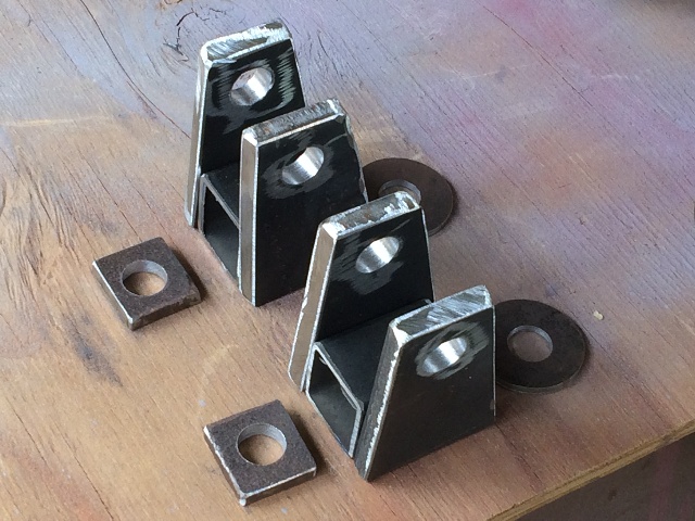
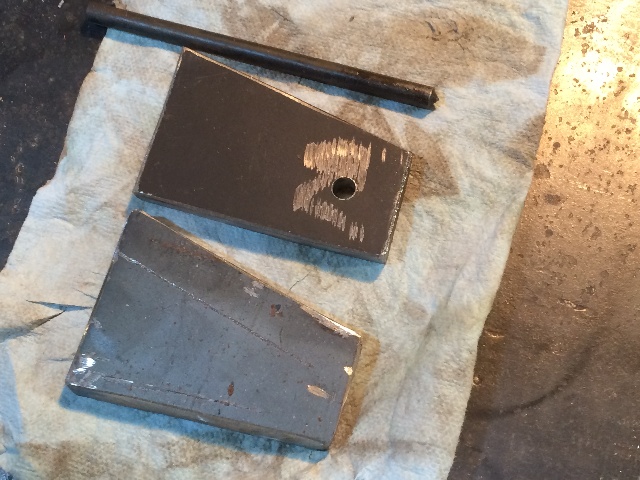
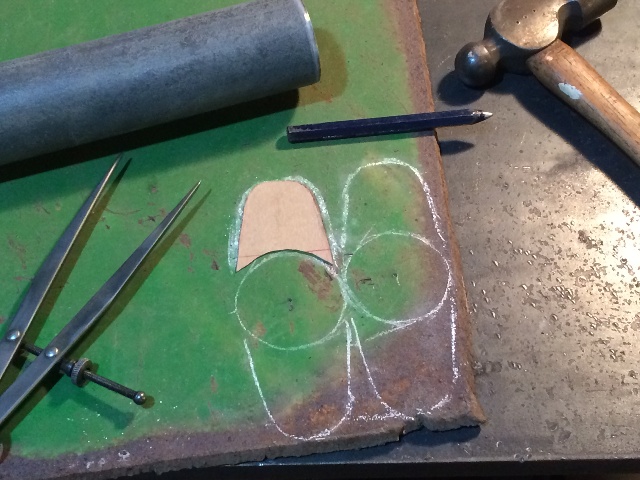
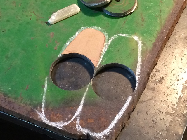
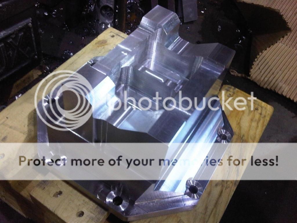
I did cut some cardboard templates for these side pieces, held them up to the bolt and the bottom of the shock until I got one I liked, then started cutting up steel, it's all stuff from my scrap pile I've accumulated over the years, and here's what I have for the bottom piece before welding:

58HTframe024s_May2015.JPG


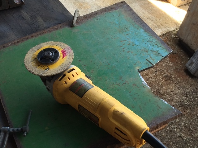
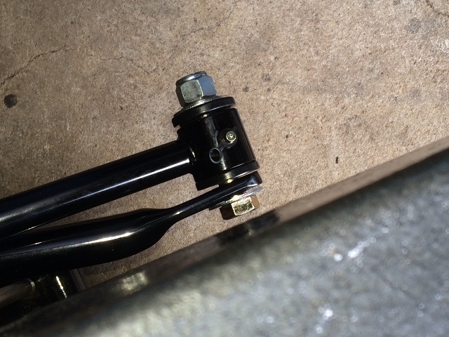
The mounts on the QA's are 1-1//4" wide, I had some square tubing that size, and had some 1/4" steel plate, and some 5/8" washers, so cut the side plates from the 1/4" with a 4-1/2" steel cutting disk. I like to use these disks to cut out these pieces, but I have to be careful, these disks can get caught in the steel and break, so as always safety glasses and gloves are mandatory when I cut steel this way.

58HTframe040s_May2015.JPG


I don't recommend running this cutoff blade without a guard, but I do use it this way from time to time, and have the scars to prove it!!!

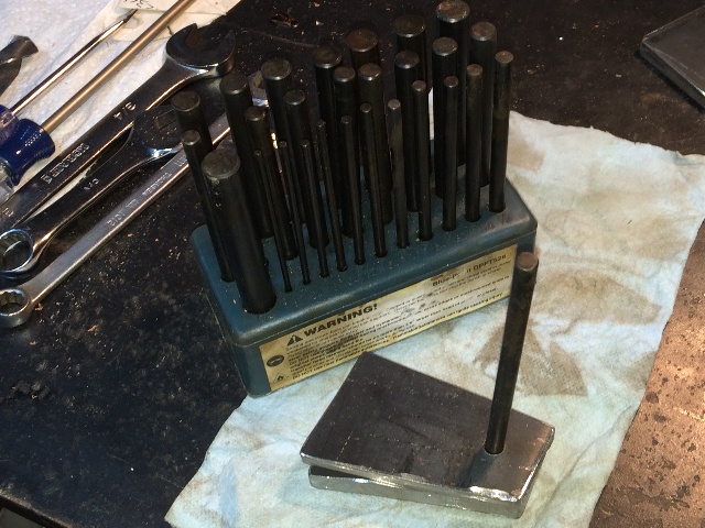
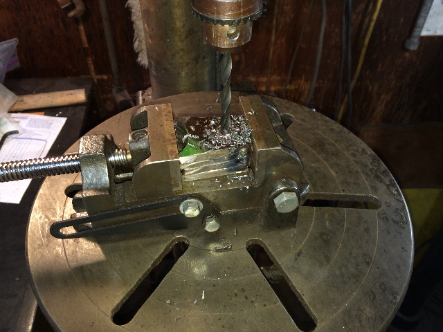
After using my cardboard template, and cutting out the four side plates first, I needed to drill 5/8" holes in them. Using my cardboard template I centerpunched the first piece, and drilled a 1/4" pilot in it.

58HTframe020s_May2015.JPG


I bought a set of transfer punches years ago, and it has been one of my more useful tools. Using the 1/4" punch, I transferred the center of that hole to the other three pieces and drilled pilot holes in all of them.

58HTframe021s_May2015.JPG


58HTframe022s_May2015.JPG


Then the 5/8" drill. I have an old floor drill press I've had for about 40 years, it still works well for me....
And I've collected several drilling vices of different sizes, they work well to clamp pieces in a larger fixture, giving me good control of the pieces when drilling them. The vices can be c-clamped to the drill press table for even more control if needed, for these holes I was able to easily hold them in position while drilling them....

58HTframe023s_May2015.JPG


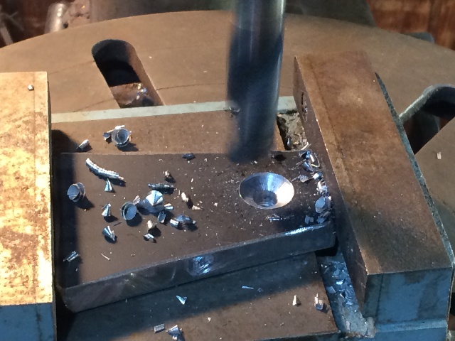
On these pieces I only drilled half way, then flipped them over in the vice and drill the rest of the way from the other side. It seems to give me a cleaner hole when I do that, but it could just be my imagination....

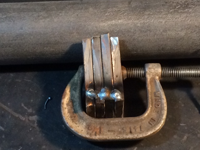
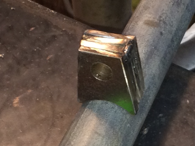
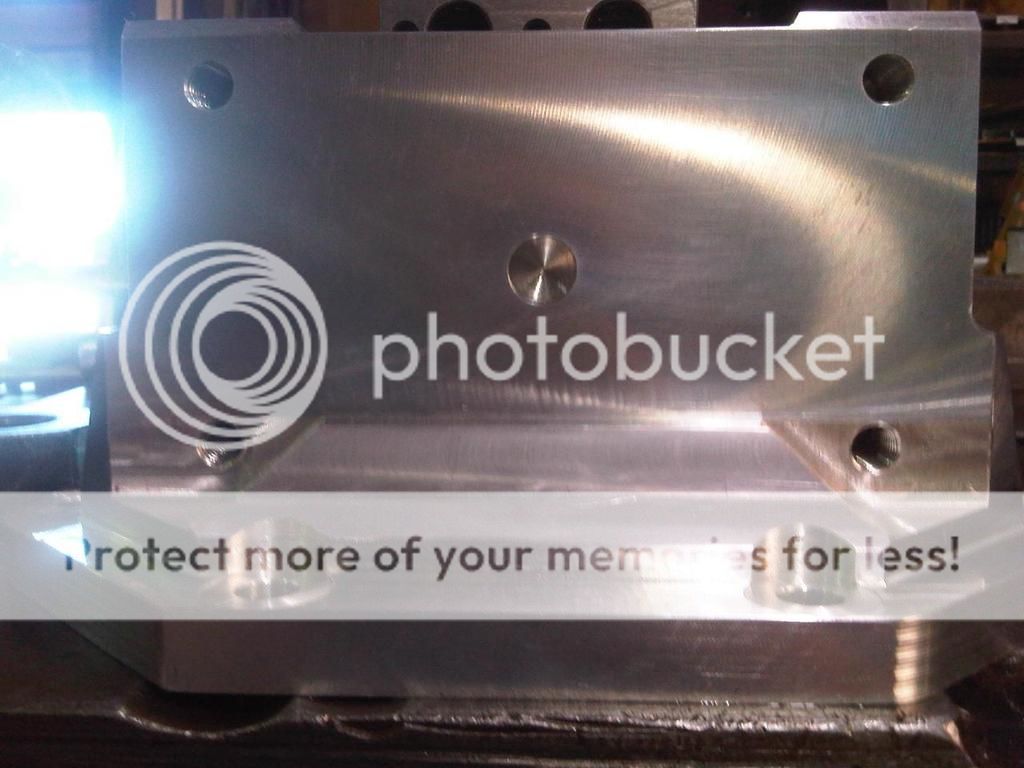
Tack welded the pieces together on one, dug out some old 250 lb/in springs I had laying around, and stuck them on a shock just to check for clearances around the spring...

58HTframe031s_May2015.JPG


I will use nylock nuts for the final assembly, these nuts are just a whole lot easier to use when doing setup work like this.....
And I have a set of old bins full of discarded old nuts and bolts to pull from, but generally buy new grade 8 stuff for work like this....

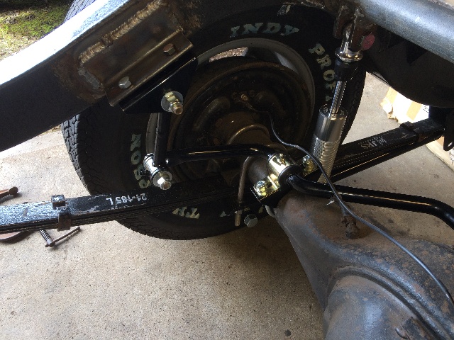
Lots of room for the spring next to the axle, I'll toss a bunch of 50 # weights on the rear of the frame until I get it down to ride height, then fab a removable shock bar to fit at 12.5" shock height.

58HTframe026s_May2015.JPG


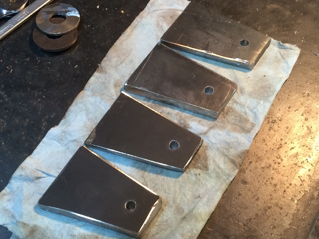
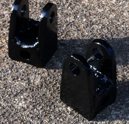
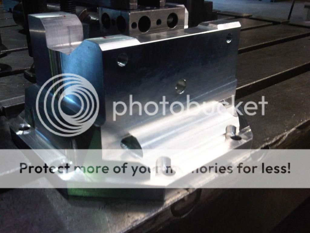
Finished welding and painted them. Used a mig I've had for many years.

55HTshockmounts_s.JPG


SHOCK BAR:

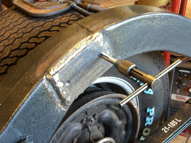
Am missing some of the pix I needed to show how I built the shock bar. First I measured the frame inside width just over the shocks, subtracted an inch, as there will be two 1/4" plates on each end of the 2" pipe, and cut it. Made a paper template of what I wanted the end plates on the pipe to look like, and from that came up with a size for the reinforcing plates I wanted to weld on the sides of the frame, and started cutting steel....

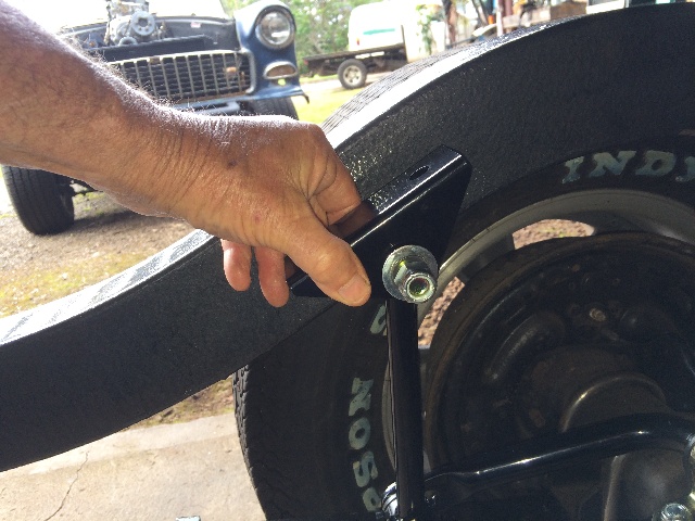
I wanted to bolt the shock bar in place on each side with 3/8" grade 8 bolts, so the end plates for the pipe were drilled for those two bolts each, then the hole locations were transfer punched to the reinforcing plates, and drilled with the correct size for tapping with a 3/8" NC tap. Then the reinforcing plates were located on each side and welded in place. The was a weld seam in the frame at one corner of the reinforcing plates that helped locate them fairly precisely on each side.

58HTframe041s_May2015.JPG


After welding the reinforcing plates on the frame, I ran the pre-tapping drill bit through the frame wall as well, then cut the threads all the way through.

Bolted the shock bar end plates in place....

58HTframe042s_May2015.JPG


I have a snug fit with the 2" pipe between these plates, so I can tap it in place and figure out what I want to do with it next....

Decided I wanted to fab the upper shock mount "ears" first and weld them on, then weld the shock bar itself in place to these mounting plates above....

Made a template and marked it out on 1/4" steel plate....

58HTframe032s_May2015.JPG


Used a 2" hole saw first to get the arc I needed to match that pipe....

58HTframe033s_May2015.JPG


58HTframe035s_May2015.JPG


Cut 'em out with the 4-1/2", shaped them a bit on the bench grinder...
Then lined them up on the pipe and tack welded them together...

58HTframe036s_May2015.JPG


This time instead of transfer punches, I'm going to drill all four at once....

58HTframe037s_May2015.JPG


A smaller hole first, then the 5/8" hole....

Lookin' Good....

58HTframe038s_May2015.JPG


Smoothed them off a bit on the bench grinder, then fitted them to the pipe....

58HTframe039s_May2015.JPG


I'll keep adding to this as I can (time).....
 
Last edited:
Welded the shock bar in place, and set up the shocks with the mounts to mark where they should be welded....

58HTframe043s_May2015.JPG


I should have taken more time with these welds, I can do better than this !!!

58HTframe045s_May2015.JPG


With everything welded in place, removed the assembly nuts and put on the Nylock nuts. Always use Nylocks on suspension parts, never have had one come loose....

58HTframe044s_May2015.JPG


I think this will work just fine....

58HTframe047s_May2015.JPG


This is not ride height, the shocks are full extended here, with the 14" long shocks, eye to eye, it will be adjusted (with the coil-overs) to 12.5" long for the correct ride height, with 60% compression available out of 3.8" total shock movement available.

I had to do some fabrication while mounting the new sway bar, will show that next, but need to run right now, be back later....

More Later....
Willy
 
Last edited:
I have been working on this project with Mopar Bob Willy.
A one off Billet 6061 T6 Aluminum Diff cover for a C3 Corvette.
 
Beautiful work, and a really nice piece of machinery to have access to....
 
very cool thread willy, whenever i have time i snoop around your web page for good ideas and solutions to problems, i like that you take lots of clear pics it makes the whole thing alot easier to understand! thanks!
 
Here's a quicky, I wanted a sway bar on the rear of the '55 Chevy Sport Coupe.
Bought a nice setup from Hotchkis and set about installing it.
Problem: With the narrowed 9" rear end, the leaf springs relocated under the frame rails, the position the shocks now occupy, the sway bar does not fit under the axle, with the links to the frame fastened to the underside of the frame in front of the axle, as Hotchkis intended.

But by trying every conceivable way it could possibly work, I found a solution....

The Hotchkis parts, for a complete install:

55HTframe056s_May2015.JPG


This looks like the best position for the sway bar install:

55HTframe059s_May2015.JPG


I'll have to be very careful that during the full travel of the rear suspension, the front part of this sway bar will never come in contact with the 3rd member of my rear end....

55HTframe058s_May2015.JPG


With the bar upside down, the ends of the bar tilt up a little, making it easier to set adequate clearance with the 3rd member, and giving a better setup for the end links to the frame....

55HTframe062s_May2015.JPG


I had to tilt the sway bar axle mounts toward the rear slightly to make sure there was clearance for the coil-overs when I install them....

55HTframe063s_May2015.JPG


Normally Hotchkis wants these links mounted on the outside of the bar ends, and attached to the frame on the underside. Having the leaf springs under the frame rails prevents that. I got lucky though, by mounting the links on the inside of the ends, with the nylock nuts on the inside and the bolt heads on the outside, I have clearance with the frame rails and the leaf springs. It's a bit tight, but we shall see if there is any sideways drift of the sway bar in it's mounts, and if there is, I can always add some kind of "stopper" on the sway bar or the axle itself to keep the sway bar centered, if there is any tendency to drift to one side or the other....

55HTframe064s_May2015.JPG


The links were too long for this position at 8", so I shortened them to 5-1/2" by cutting 2-1/2" out of the middle and welding them back together, some paint and you can hardly tell....

55HTframe065s_May2015.JPG


Found some nice pieces of angle iron in my scrap pile, just right for me to weld onto the sides of the frame for brackets, it's stout 1/4" material, should work just fine to mount these end links....
Drilled and bolted in the end pieces Hotchkis provided with 3/8" grade 8 bolts and nylock nuts....

55HTframe072s_May2015.JPG


55HTframe071s_May2015.JPG


Bounced up and down on the rear of the frame with a couple of my buddies, and a couple of beers, it looks good to go !!! Couldn't get the frame to tilt sideways no matter what we tried....

The shocks in this pic are fully extended, 14" ctc on the mounts at each end. Once the body is on I can find out which spring, the 100 #/inch or the 150's, will work best as adjustable coil-overs on this rig, and with whichever spring is in there, set the proper ride height by adjusting the springs so the shocks are at 12-1/2" ctc, which is the ride height I want, and allows the suggested 60% compression stroke available for these shocks....

I tried this same setup on the front end of a '55 Chevy gasser that had a '48 ford front truck axle under it, with fewer leaf springs, using the QA-1's to fine tune the final front ride height and firmness, and it worked great, so am trying that same setup here on the rear of this car.

Now to take it all apart for some more cleaning and some fresh paint !
 
Last edited:
so far it looks really well though out and well fabricated, congrats!
 
Back
Top