factors you need to think about in your engine combo

grumpyvette

Administrator
Staff member
displacement

http://www.archive.org/details/3dAnimat ... InjectedV8

viewtopic.php?f=53&t=204

viewtopic.php?f=53&t=247

viewtopic.php?f=53&t=343

viewtopic.php?f=69&t=5357&p=16030#p16030

viewtopic.php?f=53&t=852

viewtopic.php?f=53&t=141

viewtopic.php?f=53&t=253

viewtopic.php?f=44&t=427

Duration_v_RPM-Range_wIntakeManifold01.jpg


dynamic compression ratio

viewtopic.php?f=52&t=1070

viewtopic.php?f=52&t=727

viewtopic.php?f=52&t=480

viewtopic.php?f=52&t=322

viewtopic.php?f=44&t=184

cam timing

viewtopic.php?f=52&t=324

viewtopic.php?f=52&t=1070

viewtopic.php?f=52&t=727

viewtopic.php?f=52&t=480

viewtopic.php?f=52&t=322


lubrication

viewtopic.php?f=54&t=64&p=77#p77

viewtopic.php?f=54&t=52

viewtopic.php?f=54&t=2376

viewtopic.php?f=54&t=65

viewtopic.php?f=54&t=615

viewtopic.php?f=54&t=2187


intake or induction design

viewtopic.php?f=44&t=859

viewtopic.php?f=44&t=745

viewtopic.php?f=44&t=384

port cross section and port stall speed


viewtopic.php?f=52&t=322

viewtopic.php?f=52&t=796

viewtopic.php?f=52&t=401

viewtopic.php?f=52&t=333

viewtopic.php?f=52&t=462

viewtopic.php?f=52&t=92

viewtopic.php?f=52&t=389
header and exhaust design


viewtopic.php?f=56&t=1166

viewtopic.php?f=56&t=3155

viewtopic.php?f=56&t=495

viewtopic.php?f=56&t=1503

viewtopic.php?f=56&t=185

viewtopic.php?f=56&t=2537


rear gearing and transmission used


viewtopic.php?f=71&t=741

viewtopic.php?f=71&t=584

viewtopic.php?f=71&t=386

viewtopic.php?f=71&t=555

viewtopic.php?f=71&t=1715

viewtopic.php?f=71&t=447

viewtopic.php?f=71&t=662

viewtopic.php?f=71&t=386&p=473#p473


helpful calculators

viewtopic.php?f=50&t=40&p=48#p48
 
Performance Small Block: Chevy Engines


By Dave Emanuel


Small block Chevy engines long ago became mainstays in both the traditional and high performance marketplace. So many of them have been rebuilt over the years, and so much has been written about the rebuilding process, it would appear that nothing more need be said.
But the small block engine has changed over the years and so have consumer preferences and orientation. Consequently, many long standing rebuilding techniques are due for a change, or at least some refinement. That is, assuming a "high performance rebuild" is more than a standard short block with high performance heads and a high lift cam.
Points to keep in mind are that many customers for high performance engines are much more informed than their counterparts of 10 or 20 years ago. As opposed to a still wet-behind-the-ears teenager, the current high performance customer will likely be 30 to 50 years old with some racing background and basic knowledge of proper machining practices.
It's also probable that he or she has been down the road before, may have had a bad experience with a previous shop and is a bit gun shy. The flood of questions gushing forth from the mouths of many high performance customers today is often a consequence of previous experience; they're looking for some verbal reassurance before spending money.
Being the most popular engine in the world, the small block Chevy presents a number of high performance opportunities. Originally introduced with a displacement of 265 cubic inches, the small block Chevy has grown over the years, ultimately reaching 400 cubic inches. Two economy versions, one displacing 262 cubic inches, the other a "whopping" 267 cubic inches were also produced, but these are entirely unsuitable for performance use.

Small Block Specifications
CID Bore Stroke
265 3.750 3.00
283 3.875 3.00
302 4.001 3.00
305 3.736 3.48
307 3.875 3.25
327 4.001 3.25
350 4.001 3.48
400 4.125 3.75

Since the 1950s, all bore/stroke combinations have been rebuilt in high performance form. However, at this late date, blocks with 4.00" bores constitute the lion's share of the performance business. There's also a sizable demand for 4-1/8" bore blocks from which 400+ CID small blocks are built.

Cylinder block

As with any rebuild, one that will produce a high performance engine starts with the block. In the overall scheme of things, only two types of cylinder blocks exist - those with two-bolt main caps and those with four. But over the years, dip stick position has changed, rear main seal configuration has been updated, and a variety of alloys have been used.
Dip stick position isn't much of an issue, unless you've ordered the wrong oil pan. Then you wind up with the dipstick on one side, the notch in the oil pan on the other, and an engine with a severe oil leak. Alloy content is a somewhat different matter. Thousands of high performance small blocks based on a standard alloy block casting have run successfully for years. But for maximum strength and longevity, a "high tin" block is preferable.
A block's alloy content is denoted by two figures cast into the front face, just above the main bearing bore, in the area normally concealed by the timing cover. Many production small blocks have the numbers "010," "020" or both cast into their front face, just above the main bearing bore. If both numbers are present, one above the other, it indicates that the block alloy contains 10% tin and 20% nickel. A single number, either a "010" or "020" represents the amount of nickel and indicates negligible amounts of tin.
No numbers, other than the casting numbers that are typically found beneath the timing cover, translates to only minor amounts of tin and nickel being present in the block alloy. (Tin and nickel are two metals that are commonly alloyed with cast iron to improve durability, hardness and heat dissipation.)
Although a "010"/"020" block is most desirable, it's not always possible to find one that's suitable for high performance use. Alloy composition aside, cylinder wall thickness is the overriding consideration in block selection, and one with no tin or nickel and thick cylinder walls is generally preferable to a high-nickel block with thin walls. Truck and older Chevy II blocks are reputed to have thicker than average cylinder walls, but there are no guarantees; sonic testing is the only way to be certain that wall thickness is adequate.
Beginning with the 1986 model year, Chevrolet began producing blocks with a one-piece rear main seal. There's enough difference between 1985 and earlier and 1986 and later blocks that oil pans and crankshafts are not interchangeable unless an adapter is fitted to the block. Most commonly, a crankshaft and oil pan designed for the older-style, two-piece seal is installed in a late model block with one-piece seal. Adapters allowing this to occur are available from a variety of aftermarket companies and through GM Performance Parts as p/n 10051118.
The introduction of hydraulic roller lifters for the 1987 model year brought about other cylinder block changes. To accommodate original equipment hydraulic rollers - which are of a different design than aftermarket types - the tops of the lifter bores were raised and machined flat. The tapped bosses were also added in the lifter valley so the sheet metal "spider" that holds the lifter link bars in place could be attached.
Standard hydraulic or mechanical lifters can be installed in a "hydraulic roller" block, but original equipment roller lifters cannot be installed in a "non-hydraulic roller" block. "Hydraulic roller" blocks also have a tapped hole on either side of the camshaft hole for attaching the retaining plate that's installed to prevent the camshaft from "walking" forward.
Another variation that can ruin an otherwise well-planned engine building party is main bearing diameter. Beginning with the 1968 model year, main journal diameter was increased from 2.30" to 2.45". On the other hand, all 4-1/8"-bore production blocks are machined for a 2.65" main journal diameter. Consequently, it's advisable to verify main journal, bearing and bearing saddle diameters to assure proper fit.
It's also advisable to disregard model year when determining block characteristics. Considering that new cars are typically introduced in September or October of the previous calendar year, it's not at all unusual for a casting date to disagree with the model year of the vehicle in which it was originally installed. Prior engine swaps can also confuse the issue, so accurate measurements should always be made.
For the 1992 model year, Chevrolet introduced a Second Generation small block known as the LT1. (Installed in 1992 and later Corvettes and 1993 and later Camaros, Firebirds and 1994-'96 GM "B" and "D" bodied full-sized cars). Within the Second Generation family, most major components are interchangeable. However, a 265 CID version of the engine was also produced, (the base Caprice engine) so don't be surprised if you come across an LT1 block with 3-3/4" cylinder dimensions. With the LT1's reverse flow cooling system, neither the block nor heads are interchangeable with a First Generation small block.
Irrespective of the block selected, a performance rebuild should include align honing. Many machinists either overlook or disregard the importance of align honing. But every critical block dimension is taken off main bearing saddle alignment, so align boring and/or honing should be the first machining operation and it must be done accurately.
When a block is align honed, you absolutely must have the oil pump installed and the bearing caps tightened to the required torque, using the same type of fasteners (either studs or bolts) that will be installed when the engine is assembled. This is critical because when you tighten the main cap bolts or studs, or the oil pump bolt, it distorts the cap.
It is obviously possible to build a high performance engine and forego align honing. But if the engine is "hammered" very often, or if the owner installs a nitrous oxide system, you may very well end up with an unhappy customer.

Crankshaft

Of course, the best choice for a high performance engine is a forged crankshaft, but these aren't readily available at low cost. In truth, small block Chevy cast cranks are more than adequate for most high performance applications. From 1969 until 1986, when Chevrolet converted to a one-piece rear main seal, c/n 3932442 was installed in virtually every 350 small block not equipped with a forged crank.
But the casting number doesn't tell the whole story. The same crank casting is used as the basis for 305 crankshafts. Although a 305 crank can physically be bolted into a 350 block, it's best to avoid doing do. The 305's lighter reciprocating assembly weight translates to a considerable difference in the balance factor.
Unless a 305 crankshaft is completely rebalanced with the appropriate bob weight, it will cause severe vibration if installed in a 350. If there's any question as to a crank's identity, it should be checked so it can be used in the appropriate engine assembly. It's also advisable to check any cast crankshaft for cracks. As a general rule, a crankshaft should pass magnaflux inspection before it's installed in a high performance engine.

Pistons and rings

The best deal in town on small block pistons can be found in the Keith Black and Speed-Pro catalogs. Both companies offer hypereutectic pistons which are ideal for high performance street (and some race) engines. These pistons are typically cheaper than their forged counterparts and are actually better suited for long term operation in a high performance street engine.
The hypereutectic material is extremely hard and has a very low expansion rate so it can stand considerable abuse. Since it is installed with .001" to .002" piston-to-wall clearance, it can handle the abuse over a long period of time without the clatter associated with most forged pistons. Both flat top and domed varieties are available so just about any compression ratio can be achieved.

Piston rings

Most seasoned performance and race engine builders have very strong opinions regarding brand and type of piston ring and the required cylinder wall finish. However, for long term durability in any type of engine, a Total Seal ring set with a plasma moly top ring, Gaplessâ„¢ second and stainless steel low tension oil ring is tough to beat.
Cylinder wall preparation can also be a hotly debated topic with various preferences for honing stones, and final surfacing procedures involving specific plateau finishing specifications, etc. However, at many shops, the standard cylinder preparation for the ring combination cited above includes boring the block to within .005" of desired finished bore size then traveling the rest of the way with a hone. The typical procedure involves removing the first .0035" with 220 grit (500 series) stones, then removing another .001" with the 280 grit stones (600 series). A final finish is then achieved by removing the last .0005" with 400 grit (800 series) stones.Although some engine builders use a super-slick cylinder wall finish, many others do the final hone with 400 stones, which knocks the peaks off the ridges left by the coarser stones. Many rebuilders feel this type of finish is best for quick ring seating and long term ring seal.For optimum sealing, rings should be fit to the individual cylinders and end gaps filed to fit. In lieu of manufacturers' recommendations otherwise, the top ring should be given .020" to .022" end gap with forged pistons and .026" to .028" with hypereutectic pistons.A 5/64", 5/64", 3/16" ring configuration is often preferred for street and recreational marine engines. (Wider rings deliver better long-term durability.) Although a 1/16", 1/16", 3/16" ring combination will provide improved ring seal at high rpm, such considerations are unwarranted in a street or recreational marine engine because the engine doesn't spend enough time in the tachometer's "Twilight Zone" to justify the trade-off of reduced ring life. Another consideration is that with a 1/16", 1/16", 3/16" ring package, oil consumption tends to be higher than with wider rings.
The latest trend in oil rings is low tension. The oil rings are the most significant contributors to ring drag, so reducing tension significantly lowers internal friction. In a low tension oil ring, improved ring conformability (the ability of the ring to stay in contact with the cylinder wall) is achieved by manufacturing the oil rails from material with reduced radial thickness. Some companies are also experimenting with rails that are .015" thick rather than .024" in thickness.

Cylinder heads

From the time the small block was introduced, Chevrolet has offered a variety of cylinder heads. Most of the pre-emissions era high performance heads have 64 cc combustion chambers. Note that this is a nominal engineering dimension; in real life, most "64 cc chambers" actually measure 67 or 68 cc. Head milling is usually required to achieve a combustion chamber that actually measures 64 cc.
For a typical, lower-cost performance engine, 186, 462 or 492 castings are the most commonly used heads. These are the tried-and-true "double-hump" castings of the type originally installed on fuel injected Corvette and '60s era Z/28 engines. Nothing has changed much in this area of small block Chevy high performance. However, amongst owners of late model fuel injected engines, Corvette aluminum heads have taken the spotlight.
In stock form, the Corvette aluminum head (c/n 10088113, p/n 10185087) has good air flow characteristics which are sufficient to support the needs of an engine producing a maximum of about 330 hp. Properly ported, however, these heads are suitable for 400+ hp engines. Another consideration is that these heads were designed for use on fuel-injected engines. As such, they have no heat riser passages to bring heat to the bottom of the intake manifold, which can cause cold start problems if an engine is equipped with a carburetor.
Strange as it may seem, there is quite a demand for CNC-ported Corvette aluminum heads for installation on street-driven small block engines. In fact, some shops specializing in late model performance engines install CNC-ported heads on virtually every engine they sell. With a price of more than $1,200 per pair, CNC modifications are obviously targeted at the high end of the market. But the strong demand for this type of porting indicates the diverse nature of consumers who spend money on small block Chevy rebuilding services.
Along with aluminum heads usually goes a tuned port or LT1 aluminum intake manifold. For all intents and purposes, an intake manifold should be an intake manifold and the procedures used for installation should be the same. But that doesn't seem to hold true for late model fuel injection manifolds. Every time one of these manifolds is removed from an engine, the cylinder head mating surfaces should be checked for warpage and angularity. For some reason, these manifolds are extremely prone to distort, thereby causing sealing problems.Many engine builders who specialize in tuned port and LT1 engines will not install an intake manifold unless its condition has been verified. They've been burned too many times by oil consumption problems caused by internal vacuum leaks which allow manifold vacuum to pull oil in between the manifold and head surfaces.

Camshaft

Prior to the advent of electronic engine controls, a high performance engine just had to have the type of camshaft that rattled the fenders and scared small children. These types of cams are not compatible with a stock ECM (electronic control module, also known as a powertrain control module and vehicle control module, depending on year and model). Consequently, a more conservative approach is required to ensure reasonable idle quality and driveability - while remaining emissions legal.
Emissions legality has become a major consideration in performance engine building. While acceptable exhaust emissions and high performance may seem mutually exclusive, they can co-habitate successfully in the same engine. The key to this harmony is proper camshaft selection and as luck would have it, newer designs are much more appropriate for current performance requirements.
The best choice is an hydraulic roller camshaft, which is the reason that since 1987, they have been factory installed in an ever increasing number of small blocks. Roller profiles are capable of opening valves at a much faster rate and lifting them higher than a flat tappet cam, and this is precisely the requirement for not only keeping emissions in check, but for achieving maximum power while maintaining compatibility with computerized engine controls.
The faster opening rate and higher lift translates to more effective use of duration, so cams with comparatively short duration (which keeps the computer happy) produce excellent horsepower and torque over a wide rpm range. The most aggressive production hydraulic roller cam is the one installed in 1994 and later Camaro and Corvette LT1s. It features intake and exhaust durations of 203 and 208 degrees respectively for intake and exhaust (measured at .050" lift) and raises the intake valves .450" and the exhaust valves .460". Aftermarket performance cam-
shafts with similar duration will have up to .500" lift. These lift specs make checking retainer-to-valve guide clearance essential. They also require that proper valve springs be selected so that the possibility of coil bind is eliminated.
Another consideration is camshaft retention. Late model blocks which were originally equipped for an hydraulic roller cam incorporate a retainer on the front of the block to prevent the cam from walking forward. When retrofitting an hydraulic roller cam in an older block, some form of retainer must be added. Most performance camshaft manufacturers offer such a component.
 
I guess we all tend to look at mistakes we make and others make are screw-ups that rarely happen, but the truth is most of us make our share, now the secret to building a good engine is LEARNING from other peoples mistakes and successes rather than going thru a trial and error process yourself and in asking questions before you screw things up rather than AFTER your forced to correct an expensive mistake, the whole web sites dedicated to helping you avoid making mistakes ,PROVIDED you take the effort to READ THE DARN INFO BEFORE you start slapping parts together, so read the links and sub links as there hundreds of tips, if you follow threads and sub links
yeah I know a few of you would rather gargle broken glass scrap than read links and sub-links but trust me if I tell you in the long term, youll gain a wealth of info you need to use to build an exceptional and durable engine, the secret is mostly in getting each component working to its maximum efficiency and in maximizing durability, you won,t win many races or enjoy owning the car if it spends most of its life being repaired or waiting for replacement components to arive, and in many cases simply thinking things through, and selecting the best quality matched components you can afford, and carefully installing them with the correct clearances and lubrication and cooling goes a long way to reaching that goal.
if you, as the engine builder, have a choice.
ID suggest you always give up that 5% in peak power potential,you might get by running on the ragged edge , if you can gain 10%-20% increased durability, by not pushing things to just at the point the parts are likely to fail, and knowing that point takes either experience or knowledge gained by watching others fail. and in many cases thats an option if you fully understand exactly how and why things are intended to function.
THINK THINGS THROUGH!
porting that intake port wall paper thin , pushing the rpm's you your constantly bouncing the valve train into valve float, or not having consistent oil flow on the critical components might seem like a route to gain an edge in power needed to win races, its much more likely to see you drain your checking account trying to do expensive repair work when components get pushed to the point of catastrophic failure


if your engine suddenly starts running badly, the worst thing to do is ignore it hoping it will get better, most wear is caused by improper clearances,over heating issues, improper lubrication or tuning mistakes, but detonation and lack of regular oil changes and making changes without checking clearance changes are high on the list of problem causing mistakes
chances are excellent things will only get worse if symptoms are ignored,
you need to locate the cause of the problem before continuing to drive the car.
it might be as simple as a clogged fuel filter , but it may be detonation damage, a loose rocker,busted valve spring, cracked head,busted rocker stud,worn cam,loose timing chain, etc. that will rapidly destroy the engine if left to continue.

viewtopic.php

failure to check clearances or use a good oil filter and change oil regularly can cause excess wear
you drop back to basics and do a compression test/leak down test

viewtopic.php?f=44&t=881&p=8362&hilit=leakdown#p8362

verify your oil pressure readings and oil levels
check for coolant in the oil or leaks

watch your temperature gauge carefully
inspect your spark plugs
trashinbearing2.jpg

you do a vacuum leak test
viewtopic.php?f=50&t=821&p=1212&hilit=+vacuum+leak+propane#p1212

verify the valves are adjusted correctly and check ignition timing as a first step.

viewtopic.php?f=52&t=196

you cut open and inspect your oil filter
viewtopic.php?f=44&t=772&p=1122&hilit=+cutting+tool+filter#p1122

verify the fuel system flow and pressure
viewtopic.php?f=32&t=596

check obvious tune up problems
viewtopic.php?f=44&t=773

while your checking your valve train, check for weak or broken valve springs, more than one guys has broken a valve spring and wondered why the car runs like crap after entering valve float a few times, if you catch it early you may prevent dropping a valve and a huge expensive repair bill.
yeah I'm fully aware that many guys simply remove the old cylinder heads slap on a new head gasket, buy a couple new heads and without much if any other prep, they simply bolt the parts together and drive the car....thats the start of a process that very frequently results in a rather expensive lesson in what can and probably will go wrong without the proper measuring, clean-up and inspection going on during the engine re-assembly


http://garage.grumpysperformance.com/index.php?threads/engine-assembly-check-list.111/#post-55504


http://garage.grumpysperformance.com/index.php?threads/having-a-realistic-plan.9040/#post-32314

http://garage.grumpysperformance.co...k-about-in-your-engine-combo.3156/#post-43958

http://garage.grumpysperformance.co...the-links-you-posted-grumpy.12020/#post-57503
valvespring1.JPG

detonation from crappy octane fuel or the wrong or getting the ignition advance curve way out of adjustment can beat pistons to death
345cracks2.jpg

345cracks5.jpg

345cracks6.jpg

valvespring3.JPG

valvespring4.jpg

valveinpiston.jpg

bustedvalve.jpg


Aluminum does have advantages, like light weight, and easy of machining compared to cast iron, example,cracks in valve seats on iron heads ",usually the result of overheating,"tend to result in coolant leaks that are not easily repaired, so you need a new cylinder head even if you had hundreds of dollars in port work done previously.
but on aluminum heads a bit of tig welding and machining for new valve seats repairs the heads rather easily

fe900x.jpg

headpics003.jpg

8piston003.jpg


read thru these threads and sub linked info

viewtopic.php?f=87&t=3183&p=8477&hilit=inspect+tool#p8477


http://www.aa1car.com/library/valve_spr ... gnosis.htm

viewtopic.php?f=50&t=903&p=10020&hilit=rope+adapter#p10020

http://www.carcraft.com/howto/ccrp_0801 ... index.html

viewtopic.php?f=52&t=181&p=7156&hilit=springs+beehive#p7156

viewtopic.php?f=52&t=1716&p=4248&hilit=+beehive+spring#p4248

viewtopic.php?f=52&t=3124&p=9141&hilit=+beehive+spring#p9141

viewtopic.php?f=52&t=663&p=911&hilit=+rockers+girdle#p911

viewtopic.php?f=52&t=401&p=8370&hilit=vortec+heads#p8370

http://sbftech.com/index.php/topic,15607.0.html


why cast cranks and high stress and rpm are a bad idea

00781.jpg

00773.jpg

brokencrank.jpg


crudinpump.jpg

heres a good example of why keeping small metallic debris like valve locks and rocker arm bearing parts out of the oil pump gears is a good idea, shrapnel screens and magnets tend to reduce that from occurring

710oilpumps.jpg

viewtopic.php?f=54&t=1800&p=4597#p4597

it may be hard to believe but your oil pump pick-up if unsupported vibrates and tends to work loose, so brazing it in place and use of a support strap tends to help, but its not a 100% cure, install the pick-up wrong or use the wrong support and they can still occasionally break, failures like this one below are frequently the result if tapping the oil pump pick up into place with the tip of a screwdriver on the ridge on the pick-up tube, with a hammer rather than using the correct tool
broken%20oilpickup.jpg


rod bolts can fail for a couple dozen plus reasons
OVER tightening
UNDER tightening
lack of bearing lubrication
lack of rod to block clearance
piston rings locking in the bore when hot
failure to measure stretch or use a torque wrench
detonation damaged pistons
valve train failures
over revving the engine
lack of quench clearance
valve to piston contact
broken valve springs
lack of cam to rod clearance
lack of rod bearing to crank edge clearance
etc. ETC.ETC.

very few are directly related to the rod bolt strength limitations under designed operational conditions, itself failing, most are operator or engine assembly induced problems yet the
"DAMN ROD BOLTS ALWAYS SEEM TO GET THE BLAME"
rockertrunion1.png

but the results similar in most cases, below is the result of things coming apart at rpms regardless of the initial cause, it eventually cause the rod bolts to fail
P12CHARTS.jpg

Rodbolts.jpg


OilPan-1.jpg


TimingChain.jpg

BTW if your thinking about getting those stamped steel, roller tip rockers , DON,T!!, they have a tendency to fail, and they don,t handle high spring pressures well, and they don,t reduce friction much so they are basically a (FEEL AND LOOK GOOD" part that doesn,t do much constructively[/color]
rollertip2.jpg


IMG_4916a.jpg

IMG_4925.jpg


Because, easily 90% PLUS of the friction in the valve train is NOT on the contact between rocker arm tip and the valve stem, so swapping to a roller tip on a rocker provides negligible benefits in friction reduction.
you can buy decent quality full roller rockers, for well under $250-$300
and roller tip rockers commonly cost 1/2 or more of that making the full rollers a much better option

I helped on of the local guys write out detailed instructions, had him stamp his major parts
23301a.jpg

http://www.harborfreight.com/36-piece-3 ... 60669.html

https://www.harborfreight.com/36-piece-38-in-steel-letternumber-stamping-set-63675.html

with his last name on the block oil pan rails, crank flange and crank counter weights, cylinder heads, etc. and had him take a dozen clear picture's, of the engine components he was dropping off at the local machine shop, I strongly suggested he have a detailed list of what was to be done, the cost and a firm date set as to the expected completion of the work and to get a signed copy for both the machine shop and him to keep on hand, I don,t think this will be an issue simply because its the same machine shop I generally use and the guys rather familiar with my process and dozens of previous engine builds, but I've found through long years of experience, that if you don,t get a firm price listed exactly detailing the work to be done, and delivery date and yes you,ll need too keep, a signed copy of detailed work to be done, the machine work tends to constantly either get put off as more urgent work from other customers is brought in, or the work is only partially completed and not finished or the prices tend to increase far higher than originally quoted.
it seems that most machine shops don,t want to make firm price or delivery date commitments and they have in some cases a habit of loosing or miss placing parts that were not listed and one you don,t have a picture of.
most machine shops seem to work on, a
" stop back in a week or so, it should be done by then"
and "that should cost about $xxx ..
but we have to see whats required on time and materials used basis"

if you don,t nail down a firm date and price
and all the details it could and usually will take well over a month,
and easily cost significantly more than you were quoted.
now obviously as parts are inspected prices and work required could change,
but you want the machine shop to keep you up to date on exactly,
whats being done, and the cost and changes in expected delivery dates.
BTW it seldom hurts to try to be friendly and ask for the machinists advice,
and complement him if he does good quality work ,
thats delivered at the agreed date and price,
and let him know you appreciate the skills, and on time delivery

yes you do tend to find that the good quality work costs more.
but the real cost of cheap work is far higher in many cases,
especially when something fails resulting in catastrophic damage.
a good machinist will generally, point out the inspections, tests and checks,
required to build an engine thats far less likely to have problems.
keep in mind that if you fail to take that advice and skip adding mods like,
the proper baffled oil pan, several machining and clearance checks,
or buying the parts, that best match the intended rpm/power range, you run a larger risk of failure.
I've regularly had guys I built engines for ignore suggested components and substitute cheaper parts.
in a few cases this results in rather badly mis-matched parts.(or skipping suggested machine work)
yes you may save several hundred dollars if you select to port stock heads rather than buy aftermarket heads
or use a stock crank, vs a 200%-to-300% plus stronger aftermarket components.


READ THE LINKS AND SUB LINKS
http://garage.grumpysperformance.com/index.php?threads/finding-a-machine-shop.321/#post-59253

http://garage.grumpysperformance.com/index.php?threads/machine-shop-sequencing.4460/#post-11720

http://garage.grumpysperformance.com/index.php?threads/block-prep.125/

http://garage.grumpysperformance.com/index.php?threads/precision-measuring-tools.1390/#post-52469

http://garage.grumpysperformance.co...k-after-a-cam-lobe-rod-or-bearings-fail.2919/
 
Last edited by a moderator:
• Disassemble, wash and inspect parts

• Crack check using Magnaflux (ferrous metals) or Zyglo (non-ferrous metals) if necessary

• Chase all threads in cylinder case and clean

• Measure main bores, line hone if necessary

• Measure lifter bore clearance

• Measure cylinder bore

• Hone cylinder bores using deck plates

• Measure bore finish with profilometer

• Weigh pistons, connecting rods, rod bearings, pins, locks and rings to determine crankshaft bobweight

• Balance crankshaft

• Polish crankshaft journals

• Tack weld crankshaft trigger wheel

• Hone piston pin bores and connecting rod small end

• Polish piston pins (excl. DLC-coated pins)

• Deburr piston round wire locks

• Measure ring lands for back clearance

• Deburr piston ring ends

• Gap piston rings

• Measure main journals with air gauge

• Measure big end of connecting rods with air gauge, hone if necessary

• Size main bearings with air gauge

• Measure connecting rod bolt stretch

• Size rod bearings with air gauge

• Measure crankshaft endplay

• Measure piston pin endplay

• Measure connecting rod side clearance

• Check piston to deck height

• Deck block if necessary

• CC piston dome volume

• CC cylinder head chamber volume

• Deck heads if necessary

• CC intake port volume

• CC exhaust port volume

• Measure valve guide clearance

• Measure valve spring pressure and coil bind

• Check valve spring retainer to seal clearance

• Polish camshaft

• Measure camshaft specs with EZ Cam

• Degree camshaft

• Measure piston-to-valve clearance

• Measure valve radial clearance

• Measure vertical valve drop

• Measure camshaft endplay

• Measure lifter preload to determine pushrod length

• Calculate compression ratio

• Torque all fasteners to spec

• Document all measurements and torques in engine build book

• Perform engine dynamometer validation

o Break-in using specific schedule

o Check oberg filter for material

o Verify health of engine using up to 75 channels of data

o Verify power and torque

o Document in dyno report


Other capabilities as needed:

• Hot hone (cylinder bore honing at operating temperature)

• Piston ring land flatness measurement to the millionth of an inch

• Hardness testing

• Bore cylindricity measurement using PAT Incometer

• Valvetrain dynamics testing

• Cylinder head flow testing

• Dynamometer durability testing and track simulation

• Engine calibration (MEFI4)

yeah! Ive yet to read an in depth build where the guys didn,t either get the parts numbers wrong or leave out a GREAT DEAL of valid info needed to get the correct build.
sometimes thats ON PURPOSE!
example
I know one well known engine builder who posted "all the parts" used, on one of his more common engine combos and while he left out many details what he did post was correct, but he " forgot" to mention the compression ratio or that the cam he uses is usually sold built on a 112 LSA and he uses a version he requests built on a 106 LSA, which DOES make a difference, or that he does do some port matching and some plenum intake mods, mods that if left out are worth about 20 plus hp less once the engines built, so between the cam, compression and intake modes he does but failed to specify if you built an engine based just on the info in the article , I doubt you would come within 45 ft lbs or 50hp of the engine hes supposed;ly giving you the facts sheet on, if you built it.

its the little things, attention to minor details,getting the clearances and minor prep work,done correctly,that many guys ignore, its factors that don,t seem to be all that important that add up to make the difference between a good and a really GREAT engine, some simple changes that the average guy won,t even notice make a big difference.
sometimes its just not obvious, like selecting a certain brand of injector and using a 42lb rated injector vs a 36lb when calculations say a 36lb will be running near max flow but should be fine in the application, or taking the time to port the intake runner entrances not just port match to the intake to match the heads intake gaskets


what some guys may consider little stuff makes, a big difference, heres just a FEW


mitw1.jpg

countersinking and opening oil passages so the full oil flow gets to the bearings UN-restricted
mitw2.jpg

making sure you use the correct bearing type so theres no bearing edge riding on the crank fillet causing low oil flow and extra wear heat and potentially damaging the crank


mitw3.jpg

tear drop the crank oil feed to the bearing to increase oil flow rates
011.jpg

installing shrapnel screens and magnets to reduce the chance of metallic debris getting into the oil pump

enginerebuild109.JPG

cleaning up the threaded holes is mandatory if you want consistent clamp loads
distriboil.jpg

carefully groove the distributor lower bore about .050 wide and about .010 deep so oil sprays directly on the cam/distributor gear contact area.

plenum1.jpg

cleaning up casting flaws
enginerebuild128.JPG


116_0701_06_z+valve_to_piston_clearnace+indentations.jpg


116_0701_04_z+valve_to_piston_clearnace+measure.jpg

ValveSpringClearance01.jpg

check coil bind
checking piston to valve clearance

RingEndGapNotParalla01.jpg

getting the ring gaps correct

timingtape1.jpg

KNOWING the damper and TIMINGS CORRECT

degreeing8.jpg

degreeing in the cam correctly
brazedpick-up1.jpg

big_block_engine+.jpg

securing the oil pump pick up
 
ptydafwl said:
fd56da.png


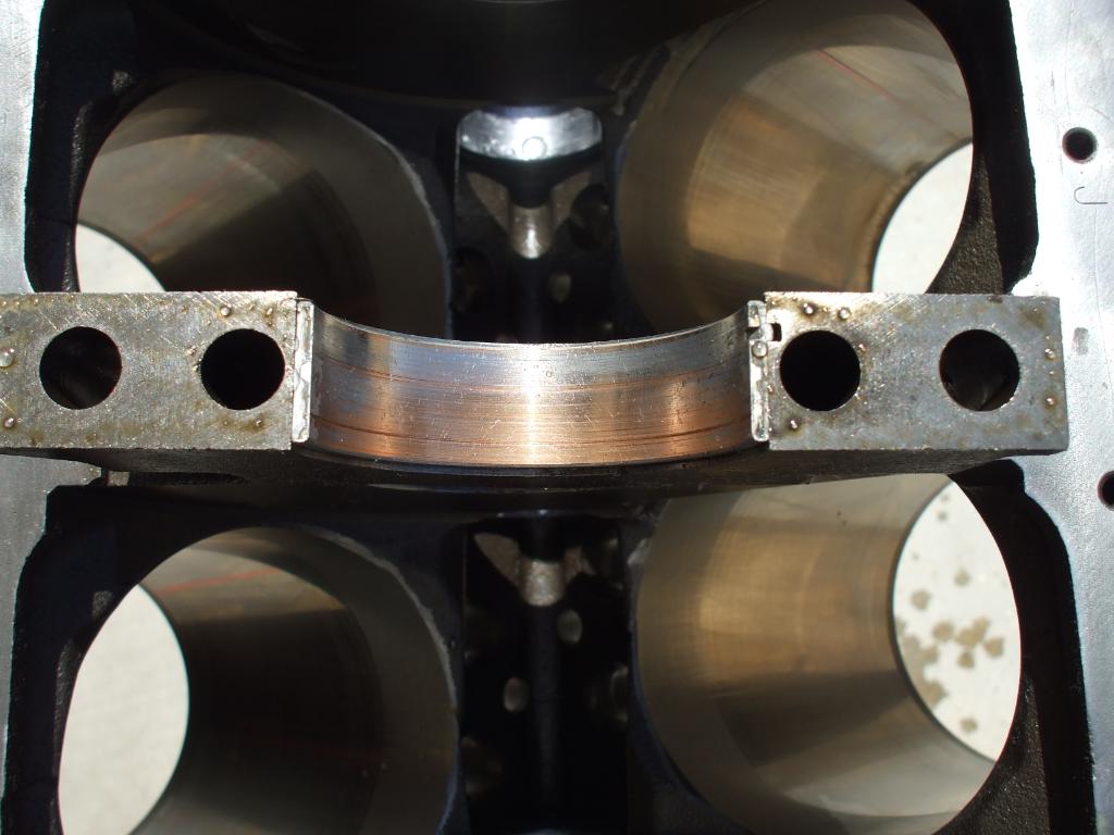
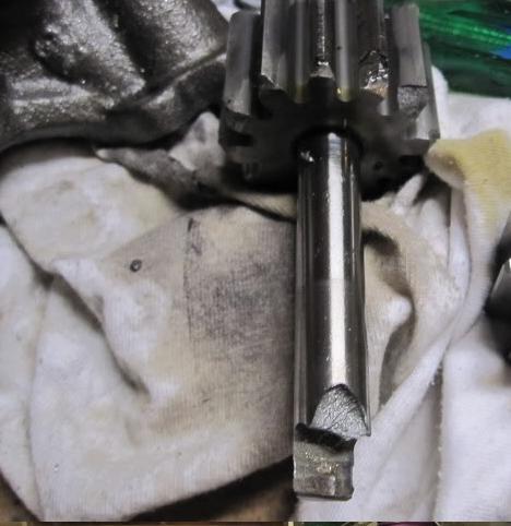
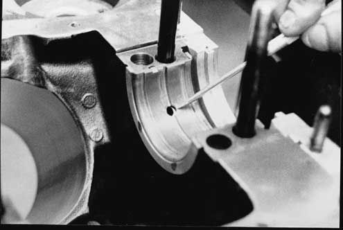
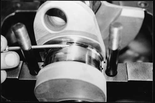
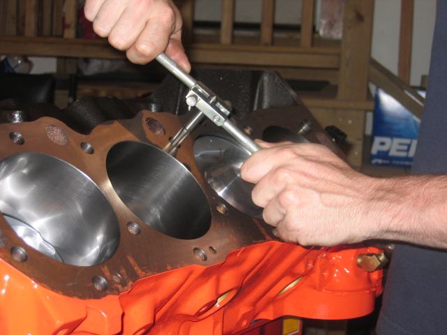
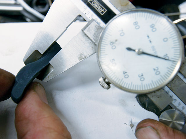
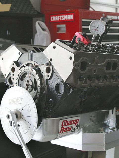
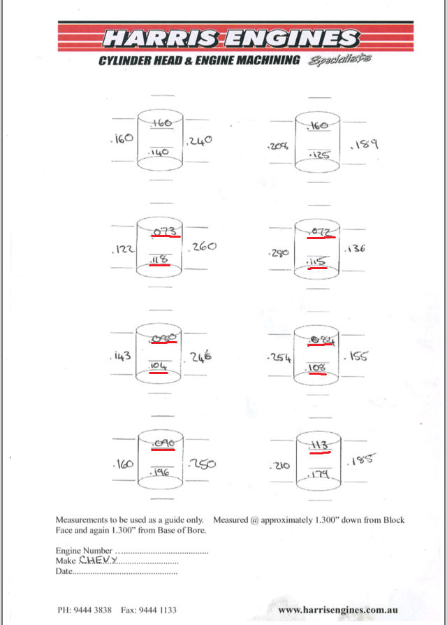
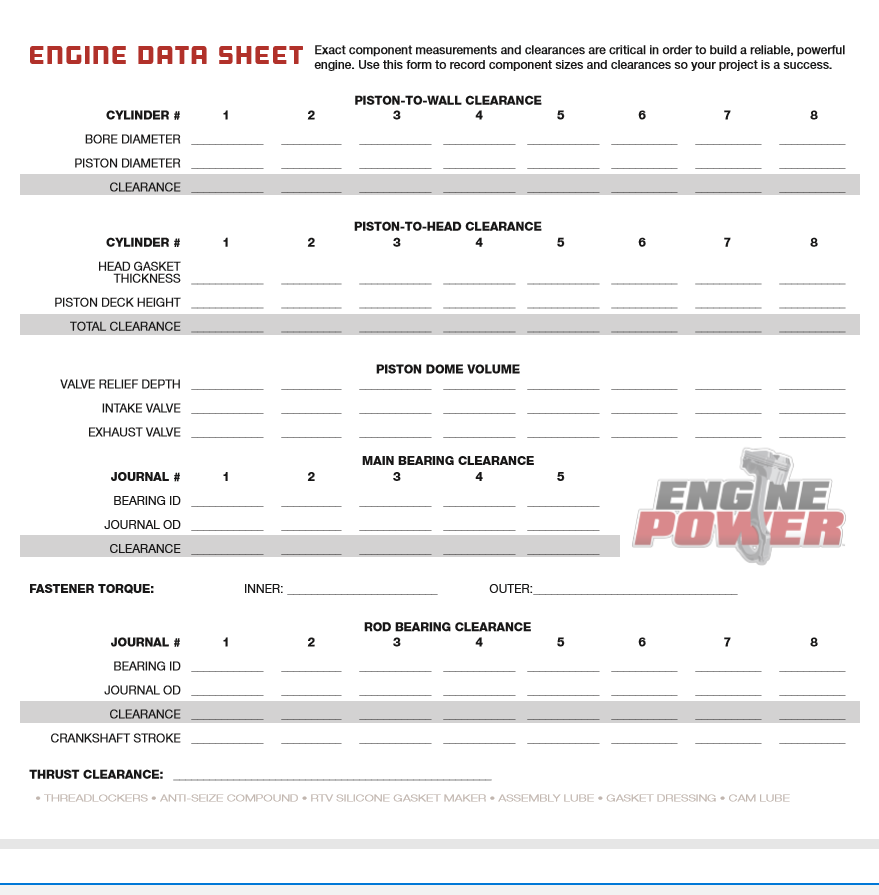
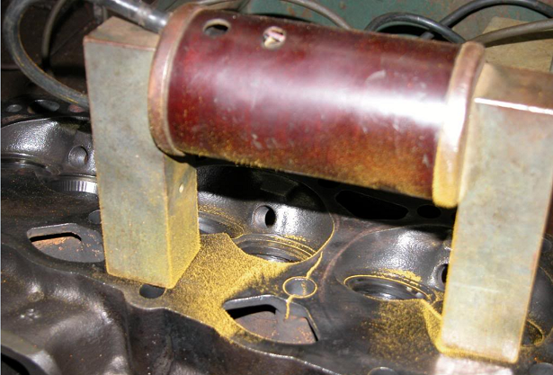
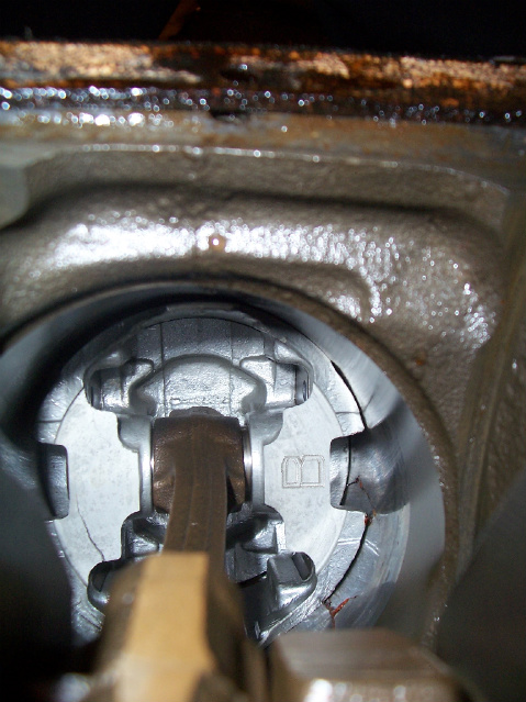
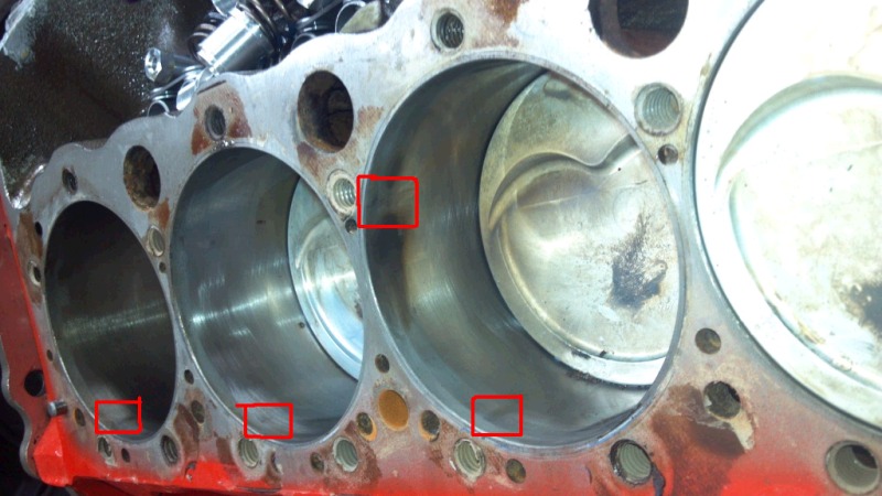
Here are the results from sonic testing. A few of the walls are thinner than .080 but according to machinist because of where they are it should be fine.

it's getting the following done:
- New core/welch plugs fitted
- New cam bearings
- Fully cleaned
- torque plate hone
- deck faces machined

Now I have to start organising parts.
I would like to purchase everything in one go through summitracing.com but if theres a place cheaper?

I will need verification that the parts list I order will be 100% compatible with my engine. I still have to choose a combo...


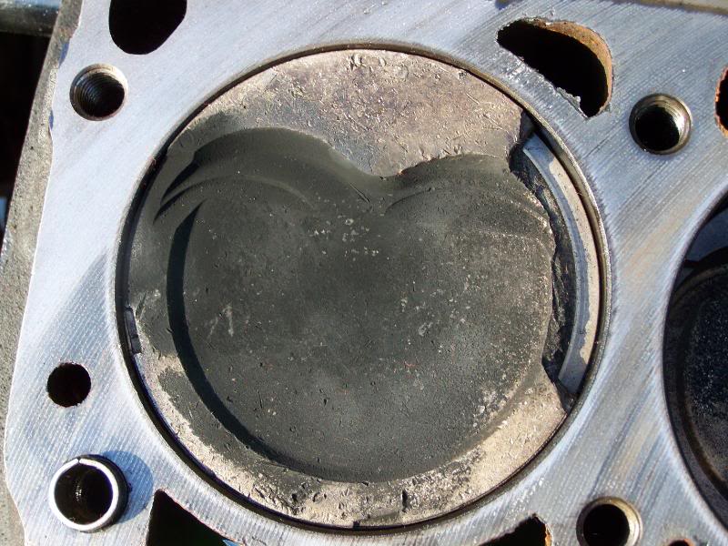
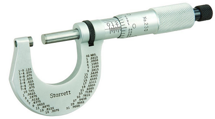
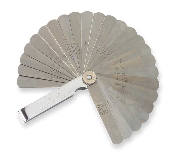
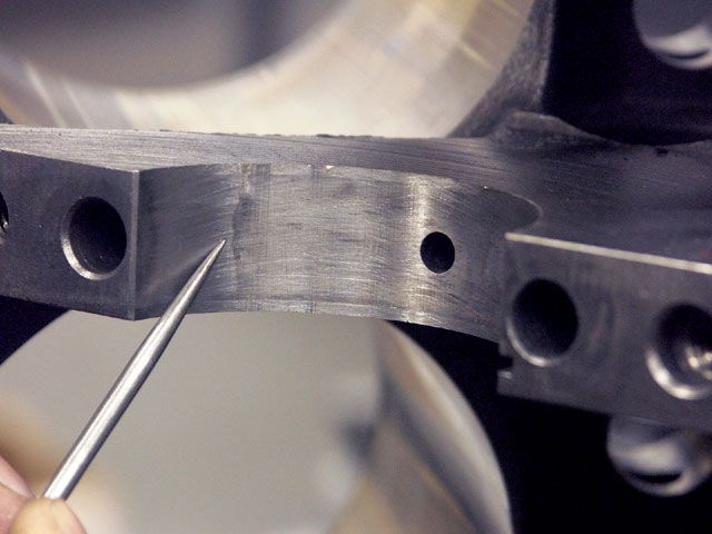
if your going to build a performance engine and your machinist is ok with .072 thick cylinder walls,you need a new machinist badly, get out a feeler gauge and look at what .072 looks like
before you dismiss this friendly advice get out a micrometer or feeler gauge and look at just how thin your sonic test results show your bore wall to be , and remember it will be hit with several hundred PSI pressure thousands of times an hour then think about how long it take you to bend a paper clip back and forth until it fails

starl.png

3R002_AS01.JPG


Engine Building Basics

There isn't a universal set of rules that govern all engine building. The following is information that has worked successfully and should be considered when building a performance engine.


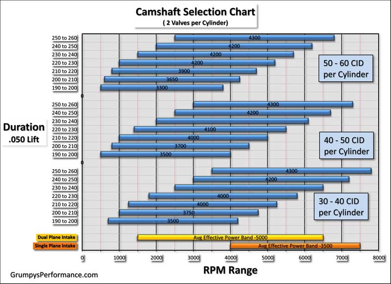
A high performance race engine, by its definition, indicates that limits are going to be pushed. The limit that is of most concern, as far as pistons are concerned, is peak operating cylinder pressure. Maximizing cylinder pressure benefits horsepower and fuel economy. Considering the potential benefit, owners of non-race engines, from motor homes to street rods, also look to increasing cylinder pressure. Increasing the compression ratio is one sure way of increasing cylinder pressure but its not the only way. Camshaft selection, carburetion, nitrous and supercharging can all alter cylinder pressures dramatically.

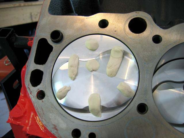
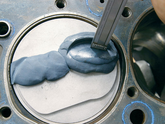
Excessive cylinder pressure will encourage engine destroying detonation with no piston immune to its effects. The goal of performance engine builders should be to build their products with as much detonation resistance as possible. An important first step is to set the assembled quench distance to .035". The quench distance is the compressed thickness of the head gasket plus the deck height, (the distance your piston is down in the bore). If your piston height, (not dome height), is above the block deck, subtract the overage from the gasket thickness to get a true assembled quench distance. The quench area is the flat part of the piston that would contact a similar flat area on the cylinder head if you had .000" assembled quench height. In a running engine, the .035" quench decreases to a close collision between the piston and cylinder head. The shock wave from the close collision drives air at high velocity through the combustion chamber. This movement tends to cool hot spots, average the chamber temperature, reduce detonation and increase power. Take note, on the exhaust cycle, some cooling of the piston occurs due to the closeness to the water cooled head.

If you are building an engine with steel rods, tight bearings, tight pistons, modest RPM and automatic transmission, a .035" quench is the minimum practical to run without engine damage. The closer the piston comes to the cylinder head at operating speed, the more turbulence is generated. Turbulence is the main means of reducing detonation. Unfortunately, the operating quench height varies in an engine as RPM and temperature change. If aluminum rods, loose pistons, (they rock and hit the head), and over 6000 RPM operation is anticipated, a static clearance of .055" could be required. A running quench height in excess of .060" will forfeit the benefits of the quench head design and can cause severe detonation. The suggested .035" static quench height is recommended as a good usable dimension for stock rod engines up to 6500 RPM. Above 6500 RPM rod selection becomes important. Since it is the close collision between the piston and the cylinder head that reduces the prospect of detonation, never add a shim or head gasket to lower compression on a quench head engine. If you have 10:1 with a proper quench and then add an extra .040" gasket to give 9.5:1 and .080" quench, you will create more ping at 9.5:1 than you had at 10:1. The suitable way to lower the compression is to use a dish piston. Dish (reverse combustion chamber), pistons are designed for maximum quench, (sometimes called squish), area. Having part of the combustion chamber in the piston improves the shape of the chamber and flame travel. High performance motors will see some detonation, which leads to preignition. Detonation occurs at five to ten degrees after top-dead-center. Preignition occurs before top-dead-center. Detonation damages your engine with impact loads and excessive heat. The excessive heat part of detonation is what causes preignition. Overheated combustion chamber parts start acting as glow plugs. Preignition induces extremely rapid combustion and welding temperatures melt down is only seconds away!

For a successful performance engine, use a compression ratio and cam combination to keep your cylinder pressure in line with the fuel you are going to use. Drop compression for continuous load operation, such as motor homes and heavy trucks, to around 8.5:1. Run a cool engine with lots of radiator capacity. Consider propylene glycol coolant and low temperature thermostats. Reduce total ignition advance 2 to 4 degrees. A setting that gives a good HP reading on a 5 second Dyno run is usually too advanced for continuous load applications. Normally aspirated Drag Race engines have been built with high RPM spark retard. The retard is used to counter the effect of increased flame travel speed with increased engine heat. "Seat of the pants" spark adjustment at low RPM will almost always cause detonation in mid to high compression engines once they are rung out and start making serious horsepower. Set spark advance to make best quarter mile speed not best ET, usually 34 degrees total advanced timing.

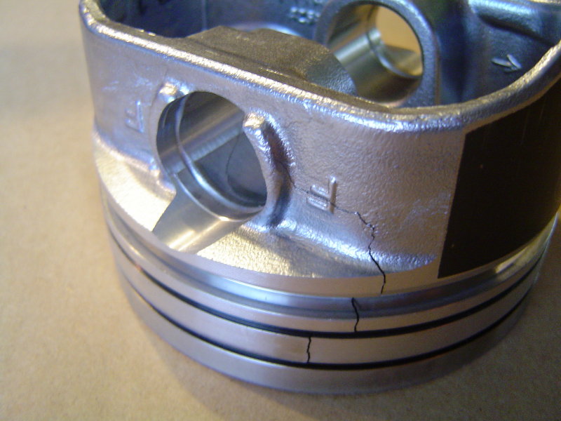
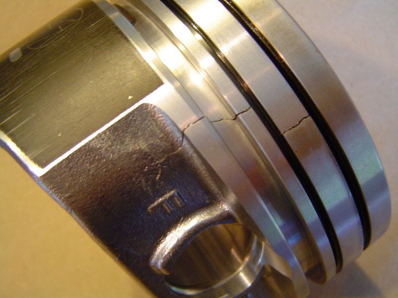
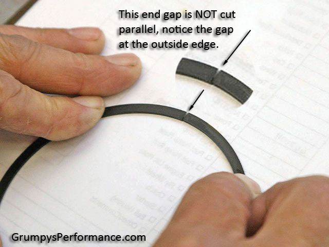
Top Ring End Gap is often a major player when it comes to piston problems. Top ring butting under high load and heat conditions can destroy the piston top land. Most top land damage on race pistons appears to lift into the combustion chamber. The reason is that the top ring ends butt and stick tight at top-dead-center. Crank rotation pulls the piston down the cylinder while leaving at least part of the ring and top land at top-dead. Actual end gap will vary depending on the engine heat load.


Lean mixture, excessive spark advance, high compression, low capacity cooling system, detonation and high HP per cubic inch all combine to increase an engine's heat load. Most new generation pistons incorporate the top compression ring high on the piston. The high ring location cools the piston top more effectively, reduces detonation and smog, and increases horsepower. If detonation or other excess heat situations develop, a top ring end gap set to the close side will quickly butt, with piston and cylinder damage to follow immediately. High location rings require extra end gap because they stop at a higher temperature portion of the cylinder at top-dead-center and they have less shielding from the heat of combustion. At top-dead-center the ring is above the cylinder water jacket.

If a ring end gap is measured on the high side, you improve detonation tolerance in two ways. One, the engine will run longer under detonation before rings butt. Two, some leak down appears to benefit oil control by clearing the oil rings of oil build up. Clean, open oil rings are necessary to prevent from reaching the combustion chamber, which is also why we do not like gapless rings. A very small amount of chamber oil will cause detonation and produce significant horsepower loss. Top ring gaps can be increased 50% with hypereutectic pistons.

Ring Options of 1/16" or stock 5/64" are offered on most performance pistons. The 1/16" option reduces friction slightly and seals better above 6,500 RPM, while being considerably more expensive. Stock, (usually 5/64" compression rings), work well and help with the budget.

Piston to Bore Clearance for hypereutectic pistons were Dyno tested at wide open throttle with .0015", .0020", .0035" and .0045" piston to bore clearance. After 7-1/2 hours the pistons were examined and they all looked as new, except the tops had normal deposit color. Even with 320 degrees Fahrenheit oil temperature, the inside of the piston remained shiny silver and completely clean. Excessive clearance has been shown to be safe with hypereutectic pistons. Loose Hypereutectic pistons over .0020" do make noise. As they get up to temperature they still make noise because they have very restricted expansion rate and do not swell up in the bore. The Hypereutectic alloy not only expands 15% less, it insulates the skirts from combustion chamber heat. If the skirt stays cool piston expansion is drastically reduced. Running close clearances is beneficial to piston ring seal and ring life. A small short term HP improvement can be had by running additional piston clearance because friction is reduced. To obtain actual piston diameter, measure the piston from skirt to skirt level with the balance pad.

Pin Oiling should be done at pin installation, whether it is pressed or full floating, prelube the piston pin hole with oil or liquid prelube, never use a grease. If you are using a pressed pin rod be sure to discard spiral pin retainers. A smooth honed pin bored surface with a reliable oil supply is necessary to control piston expansion. A dry pin bore will add heat to the piston rather than remove heat. Pistons are designed to run with a hot top surface, and cool skirts and pin bores. High temperature at the pin bore will quickly cause a piston to grow to the point of seizure in the cylinder.

Marine Applications require an extra .001"-.003" clearance because of the possible combination of high load operation and cold water to the block. A cold block with hot pistons is what dictates the need for extra marine clearance.

"Compression Ratio" as a term sounds very descriptive. However, compression ratio by itself is like torque without RPM or tire diameter without a tread with. Compression ratio is only useful when other factors accompany it. Compression pressure is what the engine actually sees. High compression pressure increases the tendency toward detonation, while low compression pressure reduces performance and economy. Compression pressure varies in an engine every time the throttle is moved. Valve size, engine RPM, cylinder head, manifold and cam design, carburetor size, altitude, fuel, engine and air temperature and compression ratio all combine to determine compression pressure. Supercharging and turbo-charging can drastically alter compression pressures.

The goal of most performance engine designs is to utilize the highest possible compression pressure without causing detonation or a detonation related failure. A full understanding of the interrelationship between compression ratio, compression pressure, and detonation is essential if engine performance is to be optimized. Understanding compression pressure is especially important to the engine builder that builds to a rule book that specifies a fixed compression ratio. The rule book engine may be restricted to a 9:1 ratio but is usually not restricted to a specific compression pressure. Optimized air flow and cam timing can make a 9:1 ratio but is usually not restricted to a specific compression pressure. Optimized air flow and cam timing can make a 9:1 engine act like a 10:1 engine. Restrictor plate or limited size carburetor engines can often run compression ratios impractical for unlimited engines. A 15:1 engine breathing through a restrictor plate may see less compression pressure than an 11:1 unrestricted engine. The restrictor plate reduces the air to the cylinder and limits the compression pressure and lowers the octane requirements of the engine significantly.

At one time compression pressure above a true 8:1 was considered impractical. The heat of compression, plus residual cylinder head and piston heat, initiated detonation when 8:1 was exceeded. Some of the 60's 11:1 factory compression ratio engines were 11:1 in ratio but only 8:1 in compression pressure. The pressure was reduced by closing the intake valve late. The late closing, long duration intake caused the engine to back pump the air/fuel mix into the intake manifold at speeds below 4500 RPM. The long intake duration prevented excess compression up to 4500 RPM and improved high RPM operation. Above 4500 RPM detonation was not a serious problem because the air/fuel mix entering the cylinder was in a high state of activity and the high RPM limited cylinder pressure due to the short time available for cylinder filling.


Before continuing with theory, a little practical compression information is in order. If you have a 10:1 engine with a proper .040" assembled quench and then add an extra .040" gasket to give 9.5:1 and .080" quench you will usually experience more ping at the new 9.5:1 ratio than you had at 10:1. Non quench engines are the exception to this rule. Some racers make the effort to convert non-quench engines to quench type engines, as with our Mopar Squish Deck Heads. Compression ratios that work are as follows:

PUMP FUEL

8.5:1- Non-quench head road use standard sedan, without knock sensor.

8.5:1- Quench head engine for tow service, motorhome and truck.

9.0:1- Street engine with proper .040" quench, 200° @ .050" lift cam, iron head, sea level operation.

9.5:1- Same as 9:1 except aluminum head used.

Light vehicle and no towing.

10:1- Used and built as the 9.5:1 engine with more than 220° @ .050" lift cam. A knock sensor retard is recommended with 10:1engines.

RACE GAS

12.5:1- Is the highest compression ratio suggested with unrestricted race gas engines.

ALCOHOL

15.5:1- Is the highest compression ratio suggested for unrestricted alcohol fuel engines.

Satisfactory use of 14:1 - 17:1 compression engines can be made when restrictor plate or small carburetor use is mandated by the race sanctioning. High altitude reduces cylinder pressure so if you only drive at high (above 4500 feet altitude) a 10:1 engine can be substituted for a 9:1 compression engine. General compression rules can be violated but is usually a very special case such as a 600 HP normally aspirated engine in a 1500 lb. street car with a 12:1 compression ratio. The radical cam timing necessary for this level of performance keeps low and medium RPM cylinder pressure fairly low. At high RPM detonation is less of a problem due to chamber turbulence, reduced cylinder fill time, and the fact that you just can't leave the above combination turned on very long without serious non-engine related consequences.

Piston temperature and horsepower are interrelated. High horsepower per cubic inch engines not only make more horsepower but they make more heat. How the excess heat is handled has a significant effect on total engine power and longevity.

Various piston, cam, valve, chamber and port configurations have been and are currently being tested to optimize engine internal temperatures. Some engines have ceramic exhaust port insulation coatings that allow cooler cylinder head operation while keeping exhaust temperatures elevated for efficient catalytic converter operation. The same ceramic type insulation on a piston top has been quite successful. Ideal piston temperatures in an operating engine would suggest refrigeration during the intake and compression stroke, and incandescence during the combustion and exhaust stroke. The advantage of a hot piston on the power stroke is that less combustion energy is going to be absorbed by the piston. So far, it is not practical to heat and refrigerate a piston 6000 times a minute. However, if the incoming air is not heated by the piston and the piston reflects the heat of combustion, you start to approach ideal conditions. A polished hypereutectic piston will reflect combustion heat back into the combustion process. This reflection, combined with the insulating qualities of the hypereutectic alloy, keeps the heat in the cylinder during the power stroke. A smooth polished piston runs cooler than a non-polished piston, even after combustion deposits have turned both pistons black. A cool, smooth piston will transmit a minimum of heat to the incoming fuel air mix.

The Hypereutectic piston gives the racer a real out of the box advantage with smooth diamond turned piston heads. A polish is relatively easy to achieve and does improve the already excellent reflectivity of the hypereutectic piston. If a buffing wheel is used, you will note a gray cast to the finished piston. The gray results from the exposure of the Silicon particles that are dispersed through the piston.

Experimental work to reduce piston heating of the incoming fuel mix has been very limited but, in theory, a thin ceramic coating may prove to be beneficial. A thin, smooth coating over a polished piston should still reflect combustion heat while reducing carbon buildup and protecting the piston polish. It is easier for a thin film to change temperature with each engine cycle than it is for the whole piston to do the same. A thin film can be cooled by the first small percentage of inlet fuel mix, allowing the main quantity of fuel mix to remain relatively cool. Tests have shown that polishing the combustion chamber, valves and piston top can increase horsepower and fuel economy by 6%.

All this polishing probably sounds counter to the practice of cimpling the combustion chamber. Dimpling has been show to put wet flow back into the air flow and improve combustion. We do not recommend dimpling, but do suggest cutting a small discontinuity close to the valve seat to turbulate wet flow. Some bench flowed cylinder heads encourage fuel separation at the inlet pot. If a small step is added at the valve seat to force the wet flow over the resulting sharp edge, fuel will reenter the air stream and give you the same affect as dimpling only without losing the benefit of a completely polished chamber. As you reduce wet flow you will improve combustion and most likely need to install leaner carburetor jets. Leaner jets compensate for the excess fuel that is available when wet flow is put back into the air/fuel mix. Significant additional horsepower gains can be had with careful attention to cylinder-to-cylinder fuel distribution by allowing all cylinders to be set "just right".

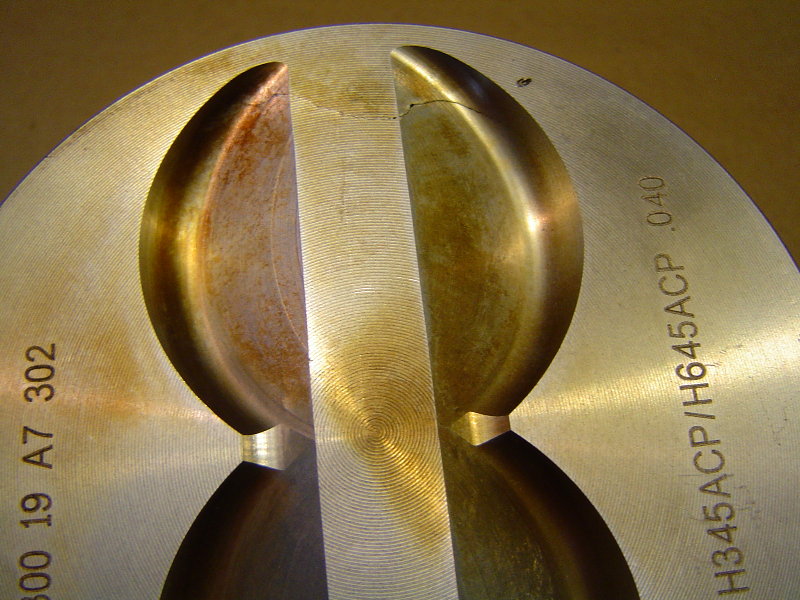
Combustion chamber design work has increased steadily the last ten years. Some of the work is mandated by the EPA and some is the result of race engine development. Some of the smog work has actually enhanced race engine development. Combustion chamber science is now more concerned with the effects of swirl, tumbling, shrouding of the valve, quench, flame travel, wet flow and spark location. A combustion chamber shaped dished piston can improve the flame travel in the combustion chamber. A dish allows the flame to travel further and expand more before it is stopped by a metal surface. This rapid flame travel makes it unnecessary to run big spark advance numbers. Ideally, we would like to be able to initiate ignition at top dead center since this would reduce negative torque in the engine that is now cause by spark advance. We are some time away from a practical spark ignition system that will make optimum power with a TDS setting. Some day it will happen. Don't go out and buy dished pistons for your open chamber 454. The advantage in flame travel is more than offset by the low compression ratio this combination yields. Small combustion chambers respond well to dished pistons, especially reversed dome or "D" cups. A 400 small block Chevy can use a 22CC D Cup piston and still have 10.4:1 compression. The trend in modern engine design seems to be smaller combustion chambers with recessed piston tops for more HP per cubic inch.

Ignition timing on most installations should be 34 degrees total with full mechanical advance dialed in. More advance may feel better off the line but the engine lays down as the combustion chamber components come up to temperature. At the drag strip set timing for maximum MPH not best ET. Too much spark advance will shorten the life of any performance engine, sometimes drastically.

Nitrous oxide can double the horsepower of most engines with less effort and money being spent than any other modification. Even the "smog people" are usually happy, as the nitrous is activated only during full throttle "open loop".

A nitrous engine can be built as a stock rebuild or it can be a dedicated effort to maximize the total performance package. As more power is generated, more waste heat, exhaust air flow and combustion pressures push the limits of engine strength. Often more beef is needed in the drive train and tires.

All stock factory engines are built with a safety factor when it comes to RPM, HP produced, cylinder pressure, engine cooling, etc. If you are only going to use a 100 HP nitrous setup on a 300 cubic inch or larger engine, built in factory safety factors are probably sufficient. As power output levels are raised engine modifications are usually prudent.

The most common mistake made when using nitrous oxide injection concerns ignition timing. A normally aspirated engine makes its best power when peak cylinder pressures occur between 14 and 18 degrees after TDC. Pistons usually require 34 degrees BTDC ignition timing at full mechanical advance to achieve proper ATDC peak cylinder pressure. The total time from spark flash to the point of peak pressure is typically 48 to 52 degrees. If an engine is producing 30% of its power from nitrous, the maximum cylinder pressure will occur too close to TDC to avoid run away to detonation. If ignition does not get retarded, good-bye horsepower and head gaskets. The key to getting max HP from a max nitrous engine is to shift the maximum cylinder pressure event progressively further after TDC.

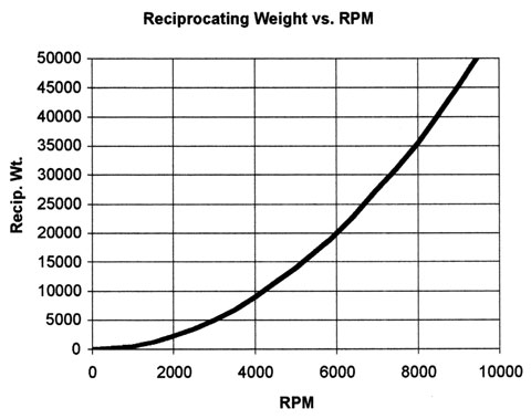
Cylinder pressure of 1000 PSI at TDC, (FIG. 1), can drop to 500 PSI with less than 3/8" of piston travel, (FIG. 2). If you can manage to get 1000 PSI in the same engine after the 3/8" travel, (FIG. 3), the pistons will have to travel an additional 3/4" to lower the cylinder pressure to 500 PSI, (FIG. 4). Work is defined as a force times distance. An average pressure, (750 PSI X 12-1/2 sq. in.), times distance in feet, (3/8" divided by 12), equals 293 foot pounds of work. Our second example, because it has twice the chamber volume above the piston location, must move twice as far to lower the cylinder pressure by 1/2. Since all the other numbers, by our own definition are the same, the force multiplied by a distance twice that of the first example will equal twice the work done, 586 foot pounds of work. There is no free lunch in horsepower equations because to get 1000 PSI above the piston in the second example takes twice as much fuel and energy as the 1000 PSI in the first example. What this offsetting of the peak pressure does is allow us to use the extra fuel mix available to a nitrous engine without breaking and melting things. The system that allows us to postpone maximum cylinder pressure is ignition timing retard. To a lessor extent short rod ratios, lower compression ratios, high RPM, aluminum heads, a tight quench, a rich fuel mixture, a small carburetor and hotter cams tend to delay maximum cylinder pressure.

Understand that, in our quest to delay cylinder pressure's peak time, more is not necessarily better. Instead, consider that the ideal cylinder pressure would be just short of detonation pressure and this pressure would be maintained from top dead center, and as long as possible after TDC. If timing is really late, you won't build enough cylinder pressure to start the car, let alone drive it. The 1000 PSI pressure in the example is not the maximum allowable combustion pressure but, rather, a comfortable pressure for illustration of the work principle.

Some nitrous manufacturers recommend, "retard the timing two degrees for each fifty horse power of nitrous". Other nitrous kits have the flame speed artificially slowed by the intentional use of a rich fuel to nitrous ratio. The maximum performance engine with a heavy nitrous load must achieve peak cylinder pressures, with the combustion chamber size being drastically increased due to the piston being on its way toward bottom dead center. The strongest engines have less compression ratio, less spark advance, and more nitrous.

Many people just don't like the idea of any retard. They say, "retard timing and exhaust heat goes up". It usually does in a stock non-nitrous engine because lower peak cylinder pressure slows the burning. If the timing is retarded in a non-nitrous engine, the exhaust opens before the fuel mix is finished burning and exhaust temperatures go up. Piston temperatures usually go down and exhaust valve temperature goes up. In the nitrous engine, exhaust temperature goes up for several reasons. The first is that the power output has gone up considerably. More power usually produces more waste heat. Second, the need to keep maximum cylinder pressures within reason has dictated that the biggest part of the fire happens closer to the exhaust valve opening time. There just isn't enough piston travel to extract all the energy out of the charge before the exhaust valve opens. Now, we could and sometimes do, open the exhaust valve later so more combustion pressure energy can be used to turn the crank. The trade off is negative torque on the exhaust stroke. If we still have significant cylinder pressure in the cylinder as the piston moves from BDC to TDC on the exhaust stroke, your net HP falls drastically. A real problem at higher RPM.

You can improve maximum power stroke efficiency and minimize exhaust pumping losses by running the engine at lower RPM and/or improving the exhaust valve size, lift and port design. A big nitrous engine likes everything about the exhaust to be big. If it flows good enough the cylinder will blow down by bottom dead center, even at high RPM with relatively mild exhaust valve timing. There are many variables in the design and development of an all out nitrous engine. A mistake will cause the melt down of any piston. The high strength of the hypereutectic piston will withstand detonation and severe abuse. Unfortunately, all pistons, even forged will melt and when cylinder pressure limits are exceeded, run away detonation can occur. The excess detonation heat makes the plugs, valves and pistons so hot the ignition system alone cannot be used to shut the engine down. Continued operation worsens the situation to the point of a total melt down. Designing a maximum performance nitrous engine is more of an exercise in heat management than it is in engine building. Serious nitrous users should review our list of ceramic coatings.

A lack of a sufficient fuel supply is probably the most common killer of the nitrous engine. If you add a 300 HP kit to your present 300 HP engine, your fuel requirements roughly double and a shortage doesn't just slow you down, it melts things. An electric fuel pump and fuel line devoted entirely to the nitrous equipment is recommended. If you are using a diaphragm mechanical pump to supply fuel to the carburetor, it is worth while to increase the fuel line I.D. If the carburetor goes lean while the nitrous is on, the pistons can melt even with a rich fuel line trick (1/2" dia.) only makes a major improvement in the operation of diaphragm mechanical pump is not recommended and does not do well at high engine RPM. A large size line is effective with a mechanical pump, even if you use smaller fittings at the tank, fuel pump and carburetor. The advantage of the 1/2" large line is not related to the steady state flow rate of the line.

The advantage relates to the acceleration time and displacement of the pulsating flow common to the mechanical pump.

High compression ratios can be used with nitrous but shifting the maximum pressure after top dead center becomes more and more difficult. I prefer to use street compression ratios and then just work with adding more nitrous to get desired horsepower levels.

We are currently testing some pistons specifically designed for Nitrous use. Current "off the shelf" pistons have been successfully run with a 500 HP nitrous kit combined with a nitrous control system. Most of our effort has been to develop new ideas that will push the limit of nitrous technology. More testing is planned with a piston especially coated to reduce detonation.

When choosing piston rings for an engine the most important factor is the intended use of the vehicle. A piston ring set that delivers excellent street performance may not be correct for an engine that will see competitive action, or for one that will be used with nitrous oxide.

Piston rings serve two purposes - to contain the cylinder pressure, and to prevent oil from getting into the combustion chamber. Sealing against pressure leakage, or "blow by", is the responsibility of the top ring. The keys to good ring sealing are cylinder wall finish and piston ring groove condition. If pressure gets past the top ring it is already "lost". Any such leakage will not be ignited by the spark plug, and is unlikely to produce any significant power, even if captured between the first and second ring. The second ring is primarily an oil control device. If the top ring is doing the job, the second ring will see fairly limited combustion pressure. Some companies sell second rings that use complex or fragile designs for sealing. These are prone to premature wear and have unpredictable behavior at high RPM levels. Cylinder leakage test percentages are only useful for comparison to data generated when an engine was fresh. Unfortunately this kind of information can be misrepresented to show very low leakage numbers by folks trying to sell "trick" parts. Leakage tests are steady state - they do not account for time, piston movement, or true operating pressures. "Blow-by" measurement will give a better picture of ring condition, but on track performance is the only real measurement of success. Our moly rings are intended for applications where cost is of prime importance.

Engines being built for serious competition will be far better off using Plasma Moly ring sets. These feature an extremely durable ductile iron top ring with Plasma Moly facing. This design allows the ring to seat quickly and to maintain its sealing integrity under the severe stress of racing. The second ring is a special low tension plain iron design. These taper faced rings are specifically designed to break in quickly and to keep oil from migrating into the combustion chamber. The SS50U stainless steel oil control rings are the absolute best in the high performance industry. This ring combustion gives dependable sealing and allows maximum power production.
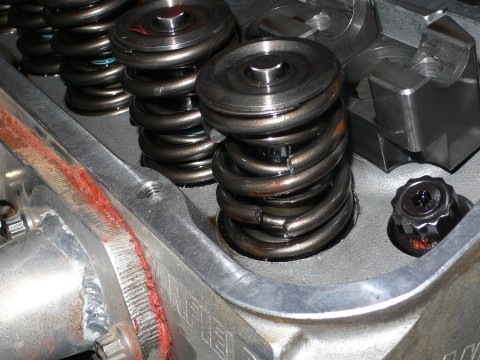
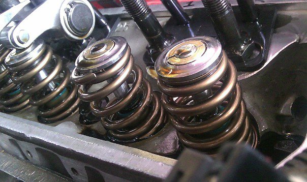
RING TENSION

Piston ring sets are available with either standard or low tension oil rings. The standard tension rings are recommended for street driven applications, and for race vehicles which may see frequent open to closed throttle transitions in use - such as road racing. They are also useful in engines that may experience cylinder bore distortion during operation.

Low tension oil rings deliver increased performance due to their reduction in cylinder wall drag. These are highly recommended for many racing applications. Engines using low tension rings should be built with particular attention to cylinder concentricity, and often benefit from the use of a crankcase vacuum system.

RING END GAP CLEARANCE

The piston ring's end gap can have a significant effect on an engine's horsepower output. Rings are available both in standard gap sets, and in special "file fit" sets. The file fit sets allows the engine builder to tailor the ring end gaps to each individual cylinder. Ring gaps should be set differently dependent upon the vehicles use, within the range of .003" (for the 2nd. ring) to .004" (for the top ring) per inch of cylinder diameter. The more severe the use, the greater the required end gap (assuming the use of similar fuels and induction systems). Engines having low operating temperatures, such as those in marine applications is too small. The chart below is a general guideline for cylinders with a 4.00" bore, adjust the figures to match your engine's cylinder diameter:

Top Rings (ductile iron, 4" bore)

Supercharged

Nitromethane .022 - .024"

Alcohol .018 - .020"

Gasoline .022 - .024"

Normally Aspirated - Gasoline

Street, Moderate Performance .016 - .018"

Drag Racing, Oval Track .018 - .020"

Nitrous Oxide - Street .024 - .026"

Nitrous Oxide - Drag .032 - .034"

2nd Rings (plain iron, 4" bore)

Supercharged

Nitromethane .014 - .016"

Alcohol .012 - .014"

Gasoline .012 - .014"

Normally Aspirated - Gasoline

Street, Moderate Performance .010 - .012"

Oval Track .012 - .014"

Pro Stock, Comp. .012 - .014"

Nitrous Oxide - Street .018 - .020"

Nitrous Oxide - Drag .024 - .026"

INSTALLATION NOTES -

CYLINDER WALL FINISH

When installing new rings, the single greatest concern is the cylinder wall condition and finish. If the cylinders are not properly prepared, the rings will not be able to perform as designed. The use of a torque plate, head gasket, and corresponding bolts are necessary to simulate the stress that the cylinder head will put on the block. Main bearing caps should also be torqued in place. The correct procedure has three steps. First the cylinder is bored to approximately .003" less than the desired final size. Next it is rough honed within .0005" of the final diameter. Then a finer finish hone is used to produced the desired "plateau" wall texture. Use a 280 - 400 grit stone to finish cylinder walls for Plasma Moly rings.

Note - the "grit" number we are referring to is a measurement of roughness, it is not the manufacturers stone part number (a Sunnen CK-10 automatic hone stone set #JHU-820 is 400 grit). The cylinder bores should be thoroughly scrubbed with soap and hot water and then oiled before piston and ring installation.

Piston ring grooves are also sealing surfaces, and must be clean, smooth and free of defects. Ring side clearance, measured between the ring and the top of the groove, should be between, .001" and .004".

SPECIAL! THANKS TO JOHN ERB CHIEF ENGINEER AT UNITED ENGINES


egcl1.png

egcl2.png


the first few rule's of GRUMPY'S engine assembly

(1) THINK THINGS THROUGH CAREFULLY ,
WRITE DOWN A LIST OF COMPONENTS ,

MAKE DARN SURE THE LIST IS COMPATIBLE WITH,
and AT LEAST SEMI-REASONABLY PRICED WITHIN YOUR BUDGET.
FOR WHAT YOU INTEND TO BUILD AND RESEARCH THE RELATED MACHINE WORK,

RESEARCH CAREFULLY THE COMPONENT INSTALLATION AND INTENDED USE ,
AND POWER BAND THE PARTS WILL REQUIRE

AND FIND AN EXPERIENCED MENTOR.

(2) if in doubt, about how to do anything, on an engine, do some detailed research,
find and compare at least 3-5 valid trust worthy sources info,
read the instructions over again, several time's very carefully
and if available watch several related videos.

(3) if any component will not easily function as designed or requires a good bit of physical force to install ,
or your not 100% sure your doing something CORRECTLY

STOP, FIND OUT EXACTLY HOW THE PARTS SUPPOSED TO FIT AND FUNCTION,& WHY! YOUR HAVING PROBLEMS
theres a reason, and you better verify your clearances are correct , and your following the instructions before you proceed.

(4) never assume the parts you purchased can be used without carefully , cleaning them prior too,
checking the physical condition, verifying clearances and using the correct sealant, lubricants etc.


(5) the quality of a component is generally at least loosely related to the cost to produce it,
and the amount of detailed research and quality machine work that went into its production.
if you got a significant reduced price, theres typically a reason.
it might simply be because a new improved part superseded the one you purchased,
but it might be a far lower quality imported clone with lower quality materials and machine work.
its the purchasers responsibility to research quality.

(6) if you did not do the work personally or at least take the effort to verify it was done correctly and personally verify clearances

ITS almost a sure thing that it was NOT done , correctly, and yes that mandates you fully understand what your looking at,
and how the components are supposed to function and have high quality precision measuring tools.

(7) ITS ALMOST ALWAYS FASTER AND LESS EXPENSIVE , AND PRODUCES BETTER RESULTS IF YOU,
BUY FEWER HIGH QUALITY PARTS & DO THINGS CORRECTLY THE FIRST TIME
 
Last edited by a moderator:
Why do Production Small Block Chevies have so much core shift & thin spot cylinder walls Grumpy ?
Its an economical layout.
But to go Racing you need a stockpile of blocks to sonic check or plan on Hard Blocking it to begin with.
Or cough up the $$$ fir a Dart Little M Block.
Big Blick Chevies have better reputation for thick walls.
Pontiacs are at least .250-..300" thick walled all.
1964-65 389 Poncho has .400-.500" thick walls.
Olds 455 You can bore over .125" & still have .150-.180' thick walls.
Even Smog 403 has decent thick walls with hollowed out main webs.
 
87vette81big said:
Why do Production Small Block Chevies have so much core shift & thin spot cylinder walls Grumpy ?
Its an economical layout.
But to go Racing you need a stockpile of blocks to sonic check or plan on Hard Blocking it to begin with.
Or cough up the $$$ fir a Dart Little M Block.
Big Blick Chevies have better reputation for thick walls.
Pontiacs are at least .250-..300" thick walled all.
1964-65 389 Poncho has .400-.500" thick walls.
Olds 455 You can bore over .125" & still have .150-.180' thick walls.
Even Smog 403 has decent thick walls with hollowed out main webs.

less .072" is barely thicker than a dime (dimes are .054")

a square matchstick like you would use for the BBQ is about .080" wide... you expect that to tolerate any kind of power? i think not!
 
No Phil.
Sleeving required. Hardblocked 1" from top of deck.
Not worth it. Throw block away.
I like Chevies too. But some things made not so great.
Just Cheap.
Like that crap Dana 36 & Dana 44 in our C4 Corvettes.
 
"This is my second go around with this company regarding a performance 383 motor. They are replacing the first 383 roller cam motor I bought which turned out to be a total disaster (poor machine work to include .010 inches difference in deck height from left bank to right bank, a re-sleeved and welded block, amongst other things.)"
Every time I read of an experience like this I wonder why people trust others to do something that is basically no more difficult than what my grandkids do when they make something out of legos. If a person wants to rebuild an engine it's no more complicated than finding a core on Craigslist or at a local Chevy/GMC dealer who has just installed a replacement engine and having some machine work done. Then after the parts are machined and cleaned they are checked to verify dimensions, then assembled. That eliminates the problems quoted above and also creates the satisfaction of a job well done every time we mash down on the accelerator.

The money saved at $100/hr charged to do a sloppy engine assembly is an added bonus.

Ray W


your correct that theres a lot of low quality workmanship and parts for sale and the more detail work you can do yourself, AND the better your ability is to know the difference between quality machine work and slapped together parts ,and the less you have to trust some stranger that in many cases just doesn,t care how your engine project turns out,
that skill comes from EXPERIENCE,
spending time RESEARCHING what needs to be done,
why it needs to be done and
HOW its done correctly and
having a few basic tools so you can inspect and accurately measure machine work.
youll need a cheap but fairly sturdy basic engine stand to get the work off the floor,and being able to carefully inspect the components selected and used in the careful assembly process,sure reduces the chances of problems later
22556.jpg

a few basic tools and a good understanding of what your doing


http://garage.grumpysperformance.com/index.php?threads/tbucket-engine-project-dart-shp.3814/

http://garage.grumpysperformance.co...-engine-stand-mods-accesories.3724/#post-9667

http://garage.grumpysperformance.co...g-and-installing-connecting-rods-pistons.247/

http://garage.grumpysperformance.com/index.php?threads/bare-minimum-tools.11026/#post-51823

http://garage.grumpysperformance.com/index.php?threads/matching-parts-and-a-logical-plan.7722/

http://garage.grumpysperformance.com/index.php?threads/what-to-look-for-in-a-good-engine-combo.9930/

http://garage.grumpysperformance.com/index.php?threads/tips-on-building-a-383-sbc-stroker.428/

http://garage.grumpysperformance.com/index.php?threads/finding-a-machine-shop.321/

http://garage.grumpysperformance.co...ty-thats-key-in-building-a-good-engine.11682/
 
Last edited:
heres a list of services, or steps in an engine build,
an engine builder listed ,
you may want too look it over as a memory jogger,
obviously you may not need to do everything listed and you might have other things too add but,
reading through the list,
it may help you not ignore or skip something important you might miss.

be aware that head bolts enter the block coolant passages,
so if you failed to dip the bolt threads in sealant when they were assembled,
through the heads coolant can seep up along the head bolts,
into the area under the valve cover

btw read this
clean any block you buy and look for obvious cracks and if you have doubts get the machine shop to mag or dye test the block or heads
lifter bores
and lifter gallery

,piston bore walls,
block main cap web support areas
heads between the valves in valve seat area

look for stripped head and manifold and oil pan mounting bolt threads,
in threaded holes and cracks in block radiating from the holes
blockcr1.jpg

blockcr2.jpg
blockcr3.png
blockcr4.jpg

blockcr5.jpg

blockcr6.jpg
blockcr7.jpg

blockcr8.jpg


80057.jpg

80063.jpg


both of these work great at sealing head bolt threads,
• Disassemble, wash and inspect parts

• Crack check using Magnaflux (ferrous metals) or Zyglo (non-ferrous metals) if necessary

• Chase all threads in cylinder case and clean

• Measure main bores, line hone if necessary

• Measure lifter bore clearance

• Measure cylinder bore

• Hone cylinder bores using deck plates

• Measure bore finish with profilometer

• Weigh pistons, connecting rods, rod bearings, pins, locks and rings to determine crankshaft bobweight

• Balance crankshaft

• Polish crankshaft journals

• Tack weld crankshaft trigger wheel

• Hone piston pin bores and connecting rod small end

• Polish piston pins (excl. DLC-coated pins)

• Deburr piston round wire locks

• Measure ring lands for back clearance

• Deburr piston ring ends

• Gap piston rings

• Measure main journals with air gauge

• Measure big end of connecting rods with air gauge, hone if necessary

• Size main bearings with air gauge

• Measure connecting rod bolt stretch

• Size rod bearings with air gauge

• Measure crankshaft endplay

• Measure piston pin endplay

• Measure connecting rod side clearance

• Check piston to deck height

• Deck block if necessary

• CC piston dome volume

• CC cylinder head chamber volume

• Deck heads if necessary

• CC intake port volume

• CC exhaust port volume

• Measure valve guide clearance

• Measure valve spring pressure and coil bind

• Check valve spring retainer to seal clearance

• Polish camshaft

• Measure camshaft specs with EZ Cam

• Degree camshaft

• Measure piston-to-valve clearance

• Measure valve radial clearance

• Measure vertical valve drop

• Measure camshaft endplay

• Measure lifter preload to determine pushrod length

• Calculate compression ratio

• Torque all fasteners to spec

• Document all measurements and torques in engine build book

• Perform engine dynamometer validation

o Break-in using specific schedule


o Verify power and torque

o Document in dyno report


Other capabilities as needed:

• Hot hone (cylinder bore honing at operating temperature)

• Piston ring land flatness measurement to the millionth of an inch

• Hardness testing

• Bore cylindricity measurement using PAT Incometer

• Valvetrain dynamics testing

• Cylinder head flow testing

• Dynamometer durability testing and track simulation

• Engine calibration (MEFI4)
DART BIG M BBC BLOCK
Features:
  • Siamesed Extra-Thick Cylinder Walls: Resists cracking and improves ring seal (minimum .300'' thick with 4.625'' bore).
  • Scalloped Outer Water Jacket Walls: Improves coolant flow around the cylinder barrels to equalize temperatures.
  • Four-Bolt Main Bearing Caps: In steel or ductile iron have splayed outer bolts for extra strength.
  • Crankshaft Tunnel: Has clearance for a 4.500'' stroke crank with steel rods without grinding.
  • True ''Priority Main'' Oil System: Lubricates the main bearings before the lifters.
  • Oil Filter Pad: Drilled and tapped for an external oil pump.
  • Rear Four-Bolt Cap: Uses standard oil pump and two-piece seal - no adapter required!
  • Lifter Valley Head Stud Bosses: Prevent blown head gaskets between head bolts.
  • External Block Machining: Reduces weight without sacrificing strength.
  • Simplified Install : Fuel pump boss, clutch linkage mounts and side & front motor mounts simplfy installation on any chassis.
  • Dual Oil Pan Bolt Patterns: Fits standard and notched oil pans.
  • Bellhousing Flange and Rear Main Bearing: Reinforced with ribs to resist cracks.
  • Note: Does not include cam bearings, freeze plugs, or dowels
 
Last edited:
Back
Top