HEY GRUMPY??? can you give a bit more info on this chart?
http://www.youtube.com/watch?v=wzKtaDke22k
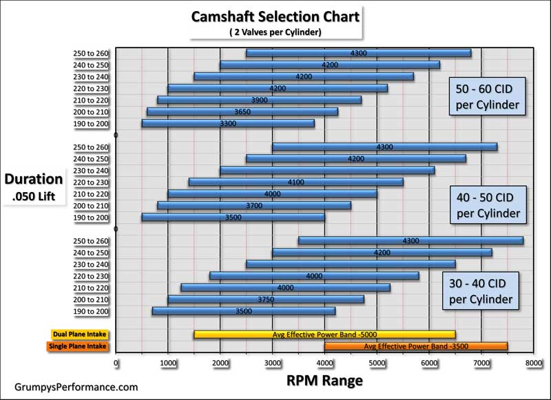
heres a chart I found that I don,t fully agree with, I think its a bit conservative, by about 3%-5% on the required cam duration ,required to avoid detonation with todays crappy octane fuel, but it at least gives you a base to work from, but Id suggest selecting a bit more duration
thats a great chart! Indycars, did the work, and did a great job!
its simply a rough guide to give you a starting point,in your calculations for a street performance combo using normal pump octane fuel. obviously port size rear gearing etc. need to be considered also. its not meant to be exact but combined with other info it should help keep your choices rational. lets say you have a typical 454 chevy
thats about 57 cubic inches per cylinder
so you look at the top set of rpm range bars to find the average power band you prefer to operate in, then look on the left side to get a cam intake at .050 lift duration range
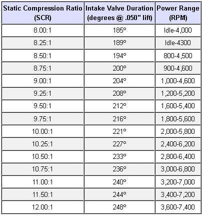
your dynamic compression with that cam should be close to 8:1 when selecting the compression of the engine. the power range bars do not indicate the engine won,t operate above or below that rpm range only that the blue bare shows the preferred operational range
combined with other info and charts it helps you make better choices
now look below at the intake suggestion, band, which intake covers more of your power band
this whole sections full of related info there for you guys to easily access
http://forum.grumpysperformance.com/viewforum.php?f=52
you can use the comp cam selection program to verify trends
http://www.camquest.com/
you can use this program to narrow results down even further
http://www.auto-ware.com/software/eap/eap.htm
I read somewhere that using 1.6 rr adds to duration is there truth to this?
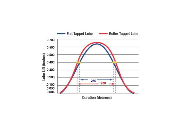
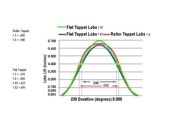
technically YES you add about 1-2 degrees effective duration,because the valve accelerates off its seat faster and the valves open both longer and a bit further off the seat, but look at the charts below, if measured even at .100 lift, the difference in duration is very minimal, but pragmatically the increase is so small its nearly meaningless in how the engine runs.
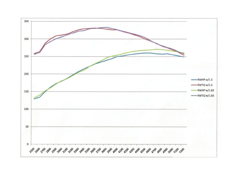
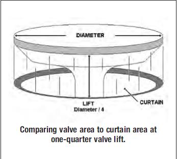
Higher ratio rocker arms may show more of a hp gain ,. You are gaining more of a flow "curtain" or window, more quickly, as the valve accelerates off the seat slightly faster with the higher ratio rocker,. In the case of the SBC many times the best gain is found by using 1.6:1 rockers on the intake side only, and retaining 1.5s on the exhaust. One thing to consider is that by using higher ratio rocker arms, you are also increasing the effective cam duration,very slightly and increasing the engines ability to breath marginally, but in most cases swapping to a larger cam and retaining the 1.5:1 RATIO ROCKERS HAS MORE POTENTIAL POWER, BUT THE 1.6:1 ratio swap is far easier to do and a good tuning tool.
AS A GENERAL RULE YOU WILL ALMOST ALWAYS GAIN MORE FROM, A SWAP TO A SIMILAR DURATION ROLLER CAM OR A SLIGHTLY TIGHTER LSA ROLLER CAM WITH ITS MORE AGGRESSIVE RAMPS THAN FROM A ROCKER SWAP ON A FLAT TAPPET CAM
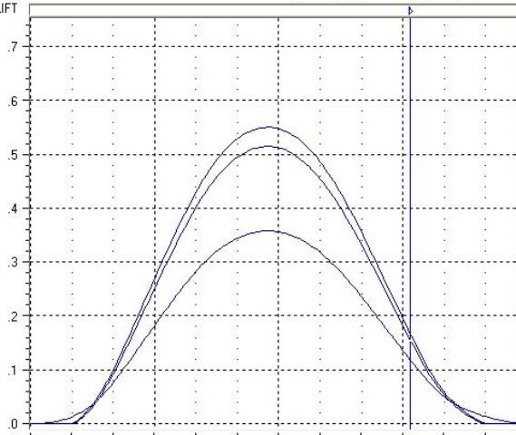
notice the change in duration is minimal but the area under the lift curve has improved insuring the flow or curtain area has improved,
http://www.pontiacstreetperformance.com ... rArms.html
Higher Ratio Rocker Arms
by Jim Hand, July 1999
[This article originally appeared on Eric Douthitt's, The Pontiac Garage,
website. It now appears here courtesy of the author and Eric Douthitt.]
What are the overall effects of higher ratio rockers? Do they add stress to the engine? Are they safe to use? Do they add power? What precautions should be considered before installing them? The following is a summary addressing these questions.
The basic valve train consists of a cam, or cam lobe, some sort of cam follower, such as a lifter, a push rod, a rocker arm, and the valve (with the associated retainer/keepers, and valve springs). The cam lobe lift is dictated by the dimension from the base circle of the lobe to the lobe centerline, or peak of the lobe. The base circle must be kept large enough to not degrade the strength of the cam, while allowing for enough lift (in conjunction with the rocker arm) to meet all design goals. Obviously, the peak lift of the lobe cannot be higher then the outer diameter of the cam bearings - otherwise, the cam could not be installed. So, in cam design, as more lift is designed in, the base circle becomes smaller in diameter. As the obtainable lift is limited, the lift is multiplied by the rocker arm ratio to bring it up to the desired point(s). If we used rocker arms that had a 1 to 1 ratio, the valve would follow the exact opening and closing as the cam lobe - same peak lift, same opening and closing rate, and same limited valve open area. By making the rocker some greater ratio, such as the standard 1.5, the lift of the lobe is multiplied by 1.5, the opening and closing rates are much faster, and the area under the overall "curve" is much greater. This becomes very obvious by reviewing the graph.
The cam is rated at some duration at .050 lifter/tappet rise. This of course cannot be changed and will remain the same regardless of the rocker arm ratio. However, the valve lift is normally specified with standard 1.5 ratio rocker arms. This can be changed by installing different ratio rockers. As a 1.65 ratio rocker is 10% higher ratio then a 1.50, the lift provided by the 1.65 rocker will be 10 % greater with all cams. This also can be seen on the attached graph. Note that the graph shows a 1.72 ratio rocker, but the action is similar between various ratios. What happens to valve open time with the higher ratio rockers? Because the higher ratio rocker lifts the valve to a higher point in the same time period, it has to lift both quicker and steeper. As the valve begins to open at the same point regardless of rocker ratio, and it opens at the same time as the cam lobe, the duration of the valve opening in crankshaft degrees at the initial opening and closing points is identical to the cam lobe duration. However, because of the quicker and steeper opening/closing rates, the valve open time is greater from any point after initial opening when a higher ratio rocker is used. This is also obvious on the graph. How much more duration? I devised a method to actually measure it. As a standard lobe measuring point is .050 lifter rise, and lobe lifts are normally specified with 1.5 rocker ratio, that means the valve will always be at .075 when the lobe reaches .050" lift (when a 1.5 rocker is installed). By using the .075 point, and determining where it occurs in relationship to the crank in degrees, a yardstick is provided from which to reference any different rocker ratios. As expected, a higher ratio rocker will allow the valve to reach the .075 lift point earlier in the lift cycle (and later in the closing cycle). As the .075 valve lift point is the industry standard when specifying cam duration (1.5 standard rocker ratio X .050 tappet/lifter rise), it becomes a valid reference point. In the Wolverine 234 degree intake lobe, the intake valve was open 4 to 5 degrees longer when measured in reference to the crank when the larger ratio rockers were used. This is also easy to see on the graph.
Summary:
Higher ratio rocker arms open the valve faster, higher, and hold it open for a much greater total period of time as compared to lower ratio units. Does this cause more stress on the valve train? There will be more pressure on the cam lobes due to the friction and pressure caused by the higher lift and resultant greater spring load. However, as compared to providing the same higher lift and effective longer duration with a more radical cam and even stiffer springs, the higher ratio rockers may create less total valve train stress. And such a cam lobe would be very aggressive and would require much heavier springs to keep the lifter from flying off the lobe. Very radical lobes will also add more side stress on the lifters/bores and could possibly cause lifter bore failure. The added pressure on the studs from either higher ratio rockers, or more radical lobe, will be well within the capabilities of modern after market studs.
Safety:
Some precautions are needed when using higher lift rockers. The valve springs must be able to handle the increased lift. Otherwise, spring bind may occur and that will cause serious engine damage. On very high lift setups, or unusually tight lobe separation or advanced intake lobe cams, valve to piston interference must be checked. As the mechanical aspects of different ratio rockers vary, the position of the push rod in relation to the stud may change. Higher ratio units typically have the push rod depression in closer to the stud, and that may cause interference at the tops of the push rod holes in the heads. This clearance must be checked. Higher lift units may cause interference with the rocker covers. This problem can be handled with extra cover gaskets, cover spacers, or even special covers.
More Power? This is the really big question and the answer varies with different applications. As we know, an engine runs best within a given rpm range with an ideal cam - correct lift, duration, and lobe placement. If we have that ideal and perfect cam installed, higher ratio rockers will not help performance. In most cases, we don't have the ideal cam, and additional lift and/or additional duration might help performance. As it is quite easy to install rockers, providing all safety points mentioned above are met, direct testing can be conducted with any engine. I maintain and have proven to my satisfaction that higher ratio rockers can provide the same benefits as more exotic cams but without the excessive costs. The secret to any engine's performance is to obtain maximum area under the valve open curve with the minimum overlap and mildest valve train action, again assuming the open time occurs at the optimum time. High ratio rockers accomplish that due to their complex effect on the valve train dynamics. If we would compare two cams of equal duration and lobe positions, but one with more lift on the lobe and 1.5 ratio rockers, and the second with less lobe lift but higher ratio rockers to equal the lift of the first, the milder lift cam with higher lift rockers will always provide more performance (again providing the cam is not to large to begin with).
Rocker Arm Ratios:
Do not assume rockers are the actual rated lift ratio. Example: My Pontiac 1.5 flat rockers measure an average of 1.48, and a set of original Pontiac 1.65 rockers measure an average of 1.61. A set of 1.6 rated rollers from Jim Butler measured 1.61, and a set of Harland Sharp 1.65 rollers measure 1.75. All of these measurements were made with a lightweight checking spring, and do not represent actual ratio under the normal spring loads of 260 to 600#. We could expect these ratios to diminish as heavier springs are used. The representative from Harland Sharp states that the HS 1.65 Pontiac rollers are "only" 1.70 when measured with a 550# spring load. I suspect my stock push rods would do a real contortionist act with 550# valve springs, but we have to remember that the big rollers require this level of pressure.
more related info
http://www.wallaceracing.com/rockercalc.php
viewtopic.php?f=52&t=198
viewtopic.php?f=52&t=506
viewtopic.php?f=52&t=126
http://www.chevyhiperformance.com/techa ... index.html
http://www.carcraft.com/techarticles/11 ... ewall.html
http://www.popularhotrodding.com/tech/0 ... hrods.html
viewtopic.php?f=52&t=1070
viewtopic.php?f=52&t=181
viewtopic.php?f=52&t=82&p=105#p105
http://www.popularhotrodding.com/engine ... ewall.html
http://www.highperformancepontiac.com/t ... ewall.html
http://www.vetteweb.com/tech/0204vet_sm ... index.html
http://www.youtube.com/watch?v=wzKtaDke22k
heres a chart I found that I don,t fully agree with, I think its a bit conservative, by about 3%-5% on the required cam duration ,required to avoid detonation with todays crappy octane fuel, but it at least gives you a base to work from, but Id suggest selecting a bit more duration
thats a great chart! Indycars, did the work, and did a great job!
its simply a rough guide to give you a starting point,in your calculations for a street performance combo using normal pump octane fuel. obviously port size rear gearing etc. need to be considered also. its not meant to be exact but combined with other info it should help keep your choices rational. lets say you have a typical 454 chevy
thats about 57 cubic inches per cylinder
so you look at the top set of rpm range bars to find the average power band you prefer to operate in, then look on the left side to get a cam intake at .050 lift duration range
your dynamic compression with that cam should be close to 8:1 when selecting the compression of the engine. the power range bars do not indicate the engine won,t operate above or below that rpm range only that the blue bare shows the preferred operational range
combined with other info and charts it helps you make better choices
now look below at the intake suggestion, band, which intake covers more of your power band
this whole sections full of related info there for you guys to easily access
http://forum.grumpysperformance.com/viewforum.php?f=52
you can use the comp cam selection program to verify trends
http://www.camquest.com/
you can use this program to narrow results down even further
http://www.auto-ware.com/software/eap/eap.htm
I read somewhere that using 1.6 rr adds to duration is there truth to this?
technically YES you add about 1-2 degrees effective duration,because the valve accelerates off its seat faster and the valves open both longer and a bit further off the seat, but look at the charts below, if measured even at .100 lift, the difference in duration is very minimal, but pragmatically the increase is so small its nearly meaningless in how the engine runs.
Higher ratio rocker arms may show more of a hp gain ,. You are gaining more of a flow "curtain" or window, more quickly, as the valve accelerates off the seat slightly faster with the higher ratio rocker,. In the case of the SBC many times the best gain is found by using 1.6:1 rockers on the intake side only, and retaining 1.5s on the exhaust. One thing to consider is that by using higher ratio rocker arms, you are also increasing the effective cam duration,very slightly and increasing the engines ability to breath marginally, but in most cases swapping to a larger cam and retaining the 1.5:1 RATIO ROCKERS HAS MORE POTENTIAL POWER, BUT THE 1.6:1 ratio swap is far easier to do and a good tuning tool.
AS A GENERAL RULE YOU WILL ALMOST ALWAYS GAIN MORE FROM, A SWAP TO A SIMILAR DURATION ROLLER CAM OR A SLIGHTLY TIGHTER LSA ROLLER CAM WITH ITS MORE AGGRESSIVE RAMPS THAN FROM A ROCKER SWAP ON A FLAT TAPPET CAM
notice the change in duration is minimal but the area under the lift curve has improved insuring the flow or curtain area has improved,
http://www.pontiacstreetperformance.com ... rArms.html
Higher Ratio Rocker Arms
by Jim Hand, July 1999
[This article originally appeared on Eric Douthitt's, The Pontiac Garage,
website. It now appears here courtesy of the author and Eric Douthitt.]
What are the overall effects of higher ratio rockers? Do they add stress to the engine? Are they safe to use? Do they add power? What precautions should be considered before installing them? The following is a summary addressing these questions.
The basic valve train consists of a cam, or cam lobe, some sort of cam follower, such as a lifter, a push rod, a rocker arm, and the valve (with the associated retainer/keepers, and valve springs). The cam lobe lift is dictated by the dimension from the base circle of the lobe to the lobe centerline, or peak of the lobe. The base circle must be kept large enough to not degrade the strength of the cam, while allowing for enough lift (in conjunction with the rocker arm) to meet all design goals. Obviously, the peak lift of the lobe cannot be higher then the outer diameter of the cam bearings - otherwise, the cam could not be installed. So, in cam design, as more lift is designed in, the base circle becomes smaller in diameter. As the obtainable lift is limited, the lift is multiplied by the rocker arm ratio to bring it up to the desired point(s). If we used rocker arms that had a 1 to 1 ratio, the valve would follow the exact opening and closing as the cam lobe - same peak lift, same opening and closing rate, and same limited valve open area. By making the rocker some greater ratio, such as the standard 1.5, the lift of the lobe is multiplied by 1.5, the opening and closing rates are much faster, and the area under the overall "curve" is much greater. This becomes very obvious by reviewing the graph.
The cam is rated at some duration at .050 lifter/tappet rise. This of course cannot be changed and will remain the same regardless of the rocker arm ratio. However, the valve lift is normally specified with standard 1.5 ratio rocker arms. This can be changed by installing different ratio rockers. As a 1.65 ratio rocker is 10% higher ratio then a 1.50, the lift provided by the 1.65 rocker will be 10 % greater with all cams. This also can be seen on the attached graph. Note that the graph shows a 1.72 ratio rocker, but the action is similar between various ratios. What happens to valve open time with the higher ratio rockers? Because the higher ratio rocker lifts the valve to a higher point in the same time period, it has to lift both quicker and steeper. As the valve begins to open at the same point regardless of rocker ratio, and it opens at the same time as the cam lobe, the duration of the valve opening in crankshaft degrees at the initial opening and closing points is identical to the cam lobe duration. However, because of the quicker and steeper opening/closing rates, the valve open time is greater from any point after initial opening when a higher ratio rocker is used. This is also obvious on the graph. How much more duration? I devised a method to actually measure it. As a standard lobe measuring point is .050 lifter rise, and lobe lifts are normally specified with 1.5 rocker ratio, that means the valve will always be at .075 when the lobe reaches .050" lift (when a 1.5 rocker is installed). By using the .075 point, and determining where it occurs in relationship to the crank in degrees, a yardstick is provided from which to reference any different rocker ratios. As expected, a higher ratio rocker will allow the valve to reach the .075 lift point earlier in the lift cycle (and later in the closing cycle). As the .075 valve lift point is the industry standard when specifying cam duration (1.5 standard rocker ratio X .050 tappet/lifter rise), it becomes a valid reference point. In the Wolverine 234 degree intake lobe, the intake valve was open 4 to 5 degrees longer when measured in reference to the crank when the larger ratio rockers were used. This is also easy to see on the graph.
Summary:
Higher ratio rocker arms open the valve faster, higher, and hold it open for a much greater total period of time as compared to lower ratio units. Does this cause more stress on the valve train? There will be more pressure on the cam lobes due to the friction and pressure caused by the higher lift and resultant greater spring load. However, as compared to providing the same higher lift and effective longer duration with a more radical cam and even stiffer springs, the higher ratio rockers may create less total valve train stress. And such a cam lobe would be very aggressive and would require much heavier springs to keep the lifter from flying off the lobe. Very radical lobes will also add more side stress on the lifters/bores and could possibly cause lifter bore failure. The added pressure on the studs from either higher ratio rockers, or more radical lobe, will be well within the capabilities of modern after market studs.
Safety:
Some precautions are needed when using higher lift rockers. The valve springs must be able to handle the increased lift. Otherwise, spring bind may occur and that will cause serious engine damage. On very high lift setups, or unusually tight lobe separation or advanced intake lobe cams, valve to piston interference must be checked. As the mechanical aspects of different ratio rockers vary, the position of the push rod in relation to the stud may change. Higher ratio units typically have the push rod depression in closer to the stud, and that may cause interference at the tops of the push rod holes in the heads. This clearance must be checked. Higher lift units may cause interference with the rocker covers. This problem can be handled with extra cover gaskets, cover spacers, or even special covers.
More Power? This is the really big question and the answer varies with different applications. As we know, an engine runs best within a given rpm range with an ideal cam - correct lift, duration, and lobe placement. If we have that ideal and perfect cam installed, higher ratio rockers will not help performance. In most cases, we don't have the ideal cam, and additional lift and/or additional duration might help performance. As it is quite easy to install rockers, providing all safety points mentioned above are met, direct testing can be conducted with any engine. I maintain and have proven to my satisfaction that higher ratio rockers can provide the same benefits as more exotic cams but without the excessive costs. The secret to any engine's performance is to obtain maximum area under the valve open curve with the minimum overlap and mildest valve train action, again assuming the open time occurs at the optimum time. High ratio rockers accomplish that due to their complex effect on the valve train dynamics. If we would compare two cams of equal duration and lobe positions, but one with more lift on the lobe and 1.5 ratio rockers, and the second with less lobe lift but higher ratio rockers to equal the lift of the first, the milder lift cam with higher lift rockers will always provide more performance (again providing the cam is not to large to begin with).
Rocker Arm Ratios:
Do not assume rockers are the actual rated lift ratio. Example: My Pontiac 1.5 flat rockers measure an average of 1.48, and a set of original Pontiac 1.65 rockers measure an average of 1.61. A set of 1.6 rated rollers from Jim Butler measured 1.61, and a set of Harland Sharp 1.65 rollers measure 1.75. All of these measurements were made with a lightweight checking spring, and do not represent actual ratio under the normal spring loads of 260 to 600#. We could expect these ratios to diminish as heavier springs are used. The representative from Harland Sharp states that the HS 1.65 Pontiac rollers are "only" 1.70 when measured with a 550# spring load. I suspect my stock push rods would do a real contortionist act with 550# valve springs, but we have to remember that the big rollers require this level of pressure.
more related info
http://www.wallaceracing.com/rockercalc.php
viewtopic.php?f=52&t=198
viewtopic.php?f=52&t=506
viewtopic.php?f=52&t=126
http://www.chevyhiperformance.com/techa ... index.html
http://www.carcraft.com/techarticles/11 ... ewall.html
http://www.popularhotrodding.com/tech/0 ... hrods.html
viewtopic.php?f=52&t=1070
viewtopic.php?f=52&t=181
viewtopic.php?f=52&t=82&p=105#p105
http://www.popularhotrodding.com/engine ... ewall.html
http://www.highperformancepontiac.com/t ... ewall.html
http://www.vetteweb.com/tech/0204vet_sm ... index.html