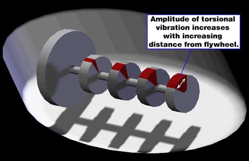
Re: harmonic balencer
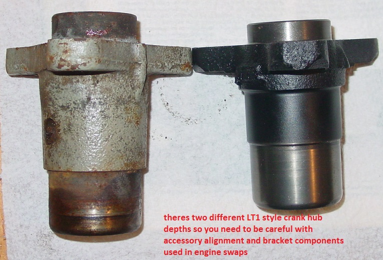
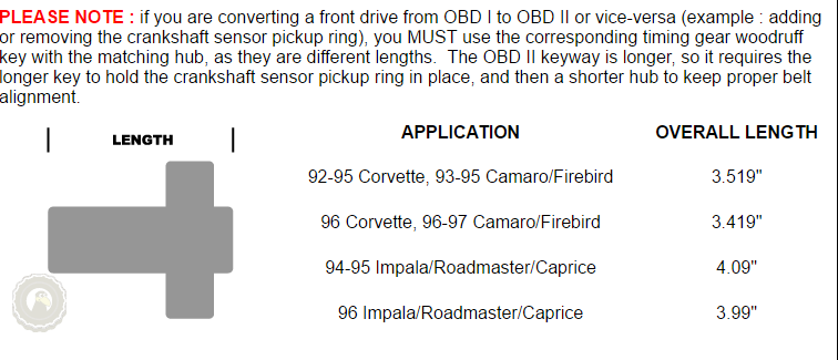
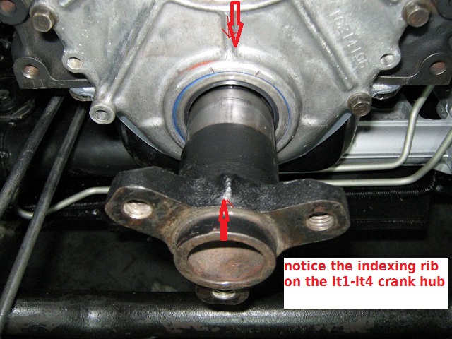
https://www.nookandtranny.com/Info_LT1.html
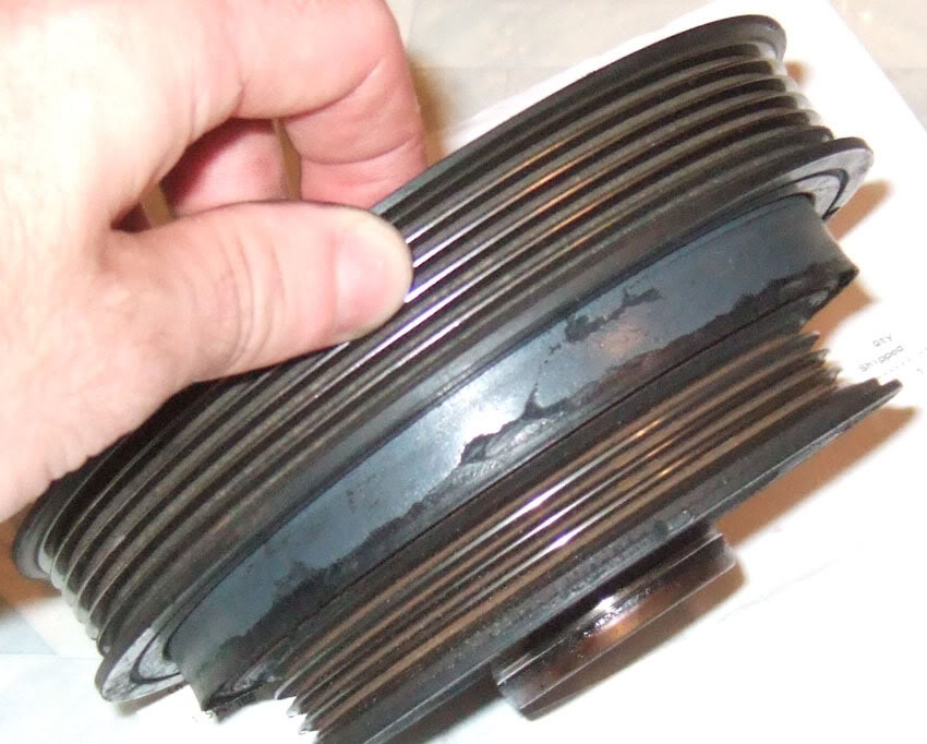
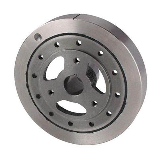
If your going to re-use it ,Id suggest having a machine shop inspect it for deterioration, of its elastomer ring and the machine shop will need to check it for cracks,and a loose or defective rubber ring binding the inner and outer hubs, provided its only going to be used on an engine used for daily transportation.
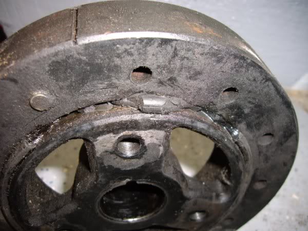
theres hundreds of thousands of old O.E.M. balancer's being used on street car engines and failures are not that common in street use, but once you start running the engines up above about 5000rpms the stress increases and that ring tends to over time degrade and fail,
chances are good that the elastomer is worn or starting to deteriorate after 30 years,
WATCH VIDEO
viewtopic.php?f=52&t=966
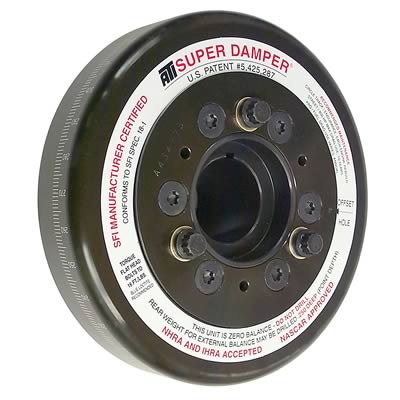
http://www.jegs.com/p/ATI/ATI-Super-Dam ... 7/10002/-1
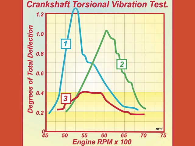
MOST NASCAR TEAMS USE ATI DAMPERS AND THEY CERTAINLY HAVE THE TEST DATA TO SUPPORT THE CHOICE
https://www.hotrod.com/articles/pit-stop-repair-stripped-crank-balancer-bolt-hole-threads/
http://garage.grumpysperformance.co...op-dead-center-1-for-timing-ignition-cam.966/
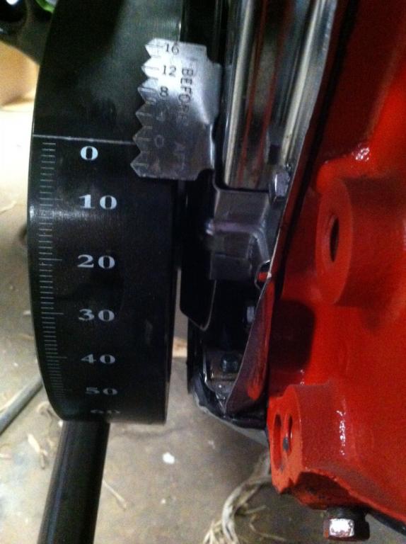
http://garage.grumpysperformance.com/index.php?threads/timing-tabs-and-indicators.1015/
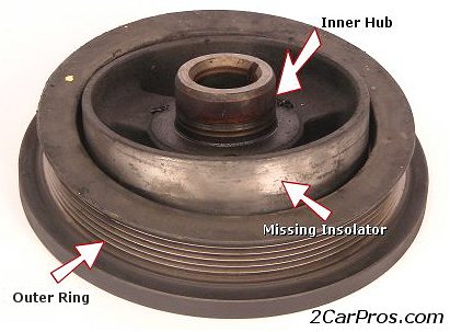
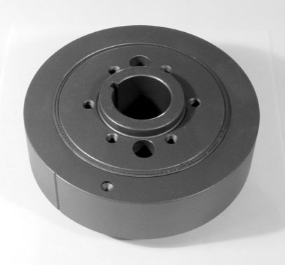
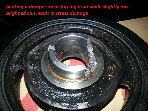
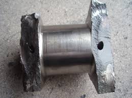
the stock TYPE balancer has a rubber ring glued between the inner hub and outer inertial ring and yes they do deteriorate over time and have been known to slip, especially if subjected to being oil soaked over time, or someone used a hammer vs the correct tool to get it back on the crank
READ THIS LINK
viewtopic.php?f=52&t=966
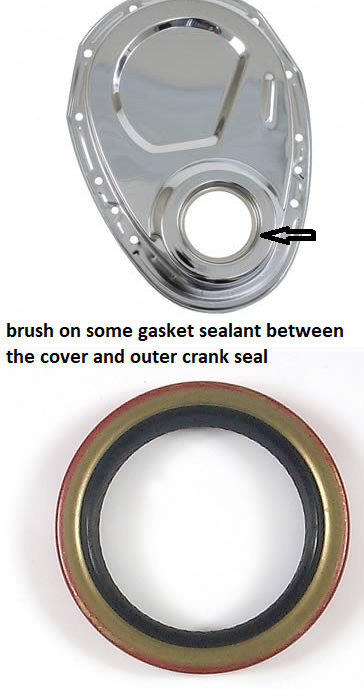
if your front crank seal leaks over time it can dissolve the elastic between the inner and outer damper hub weights
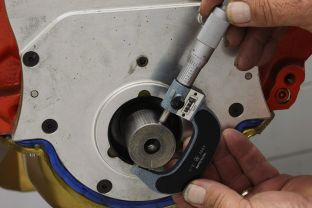
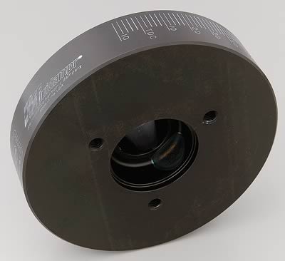
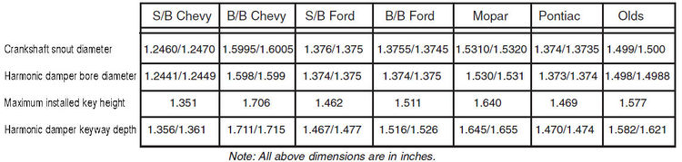
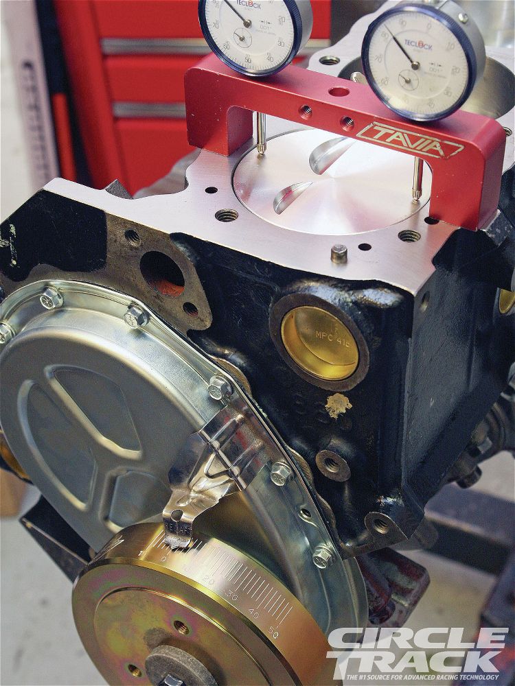
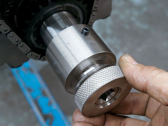
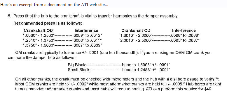
Measure the crank-snout diameter with a micrometer (above left). Ours measured 1.600 inch, which is right on spec. Then use a dial-bore gauge to determine the inside diameter of the Fluidampr damper (below). Ours came in 1.599-inch, resulting in a .001-inch interference fit. This is the right amount of clearance to provide a good snug fit on the crankshaft, but still be able to install and remove without difficulty. Another method of measuring the damper hub ID of your is with a snap gauge (above right). After setting the gauge, the micrometer is used to to determine the final measurement. In this case, the same measurement as the dial bore gage was reached.

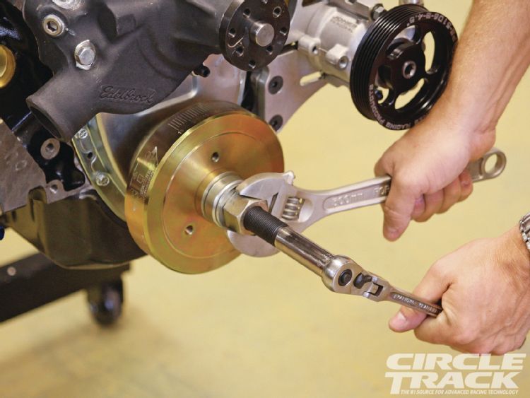
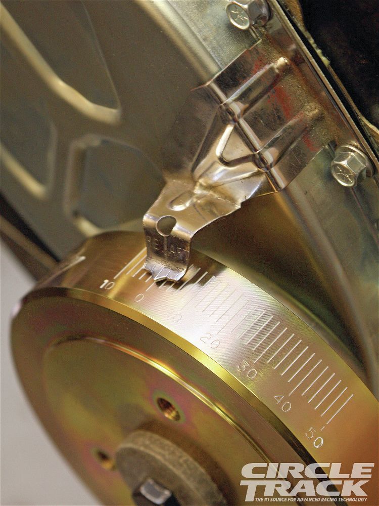
YOU can do a quick test to see if the inner and outer damper ring bond is loose,degrease the damper with some carburetor cleaner spray, then grab your wifes bottle of brite red or orange nail polish, and Draw a line on the front of the balancer across both the inner and outer hub rings, with the little paint brush under the cap, . Start the car , once it warms up reve the engine to 3500 rpm or so 6-7 times and inspect that nail polish line location, too see if the lines continue to align using the timing light. or turn off the engine and and use a brite flash lite ,If the lines are not,still lined up, the outer hub ring is slipping which misaligned the timing mark. So you end up the timing well out of speck and who knows where in relation to true TDC,.
Id suggest replacing your balancer immediately if its outer ring is loose with an SFI certified damper matching your application.
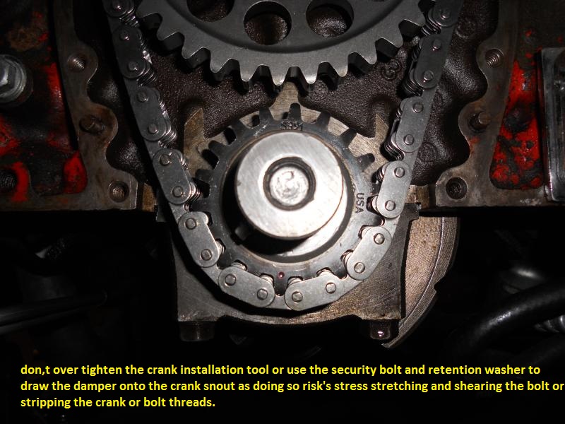
there is supposed to be about a .0001 -.0002 INTERFERENCE fit! so the damper has far less tendency to spin on the crank snout or work the woodriff key loose, you can generally polish the crank snout, and internal damper hole with a flap wheel and 400 grit sand paper enough to get a smoother surface, then, place the damper in boiling water to heat and expand it and oil its mating surface, use the correct damper installation tool, pick the damper up with oven mitts so you don,t get burned, use the tool to install it
http://www.atiracing.com/products/dampe ... ctions.htm
read these threads and links
these links should help
http://garage.grumpysperformance.com/index.php?threads/finding-top-dead-center.967/
http://garage.grumpysperformance.com/index.php?threads/damper-tool.223/#post-260
http://garage.grumpysperformance.com/index.php?threads/timing-tabs-and-indicators.1015/
http://garage.grumpysperformance.co...evy-damper-is-designed-for-your-engine.11561/
http://garage.grumpysperformance.com/index.php?threads/balance-damper-question.10462/
http://garage.grumpysperformance.com/index.php?threads/harmonic-balancer.3554/#post-26563
viewtopic.php?f=50&t=223&p=8024&hilit=damper+tool#p8024
viewtopic.php?f=53&t=3554&p=13385&hilit=damper+tool#p13385
http://www.epi-eng.com/piston_engine_technology/torsional_excitation_from_piston_engines.htm
http://www.epi-eng.com/piston_engine_technology/crankshaft_torsional_absorbers.htm
http://www.autozone.com/autozone/repair ... 52800a7dbe
http://www.go-fast.org/z28/damper.html
http://www.youtube.com/watch?v=Ex_yJ_V5 ... re=related
http://www.youtube.com/watch?v=R9LNht9E ... ure=relmfu
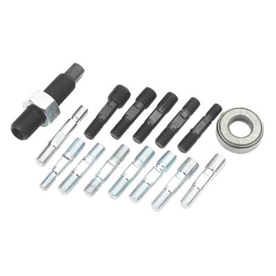
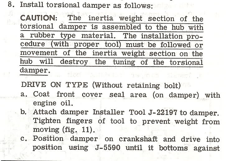
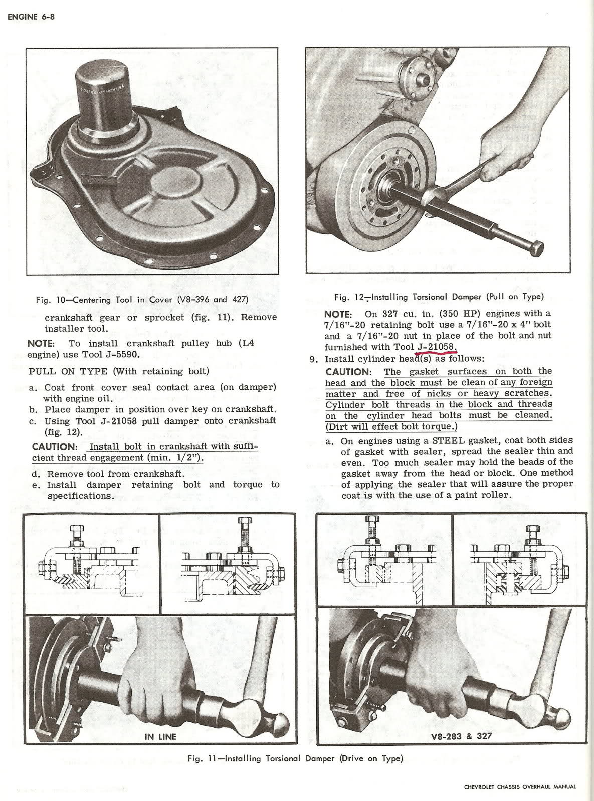
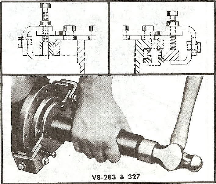
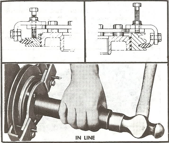
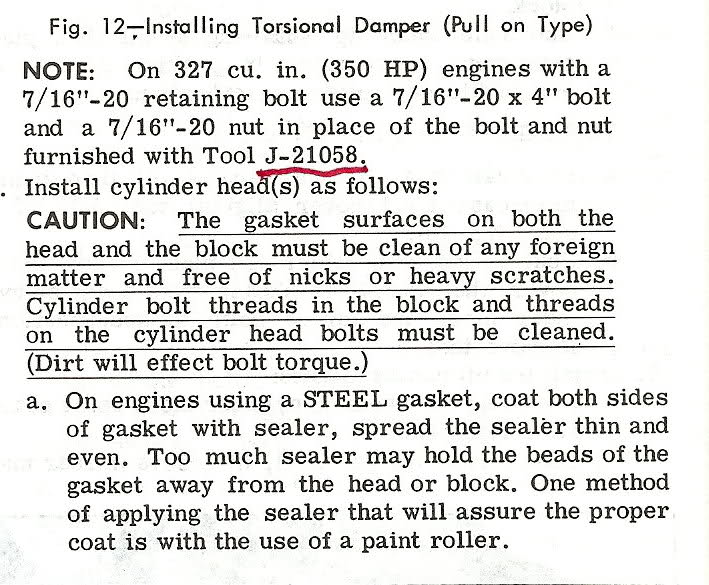
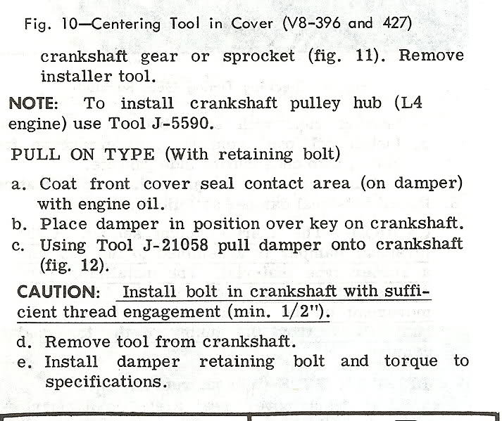
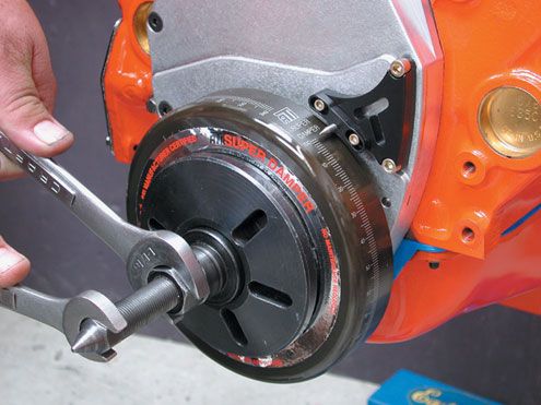
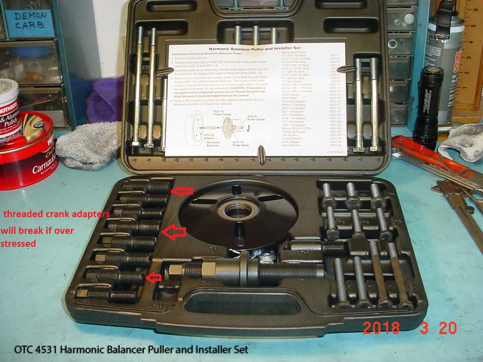
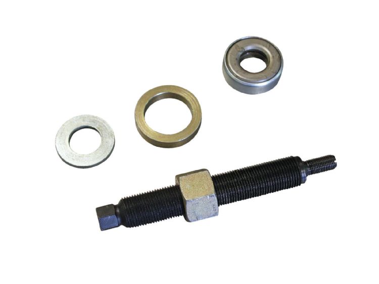
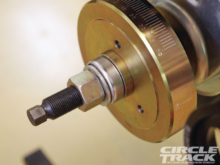
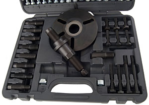
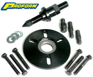
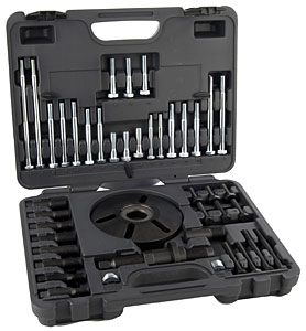
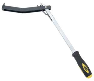
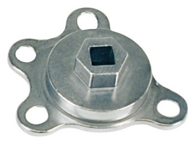
use the correct tool to install the balancer
http://www.summitracing.com/parts/OTC-6505/?rtype=10
watch video
READ THIS THREAD
viewtopic.php?f=53&t=562&hilit=+damper
KEEP IN MIND
a replacement O.E.M. style balancer will cost less than $55-$65
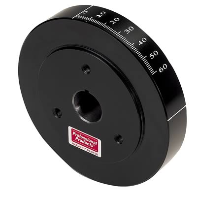
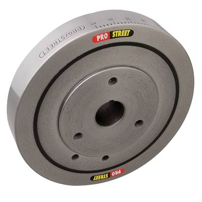
http://www.summitracing.com/parts/PFS-80000/ (AVOID THIS)
http://www.summitracing.com/parts/SUM-161358/?rtype=10
GOOD
http://www.summitracing.com/parts/FLU-650201/
now if your going to spin that engine up in the 6000rpm or greater range on occasion it may be a good idea to replace it with a SFI certified balancer, which is REQUIRED to run your car in many classes at most tracks
an S.F.I. balancer will cost a good deal more but its also far less likely to explode on hard high rpm shifts
and while Id strongly suggest their use on a high rpm race engine ID buy the S.F.I flywheel, clutch assembly, and a blow proof lake-wood bell housing before a balancer,, simply due to the fact that your less likely to loose your feet if a balancer comes apart at high rpms than if a clutch or flywheel shatters and large shrapnel chunks comes up thru your dash board
(very good)
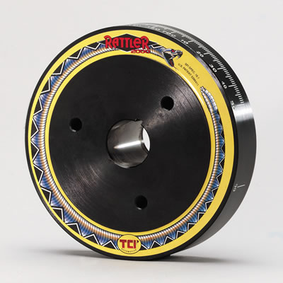
http://www.summitracing.com/parts/TCI-870001/
http://www.summitracing.com/parts/TFS-19000/
(best)
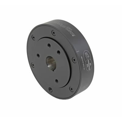
http://www.summitracing.com/parts/ATI-917060/
http://www.4secondsflat.com/Thrust_bearing_failures.html
Crankshaft Thrust Bearing Failure - Causes & Remedies
For years both transmission and engine rebuilders have struggled at times to determine the cause of crankshaft thrust bearing failures. In most instances,
all of the facts concerning the situation are not revealed at the onset of the failure. This has led to each party blaming the other for the failure based only on hearsay or what some "expert" has termed the "cause". Some of those explanations have led to an argument, that ends up in litigation while the truth lingers uncovered in the background. This document is a group effort of combined information compiled by the Automotive Transmission Rebuilders Association (ATRA), the Automotive Engine Rebuilders Association (AERA), the Production Engine Rebuliders Association (PERA), the Automotive Service Association (ASA) and bearing manufacturers. This group of industry experts has assembled the following information to consider and offers solutions that may prevent a similar thrust bearing failure.
Background:
Although thrust bearings run on a thin film of oil, just like radial journal (connecting rod and main) bearings, they cannot support nearly as much load. While radial bearings can carry loads measured in thousandsof pounds per square inch of projected bearing area, thrust bearings can only support loads of a few hundred pounds per square inch. Radial journal bearings develop their higher load capacity from the way the curved surfaces of the bearing and journal meet to form a wedge. Shaft rotation pulls oil into this wedge shaped area of the clearance space to create an oil film which actually supports the shaft. Thrust bearings typically consist of two flat mating surfaces with no natural wedge shape in the clearance space to promote the formation of an oil film to supportthe load.
Conventional thrust bearings are made by incorporating flanges, at the ends of a radial journal bearing. This provides ease in assembly and has been used successfully for many years. Either
teardrop or
through grooves on the flange, face andwedge shaped ramps at each parting line allow oil to enter between the shaft and bearing surfaces. However, the surface of the shaft, as well as the vast majority of bearing surfaces, are flat. This
flatness makes it more difficult to create and maintain an oil film
. As an example; if two gauge blocks have a thin film of oil on them, and are pressed together with a twisting action, the blocks will stick together. This is similar to what happens when a thrust load is applied to the end of a crankshaft and oil squeezes out from between the shaft and bearing surfaces. If that load is excessive, the oil film collapses and the surfaces want to stick together resulting in a wiping action and bearing failure. For this reason, many heavy-duty diesel engines use separate thrust washers with a contoured face to enable them to support higher thrust loads. These thrust washers either have multiple tapered ramps and relatively small flat pads, or they have curved surfaces that follow a sine-wave contour around their circumference.
Recent developments:
In the past few years some new automotive engine designs include the use of contoured thrust bearings to enable them to carry higher thrust loads imposed by some of the newer automatic transmissions. Because it’s not practical to incorporate contoured faces on one piece flanged thrust bearings, these new engine designs use either separate thrust washers or a flanged bearing whichis a three piece assembly.
Cause of failure:
Aside from the obvious causes, such as dirt contamination and misassembly, there are only three common factors which generally cause thrust bearing failures. They are:
- Poor crankshaft surface finish
Surface finish:
Crankshaft thrust faces are difficult to grind because they are done using the side of the grinding wheel. Grinding marks left on the crankshaft face produce a visual swirl or sunburst pattern with scratches - sometimes crisscrossing - one another in a cross-hatch pattern similar to hone marks on a cylinder wall. If these grinding marks are not
completely removed by polishing, they will remove the oil film from the surface of the thrust bearing much like multiple windshield wiper blades. A properly finished crankshaft thrust face should only have very fine polishing marks that go around the thrust surface in a circumferential pattern.
Alignment:
The grinding wheel side face must be dressed periodically to provide a clean, sharp cutting surface. A grinding wheel that does not cut cleanly may create hot spots on the work piece leading to a wavy, out-of-flat surface. The side of the wheel must also be dressed at exactly 90° to its outside diameter, to produce a thrust face that is square to the axis of the main bearing journal. The crankshaft grinding wheel must be fed into the thrust face very slowly and also allowed to "spark out" completely. The machinist should be very careful to only remove minimal stock for a "clean-up" of the crankshaft surface.
In most instances a remanufactured crankshaft does not require grinding of the thrust face(s), so the grinding wheel will not even contact them. Oversize thrust bearings do exist. Some main bearing sets are supplied
only with an additional thickness thrust bearing. In most of those instances, additional stock removal from the crankshaft thrust face surface may be required. Crankshaft end float should be calculated and determined before grinding additional material from the thrust face.
Crankshaft grinding wheels are not specifically designed for use of the wheel side for metal removal. Grinding crankshaft thrust faces requires detailed attention during the procedure and repeated wheel dressings may be required. Maintaining sufficient coolant between the grinding wheel and thrust surface must be attained to prevent stone loading and "burn" spots on the thrust surface. All thrust surface grinding should end in a complete "spark out" before the grinding wheel is moved away from the area being ground. Following the above procedures with care should also maintain a thrust surface that is 90° to the crankshaft centerline.
When assembling thrust bearings:
- Tighten main cap bolts to approximately 10 to 15 ft.lb. to seat bearings, then loosen.
- Tap main cap toward rear of engine with a soft faced hammer.
- Tighten main cap bolts, finger tight.
- Using a bar, force the crankshaft as far forward in the block as possible to align the bearing rear thrust faces.
- While holding shaft in forward position, tighten main cap bolts to 10 to 15 ft.lbs.
- Complete tightening main cap bolts to specifications in 2 or 3 equal steps.
The above procedure should align the bearing thrust faces with the crankshaft to maximize the amount of bearing area in contact for load carrying.
Loading:
A number of factors may contribute to wear and overloading of a thrust bearing, such as:
1. Poor crankshaft surface finish.
2. Poor crankshaft surface geometry.
3. External overloading due to.
a) Excessive Torque converter pressure.
b) Improper throw out bearing adjustment.
c) Riding the clutch pedal.
d) Excessive rearward crankshaft load pressure due to a malfunctioning front mounted accessory drive.
Note: There are other, commonly-thought issues such as torque converter ballooning, the wrong flexplate bolts, the wrong torque converter, the pump gears being installed backward or the torque converter not installed completely. Although all of these problems will cause undo force on the crankshaft thrust surface, it will also cause the same undo force on the pump gears since all of these problems result in the pump gear pressing on the crankshaft via the torque converter. The result is serious pump damage, in a very short period of time (within minutes or hours).
Diagnosing the problem:
By the time a thrust bearing failure becomes evident, the partshave usually been so severely damaged that there is little if any evidence of the cause. The bearing is generally worn into the steel backing which has severely worn the crankshaft thrust face as well. So how do you tell what happened? Start by looking for the most obvious internal sources.
Engine related problems:
- Is there evidence of distress anywhere else in the engine that would indicate a lubrication problem or foreign particle contamination?
- Were the correct bearing shells installed, and were they installed correctly?
- If the thrust bearing is in an end position, was the adjacent oil seal correctly installed? An incorrectly installed rope seal can cause sufficient heat to disrupt bearing lubrication.
- Examine the front thrust face on the crankshaft for surface finish and geometry. This may give an indication of the original quality of the failed face.
Once you are satisfied that all potential internal sources have been eliminated, ask about potential external sources of either over loading or misalignment.
Transmission related problems:
- Did the engine have a prior thrust bearing failure?
- What external parts were replaced?
- Were there any performance modifications made to the transmission?
- Was an additional cooler for the transmission installed?
- Was the correct flexplate used? At installation there should be a minimum of 1/16" (1/8" preferred, 3/16" maximum) clearance between the flex plate and converter to allow for converter expansion.
- Was the transmission property aligned to the engine?
- Were all dowel pins in place?
- Was the transmission-to-cooler pressure checked and found to be excessive? If the return line has very low pressure compared to the transmission-to-cooler pressure line, check for a restricted cooler or cooler lines.
- If a manual transmission was installed, was the throw out bearing properly adjusted?
- What condition was the throw out bearing in? A properly adjusted throw out bearing that is worn or overheated may indicate the operator was "Riding The Clutch".
How does the torque converter exert force on the crankshaft?
There are many theories on this subject, ranging from converter ballooning to spline lock. Most of these theories have little real bases and rely little on fact. The force on the crankshaft from the torque converter is simple. It is the same principle as a servo piston or any other hydraulic component: Pressure, multiplied by area, equals force. The pressure part is easy; it’s simply the internal torque converter pressure. The area is a little trickier. The area that is part of this equation is the difference between the area of the front half of the converter and the rear half. The oil pressure does exert a force that tries to expand the converter like a balloon (which is why converter ballooning is probably often blamed), however, it is the fact that the front of the converter has more surface area than the rear (the converter neck is open) that causes the forward force on the crankshaft. This difference in area is equal to the area consumed by the inside of the converter neck. The most common scenario is the THM 400 used behind a big-block Chevy. General Motors claims that this engine is designed to sustain a force of 210 pounds on the crank shaft. The inside diameter of the converter hub can vary from 1.5 inches up to 1.64 inches. The area of the inside of the hub can then vary from 1.77 square inches to 2.11 inches. 210 pound of force, divided by these two figures offers an internal torque converter pressure of 119 psi to 100 psi, respectively. That is to say, that depending on the inside diameter of the hub, it takes between 100 to 119 psi of internal converter pressure to achieve a forward thrust of 210 pounds. The best place to measure this pressure is the out-going cooler line at the transmission because it is the closest point to the internal converter pressure available. The pressure gauge must be "teed" in so as to allow the cooler circuit to flow. Normal cooler line pressure will range from 50 psi to 80 psi , under a load in drive.
Causes for excessive torque converter pressure:
There are two main causes for excessive torque converter pressure: restrictions in the cooler circuit and modifications or malfunctions that result in high line pressure. One step for combating restrictions in the cooler circuit is to run larger cooler lines. Another, is to install any additional cooler in parallel as opposed to in series. This will increase cooler flow considerably. An additional benefit to running the cooler in parallel is that it reduces the risk of over cooling the oil in the winter time—especially in areas where it snows. The in-parallel cooler may freeze up under very cold conditions, however, the cooler tank in the radiator will still flow freely. Modifications that can result in higher than normal converter pressure include using an overly-heavy pressure regulator spring, or excessive cross-drilling into the cooler charge circuit. Control problems such as a missing vacuum line or stuck modulator valve can also cause high pressure.
What will help thrust bearings survive? When a problem application is encountered, every effort should be made to find the cause of distress and correctit before completing repairs, or you risk a repeat failure.
A simple modification to the upper thrust bearing may be beneficial in some engines. Install the upper thrust bearing in the block to determine which thrust face is toward the rear of the engine. Using a small, fine tooth, flat file, increase the amount of chamfer to approximately .040" (1 mm) on the inside diameter edge of the bearing parting line. Carefully file at the centrally located oil groove and stroke the file at an angle toward the rear thrust face only, as shown in the illustration below. It is very important not to contact the bearing surface with the end of the file. The resulting enlarged ID chamfer will allow pressurized engine oil from the pre-existing groove to reach the loaded thrust face. This additional source of oiling will reach the loaded thrust face without passing through the bearing clearance first (direct oiling). Since there may be a load against the rear thrust face, oil flow should be restricted by that load and there should not be a noticeable loss of oil pressure. This modification is not a guaranteed "cure-all". However, the modification should help if all other conditions, such as surface finish, alignment, cleanliness and loading are within required limits.

Other External Problems. Aside from the items already mentioned, there is another external problem that should be considered. Inadequate electrical grounds have been known to exacerbate thrust surface wear. Excessive current in the vehicle drive train can damage the thrust surface. It affects the thrust bearing as though the thrust surface on the crankshaft is not finished properly finished (too rough). Excessive voltage in the drive train can be checked very easily. With the negative lead of a DVOM connected to the negative post of the vehicle battery and the positive lead on the transmission, there should be no more than .01 volts registering on the meter while the starter is turning over the engine. For an accurate test, the starter must operate for a minimum of four seconds without the engine starting. It is suggested to disable the ignition system before attempting this test. If the voltage reading observed is found to be excessive, add and/or replace negative ground straps from the engine to the vehicle frame and transmission to frame until the observed voltage is .01 volts or less. Note: Some systems may show a reading of .03volts momentarily but yet not exhibit a problem. For added assurance, it is a good idea to enhance the drive train grounding with larger battery cables or additional ground straps.
A special thank you goes out to Dennis Madden of ATRA, Dave Hagen of AERA, Ed Anderson of ASA, Roy Berndt of PERA and John Havel of AE Clevite for their contributions to this article.
The AERA Technical Committee
March 1998 - TB 1465R
viewtopic.php?f=50&t=1804&p=4633&hilit=damper+tool#p4633
viewtopic.php?f=71&t=447&hilit=lakewood
viewtopic.php?f=45&t=31&p=787&hilit=+bell+housing#p787
viewtopic.php?f=53&t=279&p=1684&hilit=+damper#p1684
posting.php?mode=edit&f=53&t=1042&p=1969
viewtopic.php?f=53&t=562&hilit=+damper