You are using an out of date browser. It may not display this or other websites correctly.
You should upgrade or use an alternative browser.
You should upgrade or use an alternative browser.
Have You Used The Wago 221 Connectors ?
- Thread starter Indycars
- Start date
I've custom wired several shops (mine included) and all passed inspection ,
with comments on high quality those locks look superior to wire nuts,
but I prefer solder connections and screws through soldered ring ends
and everything in conduit
http://garage.grumpysperformance.co...urrent-flow-grounds-and-more.3504/#post-93719
http://garage.grumpysperformance.com/index.php?threads/how-to-wire-a-shop.5/
http://garage.grumpysperformance.com/index.php?threads/tips-on-shop-lighting.16451/
http://garage.grumpysperformance.com/index.php?threads/shop-lighting.1408/
http://garage.grumpysperformance.co...ans-some-build-info-experiances.116/#post-265
http://garage.grumpysperformance.com/index.php?threads/soaked-electrical-outlet.14039/
http://garage.grumpysperformance.co...geous-mark-up-on-some-parts.16179/#post-97657
I've always suggested you have no more than TWO outlets per electrical
panel breaker
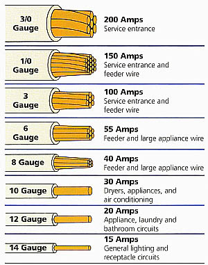
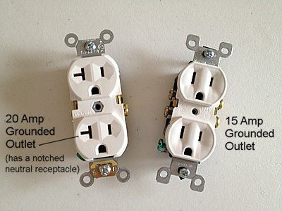
and use 20 amp outlets and use 10 ga copper wire

http://www.floridabuilding.org/fbc/...rants/grant_r98-6/2environmental/chapter5.pdf
http://garage.grumpysperformance.com/index.php?threads/how-to-wire-a-shop.5/
solder and ring end connectors, on wire ends in conduit and grounded metal boxes are the preferred route in wiring a shop
Id suggest nothing less than 10 ga copper wire
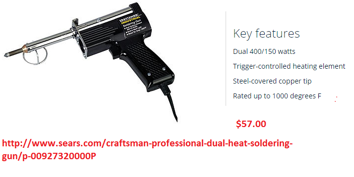
http://www.sears.com/craftsman-professional-dual-heat-soldering-gun/p-00927320000P
BETTER SOLDER GUN
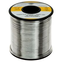
good 60/40 lead/tin solder
http://www.bing.com/shopping/4-oz-40-60 ... ux&FORM=EG
http://www.radioshack.com/product/index ... d=12582872
READ THRU THIS LINK
http://www.aaroncake.net/electronics/solder.htm
the process is rather easy and simple top do with practice, assuming the standard 14ga-12 ga under dash wiring ,you simple strip off about 1.25" of insulation on each end of the two wires, larger ga wire will require a longer section, of insulation be removed, once thats done you spin the stranded wire end between your fingers
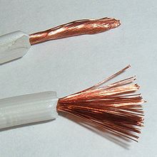
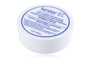
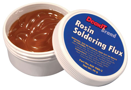
to twist it tightly so it won,t leave exposed copper wire ends and then slide on a 2.5" to 3" long section of heat shrink tube , (don,t forget to do this) now dip both the twisted copper wire ends in the flux, then twist them both together tightly in a spiral so they won,t easily separate, now add a dab of flux because much of its most likely been removed during the twist process but if you don,t do it before you twist its not going to get full coverage on the strands.
ok ideally you,ll have decent access and have the shrink tube slid on the lower wire so it won,t slide down while you solder, use the tip of the heated solder gun on the far side of the two twisted wires and touch the solder to the near side as it heats allowing the fluxed surface to draw the solder once its liquid over and around the spliced copper wire surface, once its well coated pull the solder and solder gun away , it the surface is well coated and smooth silver in appearance you can let it cool a bit then slide on the heat shrink tube , center it over the spice and use the heat from the tip of the solder gun placed near too ,but never touching, and while smoothly moving the guns tip so as not to over heat or burn the shrink tube until it firmly shrinks and hugs the spliced and soldered copper wire, making the soldered splice at least semi protected, the shrink tube, acts as insulation and a corrosion protective barrier , BTW a bit of BEES WAX can be heated and melted over the ends of the shrink tube where it joins the original insulation and used as a increased effective,moisture barrier.
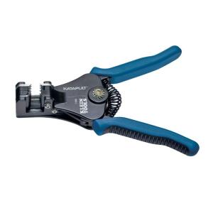
http://www.homedepot.com/s/wire+stripper?NCNI-5
http://www.homedepot.com/p/Ideal-Stripm ... 819657-_-N
http://www.alliedelec.com/search/produc ... U=70222843
http://www.sears.com/craftsman-professional-dual-heat-soldering-gun/p-00927320000P
this wiring stuffs not hard to do, but use the correct gauge wire and the correct plugs and sockets for the application and ID strongly suggest using a MINIMUM of 10ga wire for 120volt and 3/4" metallic conduit (use the correct single breaker rating for the application on the 120 volt)
120 v outlet end
black/power to the gold screw
white/neutral to the silver screw
green/ground to the green screw
120v at the box
black/power to breaker
white/ neutral to neutral bar
green/ ground to ground bar
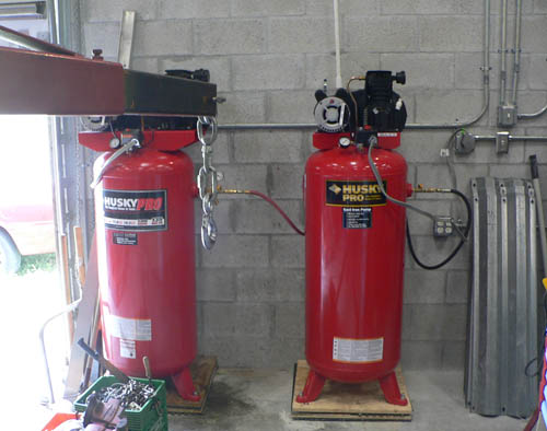
and 6GA-4 GA on the high amp 230 volt applications,like WELDERS, little 230volt stuff like compressors and lifts get along fine with (3 or 4) 10 ga wires (use the correct dual breaker rating for the application on the 220 volt)
220v at the outlet
red feed to one hot
black feed to one hot
green to ground on plug
(optional but HIGHLY RECOMMENDED)
second green to the conduit ground screw
220v at the box
red to one side of DUAL breaker
black to one side of DUAL breaker
green/ ground to ground bar
optional green/ ground to ground bar
Paste the link above in a new tab, and there is an illustration.
This will help you figure out how to attach them to the panel. Each outlet is different based on ampacity. I think there is a 30A 220 shown
This is for a 220V receptacle without a neutral path (Two prong with ground)
The red and black are power wires that attach to the terminals marked either x or y individually
for example:
Black wire = x (Brass screw)
Red wire = y (Brass screw)
bare / green = G (green screw)
This is for a 220V receptacle with a neutral path (Three prong with ground)
The red and black are power wires that attach to the terminals marked either x or y individually
for example:
Black wire = x (Brass screw)
Red wire = y (Brass screw)
White wire = W or N (Silver screw)
bare / green = G (green screw)
A QUICK NOTE ON WIRE GAUGE: 10 gauge wire is heavier than 12 gauge wire, 8 gauge is heavier than 10 gauge and so on
How 220v works with 4 wires: (one wire to each)
1 Black wire carries 120v
1 Red wire carries 120v
1 White wire acts as a common
1 Green wire acts as a ground
How 220v works with a 3 wires:
1 Black wire carries 120v
1 Red/White wire carries 110v (if you use white flag it with red electrical tape)
1 Green wire acts as a ground/common
with comments on high quality those locks look superior to wire nuts,
but I prefer solder connections and screws through soldered ring ends
and everything in conduit
http://garage.grumpysperformance.co...urrent-flow-grounds-and-more.3504/#post-93719
http://garage.grumpysperformance.com/index.php?threads/how-to-wire-a-shop.5/
http://garage.grumpysperformance.com/index.php?threads/tips-on-shop-lighting.16451/
http://garage.grumpysperformance.com/index.php?threads/shop-lighting.1408/
http://garage.grumpysperformance.co...ans-some-build-info-experiances.116/#post-265
http://garage.grumpysperformance.com/index.php?threads/soaked-electrical-outlet.14039/
http://garage.grumpysperformance.co...geous-mark-up-on-some-parts.16179/#post-97657
I've always suggested you have no more than TWO outlets per electrical
panel breaker
and use 20 amp outlets and use 10 ga copper wire
http://www.floridabuilding.org/fbc/...rants/grant_r98-6/2environmental/chapter5.pdf
http://garage.grumpysperformance.com/index.php?threads/how-to-wire-a-shop.5/
solder and ring end connectors, on wire ends in conduit and grounded metal boxes are the preferred route in wiring a shop
Id suggest nothing less than 10 ga copper wire
http://www.sears.com/craftsman-professional-dual-heat-soldering-gun/p-00927320000P
BETTER SOLDER GUN
good 60/40 lead/tin solder
http://www.bing.com/shopping/4-oz-40-60 ... ux&FORM=EG
http://www.radioshack.com/product/index ... d=12582872
READ THRU THIS LINK
http://www.aaroncake.net/electronics/solder.htm
the process is rather easy and simple top do with practice, assuming the standard 14ga-12 ga under dash wiring ,you simple strip off about 1.25" of insulation on each end of the two wires, larger ga wire will require a longer section, of insulation be removed, once thats done you spin the stranded wire end between your fingers
to twist it tightly so it won,t leave exposed copper wire ends and then slide on a 2.5" to 3" long section of heat shrink tube , (don,t forget to do this) now dip both the twisted copper wire ends in the flux, then twist them both together tightly in a spiral so they won,t easily separate, now add a dab of flux because much of its most likely been removed during the twist process but if you don,t do it before you twist its not going to get full coverage on the strands.
ok ideally you,ll have decent access and have the shrink tube slid on the lower wire so it won,t slide down while you solder, use the tip of the heated solder gun on the far side of the two twisted wires and touch the solder to the near side as it heats allowing the fluxed surface to draw the solder once its liquid over and around the spliced copper wire surface, once its well coated pull the solder and solder gun away , it the surface is well coated and smooth silver in appearance you can let it cool a bit then slide on the heat shrink tube , center it over the spice and use the heat from the tip of the solder gun placed near too ,but never touching, and while smoothly moving the guns tip so as not to over heat or burn the shrink tube until it firmly shrinks and hugs the spliced and soldered copper wire, making the soldered splice at least semi protected, the shrink tube, acts as insulation and a corrosion protective barrier , BTW a bit of BEES WAX can be heated and melted over the ends of the shrink tube where it joins the original insulation and used as a increased effective,moisture barrier.
http://www.homedepot.com/s/wire+stripper?NCNI-5
http://www.homedepot.com/p/Ideal-Stripm ... 819657-_-N
http://www.alliedelec.com/search/produc ... U=70222843
http://www.sears.com/craftsman-professional-dual-heat-soldering-gun/p-00927320000P
this wiring stuffs not hard to do, but use the correct gauge wire and the correct plugs and sockets for the application and ID strongly suggest using a MINIMUM of 10ga wire for 120volt and 3/4" metallic conduit (use the correct single breaker rating for the application on the 120 volt)
120 v outlet end
black/power to the gold screw
white/neutral to the silver screw
green/ground to the green screw
120v at the box
black/power to breaker
white/ neutral to neutral bar
green/ ground to ground bar
and 6GA-4 GA on the high amp 230 volt applications,like WELDERS, little 230volt stuff like compressors and lifts get along fine with (3 or 4) 10 ga wires (use the correct dual breaker rating for the application on the 220 volt)
220v at the outlet
red feed to one hot
black feed to one hot
green to ground on plug
(optional but HIGHLY RECOMMENDED)
second green to the conduit ground screw
220v at the box
red to one side of DUAL breaker
black to one side of DUAL breaker
green/ ground to ground bar
optional green/ ground to ground bar
Paste the link above in a new tab, and there is an illustration.
This will help you figure out how to attach them to the panel. Each outlet is different based on ampacity. I think there is a 30A 220 shown
This is for a 220V receptacle without a neutral path (Two prong with ground)
The red and black are power wires that attach to the terminals marked either x or y individually
for example:
Black wire = x (Brass screw)
Red wire = y (Brass screw)
bare / green = G (green screw)
This is for a 220V receptacle with a neutral path (Three prong with ground)
The red and black are power wires that attach to the terminals marked either x or y individually
for example:
Black wire = x (Brass screw)
Red wire = y (Brass screw)
White wire = W or N (Silver screw)
bare / green = G (green screw)
A QUICK NOTE ON WIRE GAUGE: 10 gauge wire is heavier than 12 gauge wire, 8 gauge is heavier than 10 gauge and so on
How 220v works with 4 wires: (one wire to each)
1 Black wire carries 120v
1 Red wire carries 120v
1 White wire acts as a common
1 Green wire acts as a ground
How 220v works with a 3 wires:
1 Black wire carries 120v
1 Red/White wire carries 110v (if you use white flag it with red electrical tape)
1 Green wire acts as a ground/common
Last edited:
I've used a whole bunch of that type not that brand but the same thing my friend has used them for years and finally got me to try them a couple years ago they are real good on control wiring when you are trying to find the right combo or fixing something temporary they are great