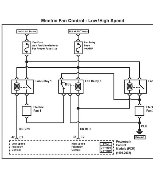
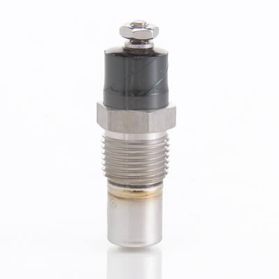
IVE got a 1996 vette, in the shop that has cooling fans that work fine if tested,individually out of the car, the three fan relays on the radiator shroud have been replaced, the sensor in the pass side heads been replaced and all the fuses and fuze links test good but the fans won,t turn on when every things connected, trouble codes indicate relays but those are newly replaced
if your reading throught this thread theres a great deal of useful related info here
http://garage.grumpysperformance.com/index.php?threads/cooling-off-that-c4-corvette.3954/
any new ideas gentlemen?
if your reading throught this thread theres a great deal of useful related info here
http://garage.grumpysperformance.com/index.php?threads/cooling-off-that-c4-corvette.3954/
any new ideas gentlemen?
Last edited by a moderator: