how altenators work

Grumpy

The Grumpy Grease Monkey mechanical engineer.
Staff member
IF YOU DON,T READ THE LINKED INFO YOU'LL MISS A GREAT DEAL


I learned decades ago to swap to a 140 amp-200 amp alternator,
as the stock 75-105 amp alternators on muscle cars and earlier corvettes are marginal at best/
if you shop carefully they can usually be found locally at some alternator re-builders for under $150
both my corvettes have 200 amp versions purchased NEW for under $250
while that may be over-kill to some I find the electric fans on the corvette and ignition and head lights work noticeably better

https://www.dbelectrical.com/alternators/automotive/chevrolet/corvette/5-7-liter/

http://www.ecklerscorvette.com/corvette-alternator-140-amp-chrome-power-master-1969-1982.html


http://garage.grumpysperformance.com/index.php?threads/chasing-a-crazy-electrical-glitch.986/

https://alternatorparts.com/cs144-series-high-output-alternators.html

viewtopic.php?f=36&t=3222&p=8575&hilit=alternator#p8575

http://www.alternatorparts.com/understa ... nators.htm

http://knol.google.com/k/how-to-tell-if ... or-is-bad#

http://autorepair.about.com/od/glossary ... rnator.htm

http://www.madelectrical.com/electrical ... sing.shtml

http://www.madelectrical.com/electrical ... wire.shtml

http://autoparts.lifetips.com/cat/61686 ... index.html

viewtopic.php?f=36&t=1169

http://www.powermastermotorsports.com/charge_wires.html

http://www.powermastermotorsports.com/g ... model.html

http://www.madelectrical.com/electrical ... sing.shtml

http://www.alternatorparts.com/CS-144_Special_offer.htm

http://www.madelectrical.com/electrical ... remy.shtml

http://auto.howstuffworks.com/alternator.htm/printable

http://www.misterfixit.com/alterntr.htm

http://www.powerbase-auto.co.uk/alternators.htm

http://www.nationaltbucketalliance.com/ ... rnator.asp

http://www.youtube.com/watch?v=w5TkStVW ... re=related


https://www.summitracing.com/parts/pwm-67293/overview/make/chevrolet/model/corvette

https://www.summitracing.com/parts/pwm-37293-114/overview/make/chevrolet/model/corvette

http://garage.grumpysperformance.com/index.php?threads/how-altenators-work.355/


https://alternatorparts.com/cs144-series-high-output-alternators.html


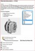
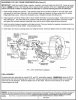
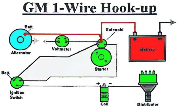
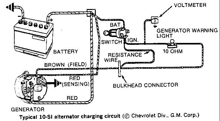
The excitor wire on # 1 terminal of the alternator starts the alternator charging on a 10 or 12si.
AlternatorWiringOverview-1973to1985Buick.jpg

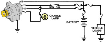
If it's a cs130, the "L" terminal is connected to the indicator lamp.

heres a 200 amp alt for the 88-91 vettes

http://cgi.ebay.com/ebaymotors/ws/eBayI ... %26otn%3D4

http://stores.ebay.com/Motor-City-Reman ... ation.html
gm1.jpg

gm2.jpg

altcharge.jpg


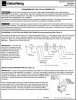
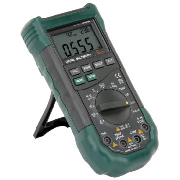
Disconnecting the battery while the engine is running isn’t a valid test for alternator function and may damage sensitive electronic parts. Instead, use a common voltmeter and the following test procedure. Although some of the steps reference typical GM alternators, the basic methodology is valid for any charging system.


01
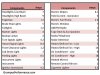
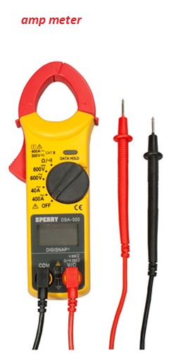
Test voltage across the battery terminals with the engine running. A good alternator should maintain battery voltage between 13.9 and 14.8 volts (14.2 is optimum). Even worst-case, with all accessories turned on, there should be at least 13 volts at the battery. Be sure that the engine is running at a high enough rpm for the charging system to function (especially if running a one-wire alternator excited at a specific rpm). If voltage is low, go to Step 02. If voltage is over 15 volts, go to Step 05.


02
Connect the voltmeter between the alternator’s output (BAT) terminal and Ground. If voltage is 13.6–14.6 volts, the alternator is OK, but power isn’t getting to the battery. Go to Step 03. If voltage is under 13.6 volts, go to Step 04.


03
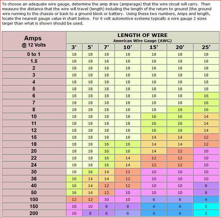
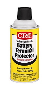
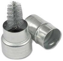
Check the battery cables and alternator charge-wire for bad connections, improper cable and wire size, or corrosion. Repair or replace as needed. Recheck as per Step 02. If voltage is a constant 13.6–14.6, the problem is solved. If voltage is normal, but slowly decreases, go to Step 04.


04
Check the alternator drive-belt. Adjust its tension or replace as needed. On a street car, the crank pulley should be three times larger than the alternator pulley; fix as needed. If voltage is normal but slowly decreases after these repairs, your alternator is OK but can’t keep up with the vehicle’s current demands; upgrade to a higher-output alternator. If you get an immediate under-13.6 volt reading, go to Step 05.


05
Test the voltage regulator. For external regulators, go to Step 06. For internal regulators, go to Step 07.


06
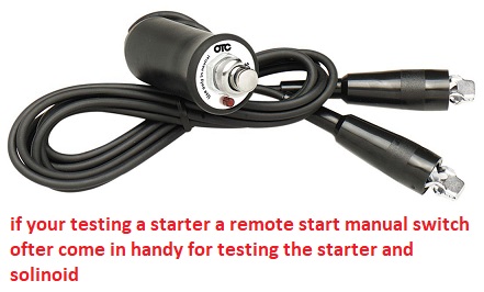
Unplug the harness from the regulator. With the engine running, connect a jumper wire from the connector’s B+ Terminal to the connector’s Field terminal (on most GM cars, that’s respectively the red and blue wires). Only do this for 30 seconds at a time. The engine will bog down. The alternator should have an audible whir and ramp up to max output. If you see a visible arc, repair or replace the regulator. If there’s no arc, the alternator has an open Field circuit or worn-out brushes. Fix or replace as needed.


07
GM SI alternator internal regulators can be checked as shown in the photo. If voltage goes up during this check, repair or replace the internal regulator. If voltage is lower than before, repair or replace the entire alternator. Late-model GM CS alternators don’t have serviceable regulators; the entire unit must be replaced.
 
Last edited:
IM always amazed at the lack of research many guys do before purchasing components, who then are stunned ans amazed to find that those components won,t work correctly without further upgrades to the electrical system, and can,t figure out why the battery drains .
example
you decide you need a 800 watt sound system and your installing it in your car when the tech suggests you might want to install a larger more powerful alternator.......IS he correct? do you need one?

http://www.zena.net/htdocs/alternators/AutoSound.shtml

http://caraudiomag.com/articles/basics-charging-systems


http://www.crutchfield.com/S-UAZgEGOb9Z ... tml?page=5

Converting Watts to Amps

http://www.powerstream.com/Amps-Watts.htm

The conversion of Watts to Amps is governed by the equation Amps = Watts/Volts

For example 12 watts/12 volts = 1 amp

so 800 watts/12 volts =67 amps


now its a sure bet that the stock alternator that puts out about 90-110 amps (depends on year) and that the basic electrical system requires almost that current flow to function,without the additional equipment additions,will require an upgrade!
so yes! only an optimist would even think, for an instant that the stock alternator would keep up with the increased current draw, of that 800 amp sound system, the tech guys who are bound to suggest a larger alternator be installed are correct, you'll want to install a 200 amp alternator like the one linked to above in this thread
the high output alternator will require a larger gauge cable between the alternator power out and the battery positive terminal and adding an additional larger gauge ground to the engine/frame/battery negative sure won,t hurt

WireGaugeToAmpTable01.jpg

clean the cable connection to battery terminals area carefully
use of a battery post cleaning brush tool is usually helpful


80078.jpg

use of this common anti-seize paste on the connecting thread surfaces noticeably reduces corrosion and helps electrical conductivity

http://www.harborfreight.com/battery...ner-94450.html
NWMDC


http://www.napaonline.com/Catalog/Ca...940_0212865359

coat the cable connections with the proper anti corrosive paste

http://s7d9.scene7.com/is/image/GenuinePartsCompany/NWMDC?$Product=GenuinePartsCompany/55709

http://www.madelectrical.com/electrical ... wire.shtml

http://www.madelectrical.com/catalog/1-0.shtml

http://www.nationsautoelectric.com/highoutput.html

http://www.nationsautoelectric.com/gmcs144.html

http://www.startersalternators.com/prod ... 8273_d_200
 
Last edited:

Attachments

  • AC_DelcoWebsite.JPG
    AC_DelcoWebsite.JPG
    33.3 KB · Views: 59
  • CS144-REASSEMBLY-INSTRUCTIONS-2.jpg
    CS144-REASSEMBLY-INSTRUCTIONS-2.jpg
    110.6 KB · Views: 59
  • CS144-REASSEMBLY-INSTRUCTIONS-1.jpg
    CS144-REASSEMBLY-INSTRUCTIONS-1.jpg
    125.4 KB · Views: 59
  • CS144-REASSEMBLY-INSTRUCTIONS.pdf
    162.5 KB · Views: 1
  • TypicalLoads.JPG
    TypicalLoads.JPG
    45.8 KB · Views: 59
THANKS ONCE AGAIN FOR AN INTERESTING POST!

BTW
Ive posted this before,
but Ive seen several cars that had markedly improved ignition and electric cooling fan operation improvements once the stock 105 amp alternators were upgraded by a swap to a 200 amp unit
the stock alternator should be sufficient but the increased amps or current seems to be of some benefit on many cars, in fact Ive seed a couple cars that ran so much better the owners seemed to think it cured long standing minor issues like slow operation of power windows and easily fouling spark plugs, which might have been more related to a weak battery, or marginal electrical wiring connections


http://www.dbelectrical.com/c-4912-high-output.aspx

http://garage.grumpysperformance.co...that-some-guys-don-t-look-at-the-clues.11176/
 
Last edited:
I frequently get questions about why cars, most of us own that are used mostly as weekend toys and not as daily transportation,cars that sit for a few days between use seem to be plagued with battery's that won,t stay charged, well Ive gone over this a few times so heres a few links of related info


http://garage.grumpysperformance.com/index.php?threads/testing-an-alternator.3222/#post-46703

viewtopic.php?f=36&t=8493&p=37179&hilit=battery+drain#p37179

viewtopic.php?f=48&t=10003&p=38749&hilit=battery+drain#p38749

viewtopic.php?f=70&t=6857&p=22377&hilit=battery+drain#p22377

viewtopic.php?f=70&t=2133&p=19303&hilit=battery+drain#p19303

viewtopic.php?f=48&t=5144&p=14905&hilit=battery+drain#p14905

viewtopic.php?f=44&t=3401&p=8972&hilit=test+alternator#p8972
 
Last edited by a moderator:
ANDY said:
Looking for a little advice... Have been enjoying a "new to me" 1961 Corvette for a few weeks. A transmission shop left the key turned on and killed the battery. Had to jump it a few times, and then it just quit starting. No clicks, nothing.
I Took the battery in to find it was bad and replaced it.
But, still won't turn over. Clicks a few times, then quits, and then won't click again unless I wait a half hour or so.
The "dome" light appears to go in and out with this behavior too, like the whole car is losing power when it fails to start.
Could this be a bad starter or bad generator? Where would you look next? (I'm not a skilled mechanic)...
Thanks!

ampmeter.jpg

cars use DC homes use AC current ,know the difference and use the correct meters

http://www.amprobe.com/Amprobe/usen/Contests_Promotions/amp-25.htm?gclid=CJGbirzF59ACFUU2gQodJ6UIqA

http://www.powerstream.com/DC-clamp.htm

https://www.amazon.com/Amprobe-AMP-...1481301013&sr=8-9&keywords=fluke+dc+amp+meter

http://garage.grumpysperformance.com/index.php?threads/measuring-amps.15548/

http://en-us.fluke.com/training/tra...-digital-multimeter-plus-clamp-accessory.html

If your car has a hard time starting or it won,t start it may be a simple corrosion /connection issue or it may be something more complex, a few tests and visual inspection won,t hurt in determining the source, get out your multi meter and set it to D,C, VOLTS 0-20
you need to logically isolate the problems source.
a lose electrical cable , or a defective starter or a connection or ignition switch may be suspect.

image_6238.jpg

place the black common lead on the bat neg,POST NOT the CABLE .place the red lead on the bat positive,POST NOT CABLE,
it should read near 12-12.7 volts

now start or try to start the car if the voltage drops a few volts , the NEW battery may be defective,once the car starts the alternator should provide about 14 plus volts
check and clean all cable connections on the battery and car frame,
its much more likely the battery cable connections too the battery or the ground cable may be faulty,
now move both meter leads to the battery cables and repeat the test if the battery voltage drops noticeably more one or both cables are loose or defective,

http://www.wikihow.com/Clean-Battery-Corrosion-and-Build-Up
a cup of warm water with two table spoons of baking soda dissolved in it and two drops of DAWN dish washer detergent with a stiff tooth brush helps remove corrosion from terminals before you use the cleaning tools
if your dome light dims as you stated when you try to start the car, chances are very good the battery cable or ground connections need to be carefully cleaned, and re-tightened!
AFTER SPRAYING THE CLEANED SURFACES WITH THE SPRAY BELOW
btpc1.jpg

btpc2.jpg

btpc3.jpg


once the car starts it should have the alternator kick in and the meter should read near 13.9-14.7 volts at idle.
btw the most common electrically related problem I see on a consistent basis is corroded or badly rusted or defective battery connections and grounds so before you go crazy its a good idea to replace those as a first step in any electrical problem diagnoses


as always you simply isolate and test in a logical manor to find the cause, random guessing and parts replacement without testing gets damn expensive and your unlikely to randomly guess correctly before it costs you more than it should to correct! ,Id start with having a local auto parts store load test the battery after getting the multi meter out you have , and cleaning all the cable connections carefully and ohms test them
and yes you need a multi meter and if the battery checks out Id be looking at the connections on the starter and the starter itself


http://garage.grumpysperformance.com/index.php?threads/won-t-spin-or-start.11154/

http://garage.grumpysperformance.com/index.php?threads/how-altenators-work.355/

http://garage.grumpysperformance.co...k-clunk-clunk-start-problem.11422/#post-52439

http://garage.grumpysperformance.com/index.php?threads/bits-of-auto-battery-and-related-info.3901/
 
Last edited:
Interesting.

I turned headlights on. 1500 rpm. Voltage drop test negative to negative and red probe to Alt case. I got 0.36 Volts. Hmmmmmm
 
posted by
chromebumpers
quote]
When you turn the key to "on" you should have only the alt/gen and the oil lights on, nothing else. If the turn signal light comes on wires are crossed under the dash which is common on restorations. There is only 2 wires coming from the alt, one large, one small. The small wire runs up front to the headlight switch and off to the idiot light.
I would connect a temp but separate idiot light and see how that behaves.

IMG_0765.GIF


It is absolutely essential that the (D+) terminal on the alternator be connected to a functioning "Alt" warning light in the instrument cluster. If this light is missing or defective, the alternator will NOT charge the battery!

The system is very simple, but it's absolutely critical that you get it right. The (D+) terminal on the alternator MUST connect to a functioning warning light in the instrument cluster. There should be just one wire (blue) from the (D+) connector on the alternator to the button on the bottom of the normal indicator light in the dash. The dash light is also wired from the (D+) (Blue) to ignition terminal #15 on the coil, which in turn is connected to the positive (+) post on the battery (Black). There is no ground wire on the light; the body of the bulb is connected to ground via the light holder (which also provides the ground connection for the other dash lights as well.) The three bulbs (ALT/OIL/TURN) all have a common connection in the socket which goes to ignition terminal #15 on the coil (which receives power from the (+) post on the battery by way of the ignition switch).

The alternator must get a feedback current through the "Alt" lamp in the instrument cluster so it can sense the battery voltage; it uses that as part of the alternator's internal circuitry needed to charge the battery. In other words, with the ignition on but engine off, the indicator light sees 12 volts from the battery (via ignition terminal #15 on the coil) and glows, but with the engine running, it sees 2 volts (14 volts minus 12 volts) running the other way, from the alternator. It doesn't glow (needing more than 2 volts to do that), but the alternator still "sees" the connection to the battery.

So -- If the Alternator is charging, the (D+) terminal has 12 volts on it; the blue wire from (D+) carries 14 volts to the "Alt" light in the instrument cluster. When the engine is running, there is 12 volts on the *other* side of the lamp from ignition terminal #15, so potential difference is only 2 volts and the bulb doesn't light. But, if the alternator dies or the drive belt breaks, there is no voltage on (D+) (looks like ground) and current flows from #15 thru the lamp to (D+), and the "Alt" lamp comes on to warn the driver of a problem.

An LED light won't work for this purpose. LED's are diodes and will not allow current to flow in the opposite direction. With the LED, it would see the 12 volts, but the reverse flow 2 volts would be stopped by the diode nature of the LED, so that wouldn't work.

The 12-volt 2-watt indicator bulbs are available at any VW parts store. The same bulb is used for the speedometer illumination bulbs (two of them) and the other indicator bulbs in the instrument cluster. In a pinch you can borrow one of the illumination bulbs to replace a blown Alt indicator bulb -- the speedometer will be a bit dim on one side but can still be seen until you get a replacement bulb.[/quote]


Last edited:
ALTERNATOR OPERATION
by Jim Mais


MOT_ALT.GIF shows the internal wiring of the Motorola alternator with the external regulator. The principles apply to all alternators although there may be minor differences in internal wiring.

The stator is the fixed/non-rotating part. It consists of a laminated iron frame with 3 windings distributed around it. Electrically, these windings are 120 degrees apart.

The rotor is an electro-magnet which is energized by current fed thru the slip rings and brushes. As the rotor magnetic field sweeps past the stator windings, it induces an alternating current in the windings. There are actually three voltages; each winding has a voltage 120 degrees out of phase with its neighbor.

To convert the alternating current to DC to charge the battery, a full-wave bridge rectifier is used. This consists of the 6 large rectifier diodes shown in the drawing. Any time a winding has positive polarity, the diode on the right conducts, connecting it to battery. In the next half cycle, when the winding is negative polarity, the diode on the left conducts. A "full-wave" circuit means that all the windings are used all the time.

The output voltage is a combination of the waveforms from the 3 windings. This results in an output which is pretty close to DC.

When the alternator is not turning, the diodes prevent battery current from flowing back into the alternator. Thus, no cut-out relay is required as with generators.

FIELD EXCITATION To control the output voltage, and maintain the correct battery charge, the field winding current is varied. The regulator is a solid-state sensor which monitors battery voltage. When the battery voltage is low, more field current is supplied.

Excitation voltage is supplied by the alternator windings, rectified by the Trio diodes (shown as the smaller diodes on the drawing). These diodes are quite small since maximum field current is only about 2 Amps. The regulator acts as a rheostat, controlling the current from the Trio diodes to the field.

Unlike a generator, the alternator is not self-exciting at start-up. A generator has field poles made of soft iron which hold a residual magnetism. The alternator field structure has little residual and thus has almost no output unless field current is supplied.

To get the alternator going, a tiny field current must be supplied. In most designs, this current is initially provided by the dash warning light. With the Ignition switch closed, current flows thru the Lamp to the regulator and into the field winding. If the dash warning light is burned out or disconnected, the alternator probably won't begin charging.

(Note: The drawing shows an externally regulated alternator. Other designs, and internally regulated units may place the regulator either in the DF lead or in the D- lead. Operation is the same though.)

As the alternator speeds up, stator voltage increases until the Trio diode voltage is sufficient to provide field excitation. As the voltage approaches 12 Volts, the dash Lamp goes off because it has the same potential on both sides.

REGULATION How does the regulator sense the battery voltage when it's not even connected to the battery? The answer is that the voltage at D+ almost exactly follows the voltage at B+ because the voltage drop in the Trio diodes is almost the same as that in the larger rectifier diodes.

If battery voltage drops, the regulator circuitry senses that fact (at D+) and increases the current flowing into DF until battery voltage is restored. Most regulators also include some form of temperature compensation. A cold battery requires slightly higher voltage to fully charge. A temperature sensing element in the regulator increases output voltage at low temperatures.

Current limiting is not provided in alternator regulators since the alternator magnetic structure inherently limits the maximum current that can be produced.
 
Back
Top