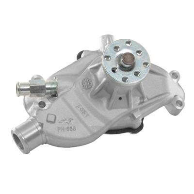
How to Replace the Waterpump and Timing Chain
a basic timing chain set like this from cloyes works great in most SBC applications
https://www.summitracing.com/parts/CLO-9-1100/
How to Replace your Waterpump & Timing Chain by Lars Grimsrud SVE Automotive Restoration Musclecar, Collector & Exotic Auto Repair & Restoration Broomfield, CO Rev. B 6-15-00 This tech paper will discuss the replacement of the waterpump and the timing chain & gears on a 1985 L98 ("regular" Chevy 350) C4 Corvette. Other years are very similar in procedure, and utilize the same overall technique. The procedure outlined here differs slightly from the Service Manual, and is based on my years of experience doing this work in the quickest, least painful, most economical way while keeping the level of quality high. It is recognized that other people will have different methods of doing things, and may disagree with specific methods and procedures that I use. Overview The waterpump and the timing chain are virtually regular maintenance items on a small block Chevy, but it can be costly to have this replacement work performed by a shop. With the proper tools and instruction, this work can be accomplished by anybody with some mechanical ability, but some words of caution are in order. First, it is important to have the proper tools. This article includes a list of tools and supplies needed to do this work. I would not recommend attempting to do this work if you do not have the proper tools: it will become an extremely frustrating experience, and you'll end up with a partially disassembled car being towed to the shop. You can buy all the tools for less than the cost of having the work done, so get set up with the right stuff before you try doing this job in a make-shift fashion. Second, be aware that this is not a particularly "fun" job. There is nothing magically difficult about it, but you're going to get dirty, you're going to sweat, you're going to be uncomfortable, and you're going to make a mess out of your garage. If this does not sound appealing to you, reconsider doing this work yourself. If you're up for the challenge and satisfaction of doing the work, then proceed! When to Replace The L98 Corvette uses an aluminum-bodied waterpump. It is a good, durable unit, and has good life expectancy providing the cooling system is properly maintained. I have seen these units fail as early as 80,000 miles, and I've seen some go past 150,000. The failure mode is usually failure of the shaft bushing and seal, causing the pump to leak out of the drain hole in the bottom of the casting. This leakage can start very subtly, with the only indication that your car will run hot, and your radiator is mysteriously a little low after a couple of days' driving. Other times you'll end up with a massive leak and a noticeable puddle of antifreeze under your car. The leak is not readily visible from the top of the engine, so you'll appear to have a mystery leak. To check, simply run your finger under the "nose" of the waterpump behind the waterpump pulley. If it comes up wet, it's time to replace. Timing chains gradually deteriorate. The force required to turn the camshaft , which in turn is connected to the distributor and the oil pump, gradually "stretches" the timing chain over time. As the chain stretches, the camshaft timing becomes retarded. This causes a loss of low-rpm throttle response and low-end torque. If the situation is allowed to go on, the chain will eventually become so slack that it will jump one or several teeth on the camgear. At best, this will cause a dramatic loss of power with backfiring up through the induction system. At worst, this will cause valve-to-piston interference, and will trash your engine. For this reason, it is best to replace your timing chain and gears as a preventative maintenance step, before the chain goes too slack. You can check the total amount of slack in your chain very easily without disassembling the engine. Since the distributor is connected directly to the camshaft, you can actually "see" the backlash in the valvetrain like this: Pop your distributor cap off. Put a socket, short extension, and a ratchet on the harmonic balancer bolt. Turn the crank just enough in one direction so that the rotor starts to move. Stop. Scratch a mark on your harmonic balancer or harmonic balancer pulley at the timing mark plate. Now slowly turn the crank the opposite direction while observing the rotor. As soon as the rotor starts to move, stop. Note how many degrees the crank has moved. This is how much slop you have in your chain. Divide the number by two, and this is how many degrees retarded your cam is running. Retarding your cam by 2 degrees will noticeably affect performance. If you're running twice that amount, you're getting pretty close to jumping a gear. Most small block Chevys will not jump the gear before 120,000 miles (but I've seen exceptions..), but will see a performance improvement by changing the chain at about 90,000. In other words, when your waterpump goes out, it's probably time to change the chain, too. The Difficult Part Right off the bat, let me tell you what the difficult part is. Chevy presses their harmonic balancers and their crankshaft timing gears onto the crank snout. They can be a bear to pull off, especially when you're working with the engine in the car. I will talk about the technique and tools needed to do this as easily as possible, but be aware that it is not a pleasant process. All other aspects of doing this work are very straight forward and relatively simple. Tools and Equipment Required As a minimum, you will need the following tools: 1. Full set of �" drive sockets, standard, with ratchet, extensions and breaker bar 2. Full set of 3/8" drive sockets, standard and metric, deep & regular, with ratchet & extensions 3. �" to 3/8" adapter so you can use your �" drive ratchet on your 3/8" drive sockets 4. Flat bladed screwdrivers of various lengths 5. Set of Torx wrenches 6. Combination wrenches:13mm, 14mm, �", 9/16", 15/16" 7. Flare nut wrench ("Lion Wrench") 5/8" 8. Regular & needle nosed pliers 9. Big hammer 10. Sharp chisel 11. Torque Wrench 12. Harmonic Balancer Puller set (See note and description on this) 13. Drain pan 14. Razor blade 15. Rags 16. Silicone sealant 17. 1 qt Power steering fluid 18. 2 gal. Antifreeze 19. Waterpump 20. Timing chain & gear set 21. Gasket set for timing chain R&R 22. Bag of kitty litter ("Floor Dri") 23. Drop light 24. Teflon Pipe Thread Tape 25. Assembly Lube (like Lubriplate or equivalent) 26. Timing light Optional, but recommended and useful, tools: A cheap �" drive socket set, like the ones you can buy from Harbor Freight, Tool King, etc. with the big "Made in Taiwan" sticker on it. I never use these sockets as "sockets." You use them as special spacers and backing rings to press things on and off and to hammer on and beat on. When you're through using them for this job, they work GREAT for pressing out A-arm bushings, Rear End bushings, alternator bearings, and anything else you can think of. You gotta' get one of these. A note regarding the Balancer Puller Set: The puller set consists of a forged, finger-shaped center plate that has a large-diameter, center bolt running through it. This center bolt typically has a tapered, swivel end-piece on it that presses against the crankshaft. The harmonic balancer is connected to the finger-shaped center plate using 3 bolts typically provided in the set. All of the sets that I have seen have a center bolt which is too long to fit onto the front of the Corvette balancer and still be able to get a wrench onto the bolt without hitting the fan/radiator. I have solved this problem by having a friend with a lathe cut my puller's center bolt down to 3.25" total length, and re-machining the tapered end that slips into the swivel end piece. Modifying your puller to this configuration will greatly ease the job, and will keep you from having to pull the fan, shroud, and radiator out of the car. It would be worth your while to do this mod, even if you had to hire someone at a machine shop to do the work for you. Procedure This procedure typically takes me about 4 hours from start to finish on a C4, but I've done it a few times. Allow yourself a day for a leisurely pace of wrenching and beer drinking. General tips: Keep your work area clean and organized. It'll make the job seem much easier. I like to lay a clean towel out on the ground by the car or on an adjacent workbench. As each bolt, screw, nut and component is removed, I lay the parts out carefully on the towel. Whenever possible, I put screws back into the holes that they came out of after the component is removed. Wipe up spills and sweep the area as you progress to keep things clean and pleasant. On a C4, it is very easy and practical to use the top of the inlet plenum as a storage area for tools and parts when working on the engine. Avoid this as much as possible: it will get oil and grease all over your plenum, and eventually, something will roll off and disappear into your engine compartment or under the car. If you want to use the plenum as a temporary "tool holder," at least put a towel over the plenum to protect it. Good work practices will make this job much less frustrating. Virtually all of the work will be performed from the passenger side of the engine compartment, so set up your tools and work area on the right side of the car. Step-by-Step: � Park the car on a level surface. � Remove the MAF with the plastic air duct connecting the Throttle Body to the Air Cleaner Housing. Be careful pulling the electrical connector off the MAF so as not to damage the wires or the connector. � Drain the engine coolant. I do this by just yanking the lower radiator hose at the radiator and removing the radiator cap. � Remove the upper radiator hose. � Before removing the serpentine belt, break loose the waterpump pulley attach bolts. The belt, being in place, will keep the pulley from turning as you break the bolts loose. Put a box wrench on the bolts and give the wrench a few sharp whacks with your hammer to break them loose. � Take a look at your serpentine belt routing. If you think that there's a possibility that you'll forget how it's routed around the various components, take a minute with a pencil and a piece of paper to make a crude sketch of the routing. It'll save you some trial and error later... � Using a �" drive ratchet inserted into the serpentine belt tensioner (located just underneath the A/C compressor), take the tension off the belt and slip the belt off the A/C compressor pulley. Release the tensioner and remove the belt. � Remove the water pump pulley. � Remove the Throttle Body Heater Hose between the TB and the Intake Manifold. � Release the pressure on the fuel system. There is a pressure port on the engine fuel rail on the passenger side of the engine towards the rear of the rail. Either put a big rag under the port to catch the fuel as you depress the Schraeder Valve and relieve pressure, or hook up an Airconditioning Charging Hose to the port and allow the fuel to flow into a can. Also, remove your gas cap: pressure in the tank caused by a warm day will cause fuel to be pushed out of the tank and to the engine. � There are two components mounted right over the front of the engine related to the A.I.R. system. These components are connected with rubber hoses attached with clamps. The component located closest to the A/C Compressor is the Air Switch Solenoid. The component located in the center front of the engine is the Air Control (Diverter) Solenoid. Loosen the hose clamp at the A.I.R. pump connecting the hose from the Air Control Solenoid. Remove the bolt attaching the Air Control Solenoid to the top of the Waterpump. Remove the vacuum hose and the electrical connector from the Air Control Solenoid. Disconnect the hoses connecting the Air Control Solenoid to the Inlet Filter Tube (lower hose) and to the Air Switch Solenoid. Now remove the Air Control Solenoid. � To remove the Air Switch Solenoid, loosen the hose clamp at the rear of the Solenoid and pull the hose off. Disconnect the electrical connector. Remove the two 10mm screws attaching the Air Switch Solenoid to the A/C Compressor Bracket. Disconnect the Air Switch Solenoid from the lower hose. Leaving the vacuum hose in place (it's retained by a locking feature that you can remove if you want to, but I just leave it), remove the Air Switch Solenoid and lay it over towards the driver's side of the engine out of the way. � Remove the electrical connector from the A/C Compressor. � Remove the 4 (10mm) screws attaching the A/C Receiver/Drier: There are two down on the frame crossover, and two on the radiator fan shroud. � Remove the nut attaching the rear A/C Compressor Strap to the forward exhaust manifold bolt. � Remove the rear, outboard A/C Compressor mounting bolt and the rear Compressor Strap. � The forward, lower A/C Compressor mounting bolt is hard to see. It is on the forward side of the compressor right below the pulley. It is usually covered in grease, and very well disguised. You cannot use a socket or a box wrench on it, because the pulley will interfere. Once you've scraped the grease away from it, you can use an open end wrench to break the bolt loose. The bolt also has a Torx provision in the head (keep scraping the grease away... you'll find it). Using a T45 Torx, remove the bolt. � Remove the two nuts securing the A/C Compressor bracket to the passenger side of the waterpump. The A.I.R. Inlet Tube & Filter can now be pulled up and removed. The entire Compressor/Bracket assembly will now be loose. � Make sure that your gas cap is removed and that pressure has been relieved on the fuel rail. Place a rag under the fuel line fittings at the fuel rail. Using your 5/8" Flare Nut Wrench, loosen and disconnect the fuel supply and fuel return lines at the rail. Be careful not to loose or damage the "O"-ring seals attached to the ends of the fuel lines. � Slide the loose Compressor/Bracket assembly forward as far as possible. You can now get to the rear upper Compressor mounting bolt. Loosen it and remove it. By wiggling and positioning the Compressor just right, there is just barely enough space to pull the bolt out the back. � Remove the Compressor from its bracket and let it hang towards the passenger side of the engine compartment. Remove the Bracket from the engine compartment (threading the fuel lines out of it) and set it aside. Put all the hardware you've removed back into the holes that it all came out of. � Remove the lower radiator hose and the one heater hose from the waterpump. � Remove the 4 waterpump bolts. You'll need a deep socket on the passenger side. Note that the two studded bolts on the passenger side are different lengths: lay them on your clean towel in such a way that you'll remember which one goes where. Remove the waterpump. � Using your 15/16" box wrench, remove the heater hose fitting from the waterpump. Clean it up with a wire wheel, apply new teflon tape to the threads, and install the old fitting into your new waterpump. If you are not replacing the timing chain, you are now ready to scrape off the waterpump sealing surfaces with a razor blade, clean all your parts and bolts up, and put things back together with your new waterpump. If you're going on to the chain, keep right on going... � Remove the 3 bolts attaching the harmonic balancer pulley to the balancer. � Remove the harmonic balancer center attach bolt. If you have a manual transmission car, put the car in gear and set the brake. This will keep the crankshaft from turning. If you have an automatic car, put your socket & ratchet on the bolt and give it a few whacks with a hammer to break it loose. � Remove the pulley. � Place an oil drain pan under the steering gear. Using your 5/8" flare nut wrench, remove the power steering fluid line from the steering gear located right in front of the harmonic balancer. This is going to leak, drip and make a mess for as long as you're working with the balancer, so be prepared to get fluid all over your hands and tools... � Before attaching your balancer puller to the harmonic balancer, grease the threads on the puller's center bolt, and grease the swivel tip's friction surfaces. Now attach your custom-length balancer puller to the harmonic balancer and come up with a combination of sockets/extensions that will allow you to get a breaker bar onto the puller tool while avoiding contact with the steering gear, crossmember, and radiator fan assembly. If you have cut your tool to the right length, you will be able to attach a �" drive socket with a breaker bar without hitting the steering gear or the crossmember. � To keep the crankshaft from turning while tightening the puller center bolt on an automatic car, jam a long screwdriver in between the bolts that attach the puller to the balancer and allow the screwdriver to get jammed up against the power steering pump pulley. With the crankshaft jammed in this fashion, tighten the puller center bolt with a 12-point socket and your breaker bar. Due to the limited space, you will most likely have to tighten the bolt 1/12th of a turn at a time, and keep repositioning the socket. Start tightening the bolt to pull the balancer off the crankshaft. You may want to place some rags over towards the driver's side of the engine compartment just in case your grip slips on the breaker bar. There are lots of sharp, hard things for you to cut and bruise your knuckles on over there if your breaker bar were to slip... This is a tedious, slow, messy process (since the steering gear fluid line is soaking your tools with dripping power steering fluid). With a bunch of grunting, sweat, and cussing the guy who wrote this stinking article, the balancer will slowly come off the crank. � Re-attach the power steering fluid line and tighten it. � Have a beer. You're gonna' need it. � Remove the 7/16" hex head bolts attaching the timing chain cover. These bolts are very close to the cover itself, and you may need to use a thin-walled, 12-point, �" drive socket to get a grip on them. � The timing chain cover has a lower lip on it. This lip is captured when the oil pan is installed (during engine assembly, the timing chain cover is installed first, and then the oil pan is installed over this lip to capture and secure the cover and the lower gasket). These engines are actually not designed to have the timing chain cover removed without first removing the oil pan. Once you have removed the timing chain cover screws, you will, therefore, have to do a little twisting, prying and wiggling to get the cover and its lip to release from the oil pan. It's okay if you bend the lip a little: it can be bent back afterwards. Just get the cover off. Wipe off the oil pan lip, and stuff a big rag into the opening to keep dirt, debris, crap and tools from being dropped into the oil pan. � The two timing gears are each identified with a timing mark in the form of a little dot. Before pulling the gears off, I like to pre-align the dots so that I know that the new gears can simply be slipped right into place without any other alignment. You can install the harmonic balancer attach bolt in the crank so you can turn the crankshaft with your ratchet. Rotate the crankshaft so that the dots are right adjacent to each other (cam gear dot straight down, crank gear dot straight up). Now, if you use your hammer to whack the ratchet on your crank bolt, you can get the bolt out of the crank without the crank actually turning. � Remove the 3 bolts attaching the cam gear to the cam. Use a hammer to whack your wrench or ratchet to keep the engine from turning over. Remove the gear and the chain. � This next technique (Method 1) has received some criticism from some "purists," but I assure you it works. There are pullers available to pull the crank gear off the crankshaft. This gear, however, is pressed on pretty freakin' hard, and I've broken pullers and knuckles in unsuccessful attempts to get these gears off. I've also seen guys who use, and recommend, a torch to heat up the gear to get it off. Personally, I would never use an open flame in an engine compartment, especially since we just disconnected the fuel lines from the fuel rail... If you have a puller, use it. If it works, that's great. If not, here's how to get the gear off: � Method 1: With the crank gear "dot" pointing straight up, the keyway is also in a near-top location. This is the weakest point on the gear. Using your sharp chisel and your big hammer, put the chisel in between the two gear teeth right above the keyway. You can do it at an angle if you need to. I have best luck working from the driver's side of the engine compartment for this operation, but I'm right handed. Now give that chisel some confident whacks with your hammer. Space is limited, so you won't be able to get any over-the-shoulder type of swings, so just keep whacking away at that chisel. Don't whack the crank snout...! After a few whacks, the hardened heat treated crank gear will crack right at the keyway, and you can slip it off the crank with your bare fingers. I've had the gears crack in as little as 4 blows. The last one I did took about 50 solid hits, and then the gear broke right in half. This will not damage the crank, and it is perfectly safe to do (as long as you don't hit your fingers). I have had 100% success with this method in 25 years of replacing small block timing chains. � Method 2: This method has been used with success, and has been submitted by, BADMUDE (Ron). If splitting the gear with a chisel has you a bit nervous, you can obtain a �" thick steel bar about 6" long. Lay the bar across the front of the engine block just underneath the timing chain cover alignment pins. This will place the bar behind the crank gear. Now, using your trusty chisel and hammer, drive the chisel in between the steel bar and the timing gear. Do it just off centerline of the gear so the chisel does not go down and hit the crank snout. This will force the gear off the crank. If it doesn't budge, you'll have to go back to Method 1. � The disassembly process is now complete. Take a little time now to clean things up. Use the razor blade on the front of the block to make sure you get all of the old timing chain cover gasket removed. Wipe things down, and clean up your timing chain cover and all of the hardware. Dry and sweep the floor, and get your tools cleaned up and organized. � If your new timing chain has the option for one of three different installation positions, make sure you read and understand the installation instructions for correct installation. I almost always install my chains "straight up," unless I have accurately degreed the camshaft and determined that an offset is needed to correct some deficiency. This is seldom the case. � Clean up the crankshaft snout. If there are any burrs on the snout or on the keys in the snout, smooth with a file or emery cloth. Wipe it all clean. � Slip the new crank gear onto the crank snout as far as it will go. Make sure that you are using the correct keyway alignment slot if you have a gear cut for multiple alignment choices. Using an appropriate-sized socket from your �" drive socket set, place a socket over the crank snout and against the front face of the crank gear. Tap the socket with your big hammer until the gear is seated on the crank. There's not much space for tapping, so you'll need to tap using a lot of short blows using the side of the hammer. If you don't have a big socket to tap the gear into place, you can tap on the gear directly with a plastic dead-blow mallet or find some other object to tap against. You just don't want to hit any of the gear teeth directly with a metal hammer. Breaking a tooth off your new gear is a real drag. � Temporarily slip the cam gear onto the cam. Check your alignment dots and verify that they are still pointing straight together. The crank may have moved slightly during the gear splitting process. Turn the crank or the cam as required to make the dots line up perfectly. Remove the cam gear. � Slip the chain over the cam gear. With the cam gear dot pointing straight down, engage the chain with the crank gear and slip the cam gear onto the cam. If you hold your tongue just right, you'll get it right the first time. If not, you might have to pull the gear back off the cam and shift things over a tooth. Once you have the gear and chain in place, take a good look at the dots to make sure they are really aligned. One tooth off is pretty noticeable. Once you're sure it's right, put the 3 bolts into the cam gear and tighten it up. Torque to 20 ft/lbs. I now like to install the crank bolt and turn the crankshaft over with my ratchet two times and watch as the dots come together just to make sure that they REALLY do line up. I wouldn't want to do this job twice... � Since the timing chain cover is not designed to be installed after the oil pan is in place, I now do a little cover modification to ease the installation process. If you do not do this mod, you will have one heck of a time installing the cover with the lower seal, and chances are that the seal will leak. On the lower inside surface of the cover, there is a lower seal backing doubler welded in place. This doubler runs the entire length of the curved, lower seal. Using a bench grinder, a high speed cut-off wheel, a ball grinder, or your teeth, trim about 3/8" off of both ends of this doubler. Smooth and deburr the cut edges. � Knock the old front seal out of the timing chain cover using a screwdriver and a hammer. Make sure you provide some backing for the cover when you do this, or you can distort the cover pretty badly. Using one of your handy �" drive sockets as backing, tap the new front seal into the cover. � Pull the rag out of the oil pan opening. � Temporarily install the timing chain cover lower seal into the cover. The seal, at its ends, has a little flared-out tip. Cut these flared-out tips off of both ends with a razor blade to make the seal straight. Now, test-fit the cover to the block and practice installing it. Normally, you need to install the lower edge of the cover first, push downwards on the cover to slightly compress the lower gasket, then push the cover in towards the block, engaging the alignment pins. You don't have to install it all the way - just make sure you think it's gonna' go and that you have the technique down... � Apply a thin coat of silicone sealant to the timing chain cover gasket and stick the gasket to the front of the engine block. � Apply a bead of silicone to the timing chain cover lower seal lip and stick the lower seal into position in the cover. Center it up. Apply a thin bead of silicone around the timing chain cover gasket surface. Apply a bead of silicone to the lower seal, and place a big wad of sealant right on both ends of the lower seal. � Making every effort not to get the silicone all over your hands and the car, install the timing chain cover using the technique you practiced earlier. Get the lower edge in first, then push down and back to engage the alignment pins. Get a couple of the lower screws into the cover to hold it in place. Don't tighten them yet. Now get the rest of the screws into the cover just finger tight. Once they're all there, take some of the excess silicone that has squeezed out of the lower seal end areas, put it on the end of your finger, and mash it into the area right at the ends of the lower seal, both sides. Wipe your hands off, and tighten up the timing chain cover. Once tight, wipe off excess sealant. � Wipe out the inside bore of the harmonic balancer and make sure there are no burrs. I like to take a little 400-grit sandpaper and smooth out the bore just to make sure, then clean it well. Apply a thin coat of assembly lube to the outside diameter of the harmonic balancer where the front seal will ride. Apply a thin coat of assembly lube to the inside diameter of the balancer. Clean the balancer attach bolt, making sure there is no dirt in the threads, and apply a thin coat of assembly lube to the bolt threads. � Place the harmonic balancer onto the crankshaft, aligning it with the keyway. You can install it in one of two ways: 1. Buy a Grade 8 bolt of the same thread size as the attach bolt, except make it about 3/4" longer. Lube the threads, use the thick washer off of the "real" bolt, and use the long bolt to pull the balancer onto the crank. Once the balancer has been pulled onto the crank about �", remove the long bolt and use the "real" bolt. Keep tightening and pulling the balancer on until you can torque the bolt to 60 ft/lbs. Then remove the bolt. 2. Your second option, if you can't get a suitable bolt to do the job, is to use the "real" bolt. Problem is, this bolt is too short to engage in the threads after you first slip the balancer onto the crank. Using a plastic dead-blow hammer, you can tap the balancer onto the crank far enough that the bolt will engage. There is very little space to get a swing, so you will be tapping for a while. It is important that you get AT LEAST �" thread engagement on the bolt before you make any attempt to pull the balancer on with the bolt. Otherwise you will strip the threads out of the crank as you tighten the bolt. So keep tapping. You're safest if you can get one bolt diameter of thread engagement. Tighten to 60 ft/lbs and remove the bolt. � Install the harmonic balancer pulley using the 3 attach bolts. Re-install the center bolt and torque to 60 ft/lbs. � Apply a thin coat of silicone to both sides of the waterpump gaskets and stick the gaskets to the waterpump. Slip the 4 bolts through the holes on the waterpump and install the waterpump to the engine. Make sure you've transferred the old heater hose nipple... � Install the lower radiator hose and the heater hose to the waterpump. Attach the radiator hose to the radiator. � Place the A/C Compressor Bracket into position. You'll need to feed the two fuel lines and the one tube for the A.I.R. system up through the center of the bracket. You have to wrestle a bit with the compressor to hold it out of the way while you feed the bracket into position. Get the bracket just barely engaged onto the waterpump studs. � Mount the Compressor into the Bracket and slip the upper, rear attach bolt through the Bracket and the Compressor while holding the entire assembly as far forward as possible. Tighten it up. � Slide the Compressor and Bracket assembly into position on the waterpump studs. Install the forward, lower attach bolt. You'll have to wiggle the whole thing around a bit to get the lower bolt to align with the threaded hole in the engine. Tighten the bolt with your T45 Torx. � Install the Compressor Rear Mounting Strap to the exhaust manifold bolt. Place the Strap up against the compressor and install the lower rear mounting bolt. Tighten all the attach bolts up. � Install the A.I.R. Inlet Tube and Filter to the studded waterpump bolts and install the retaining nuts on the studs. Tighten it all up. � Install the 4 bolts attaching the A/C receiver/drier to the frame crossover and to the fan shroud. � Install the waterpump pulley and snug up the bolts the best you can for now. � Install the Air Control Solenoid by slipping the hoses into position and installing the bolt into the top of the waterpump. � Install the Air Switch Solenoid by engaging its hoses and installing the two screws attaching it to the A/C Compressor Bracket. � Make sure your wire harness is routed correctly along the front of the engine and that no wires are pinched. Make sure you have enough slack in the harness to hook up the connectors to the two solenoids. Hook up the wires, and attach the vacuum hose to the Air Control Solenoid. Tighten all hose clamps. � Install the Throttle Body Heater hose. � Install the A/C Compressor electrical connector. � Install the serpentine belt, using your �" drive ratchet to compress the belt tensioner. � Tighten the waterpump pulley bolts. Give your box end wrench a couple of taps with the hammer to snug them up. � Install the upper radiator hose. � Install the MAF with its air duct. Hook up the MAF electrical connector. � Fill antifreeze. � Fill power steering fluid. � Install your gas cap. � Fire it up and check for leaks. Make sure radiator is full. � Verify ignition timing and adjust if required. � Test drive, and clean up your mess. Cost My cost for doing this operation to my car in June of 2000 included the following parts: Cloyes True Roller Timing Chain and Gear Set New (not rebuilt) Waterpump Complete gasket set 5 qts Mobil 1 Engine Oil AC Oil Filter 2 gal Antifreeze 1 qt Power Steering Fluid Total cost: $153.22 Questions, Comments & Technical Assistance If you have questions or comments regarding this article, or if you notice any errors that need to be corrected (which is quite possible since I'm writing this from memory...), please feel free to drop me an e-mail. Also, if you need any technical assistance or advice regarding this process, or other maintenance issues, feel free to contact me: lars.grimsrud@lmco.com
Last edited by a moderator: