I've got a 1987 corvette here, in the shop,that had a blown head gasket I repaired,
the engines got good compression, and it runs decently when first started and will do so unless its engine is turned off,
this is intermittent problem, making it a bit harder to isolate,
the engine does not cut out or stall if left running,
that engine starts right up, if cold (sitting over night )
instantly crank up and run, its got good oil pressure, 37-39 psi cold, and does not drop below 30 psi at idle.
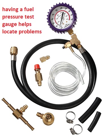
good fuel pressure consistently 40-42 psi and,
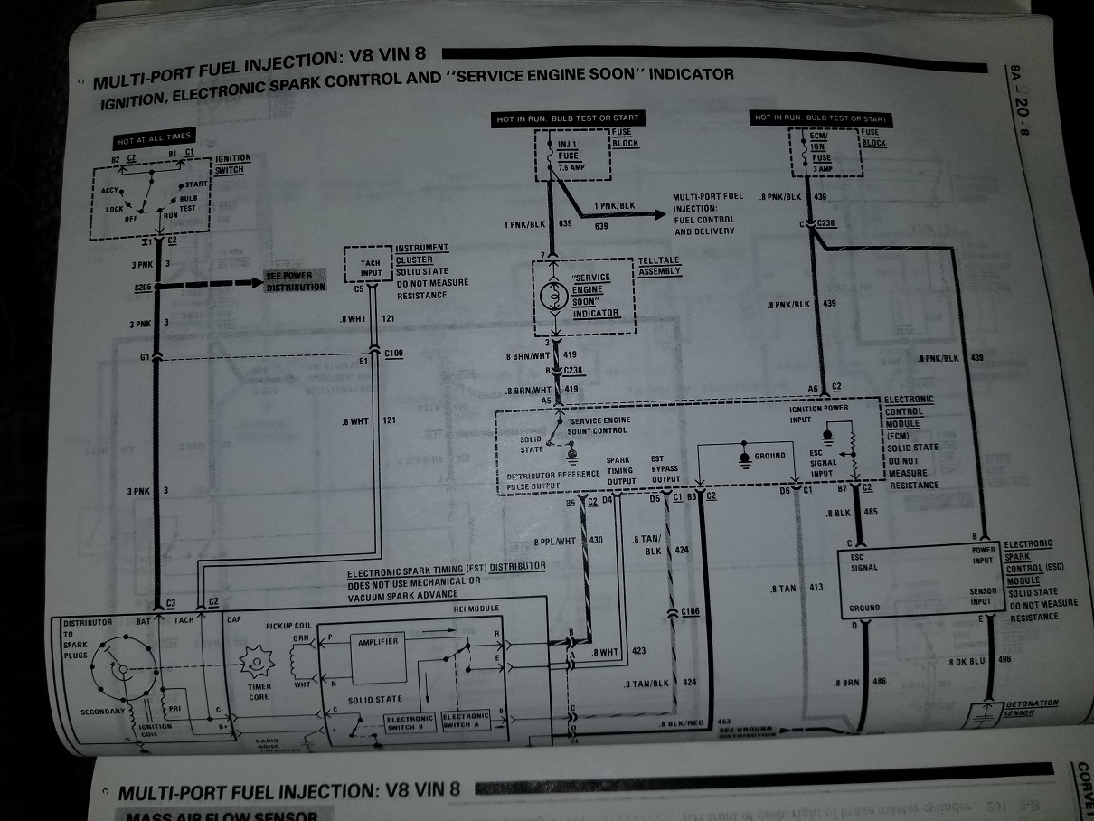
while I'm not overly impressed ignition spark at the spark plugs,
noid lights show injector harness is functional,
the tps is correctly set at .54 volts, IAC functions as designed.
it will start up and run fine until its turned off the first 2-3 times, in a row,
ignition timing is set at 8 degrees advanced and increases as expected if the engine rpms are increased,
the valves are properly adjusted,the firing orders verified the plugs are gaped at .043 ,
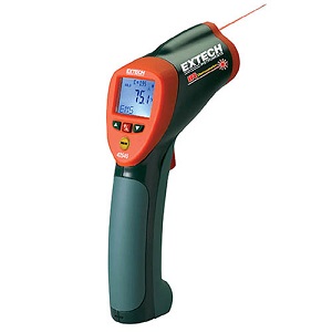
and show the engine runs decently, the infrared temp gun does not show any cylinder firing issues,
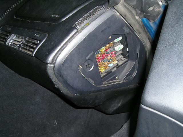
there are no blown electrical fuses. (Im begining to think this might be VATS related,)

you can let it run for 15 seconds- or 3 minutes or so, or for 5-7 minutes each time, its started,
and turn it off and it will restart instantly, the first 2-to sometimes 3 times,
but after the 3rd to 4th consecutive re-try or restart,
it spins over but won,t start?
theres no vacuum leaks and I don,t think its likely to be heat related,
as I can start the engine and turn it off about every 10 seconds and by the 4th time the no start condition starts,
and within only 40 seconds total run time its barely started to warm up
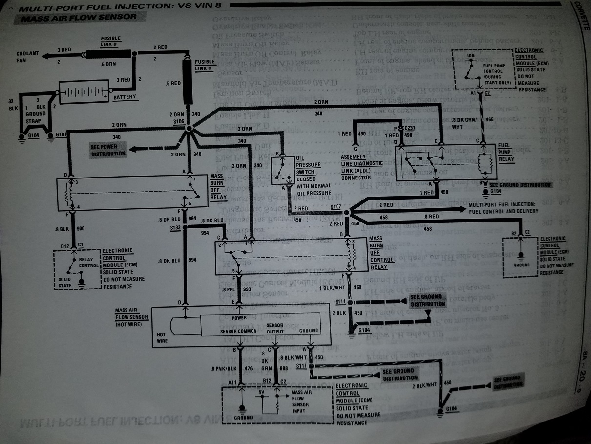
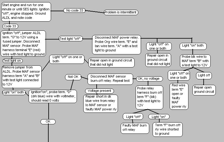
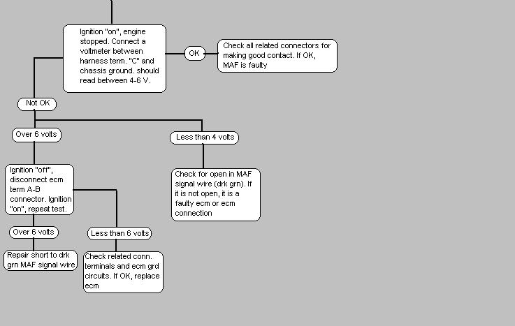
trouble code indicates a code #33 ( MAF sensor too much flow)
but the volt meter indicates the MAF is functional ?)
now I will track this down and report what I find,
so this might be helpful to others once I isolate and test and find the cause,
and I will as soon as I get someone too start the car, control the throttle and help watch gauges,
and let me use gauges and meters under the hood ,
but I,m curious if anyone else has run into this?
problems like this can be rather fun to sort out!
but at times it really helps to have two people as you can,t be two places at once!
theres nothing complicated, its all just isolate and test, and thinking logically,
and of course having the correct tools and a shop manual, and experience, helps
I'm sure its something like a defective sensor,
but at times having a friend that can start the car and play with the throttle,
while you verify sensor function, spark, fuel and oil pressure under the hood,
makes diagnosing the problem source much easier
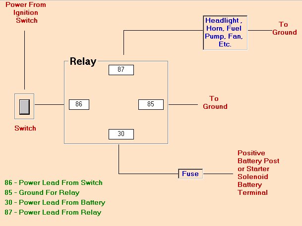
https://www.the12volt.com/relays/relaydiagrams.asp (read)
85 and 87a -> Ground
86 -> Power
30 -> Output
-30 = constant [positive (+)] power (usually wired directly to car battery)
-85 = coil ground (wired to the negative (-) battery terminal or any grounded metal panel in the car)
-86 = coil power (wired to the control source. could be a switch, or it could be the car's IGN or ACC circuit.)
-87 = switched [positive (+)] power output. (when the relay coil is powered, lead/pin 87 is connected to lead/pin 30)
-87a = [on 5 lead/pin relays only] this lead/pin is connected to lead/pin 30 when the coil is NOT powered.
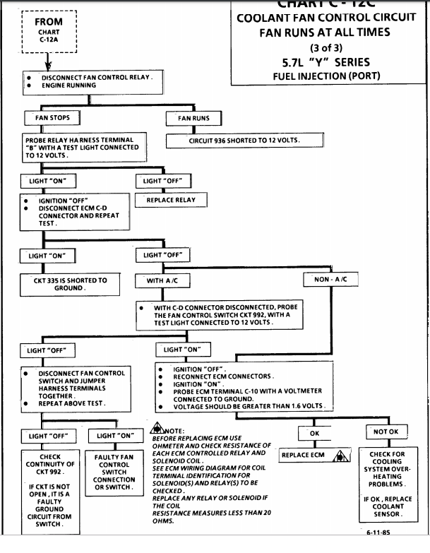
these charts are for the 1985-89 vette cooling fans

# Check fan fuses in the underhood fuse/relay panel
# Check fan relays (same location). Aside from getting out any electrical equipment to test the relay, you can swap it with another one (such as the fog lamp relay) and test for function. See if the relay works for the fog lamps and/or the swapped-in relay makes your fans work. Nearly all the relays in the panel are the same, except for maybe the ABS relay.
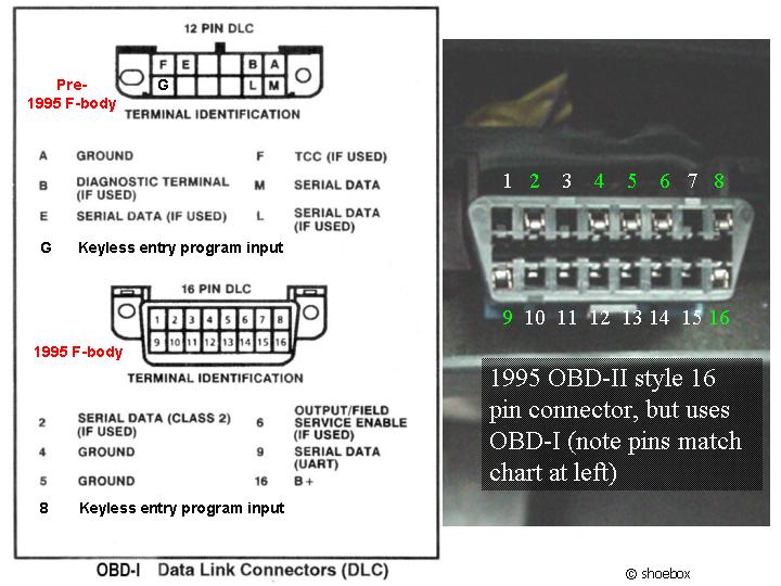
# You can jumper two pins on the DLC that should cause the fans to come on. 1993-1994 cars with the 12 pin DLC can jumper pins A and B. On a 1993, that is the same way that you would retrieve trouble codes from the ecm. The 1994 won't give you any codes, but the fans will engage. 1995-1997 uses pins 5 and 6 on the 16 pin DLC to initiate what is called "field service enable mode". That will cause the fans to come on and operate most sensors for sanity checking. After placing the jumper on the correct pins, turn the key to ON (don't start). If the fans work after jumpering the DLC, your PCM is capable of operating the fans and all fan wiring/relays should be ok.
# Deeper problems can be solved through testing and using the wiring schematic.
~Fans don't come on except when the a/c or SES is on~
~Temp gauge continues to rise with no automatic fan operation~
# With a scan tool, check to see what temp the PCM is seeing from the sensor in the water pump. Make sure you are aware of the temps the fans come on (stated in the beginning of this article). If the temp it sees is incorrectly low, it won't know to turn the fans on. Another possibility is that the temp is really ok, but the gauge is reading wrong. That is why you need to use the scan tool to see and compare the readings. Info on testing wiring and sensor can be found here.
# If that looks ok, then your PCM may have issues. You could always try resetting the PCM by pulling the PCM BAT fuse for about 30 seconds.
viewtopic.php?f=70&t=3504&p=9220#p9220
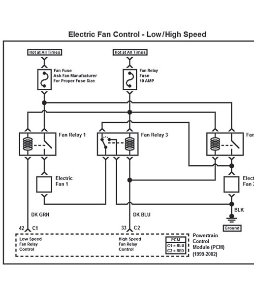
Testing the ECT (Engine Temperature) Sensors and Connections
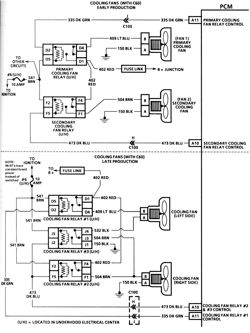
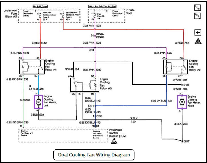
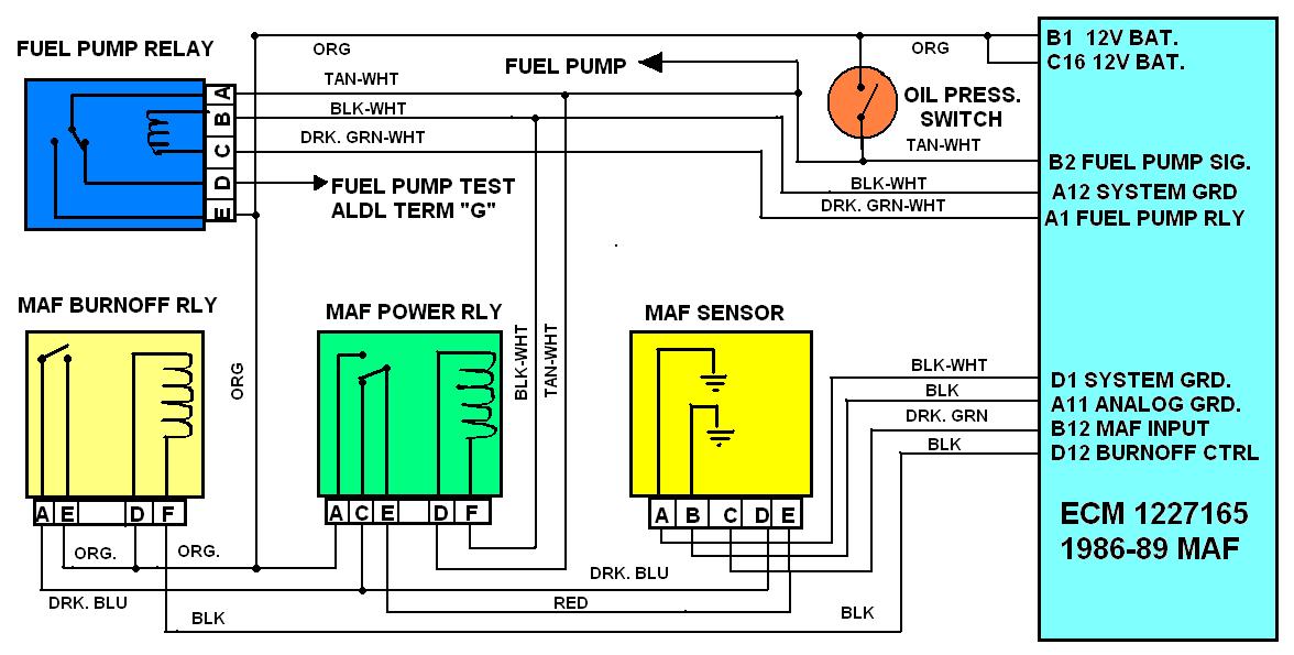
THE DIAGRAM ABOVE HAS THE CORRECT WIRE COLORS
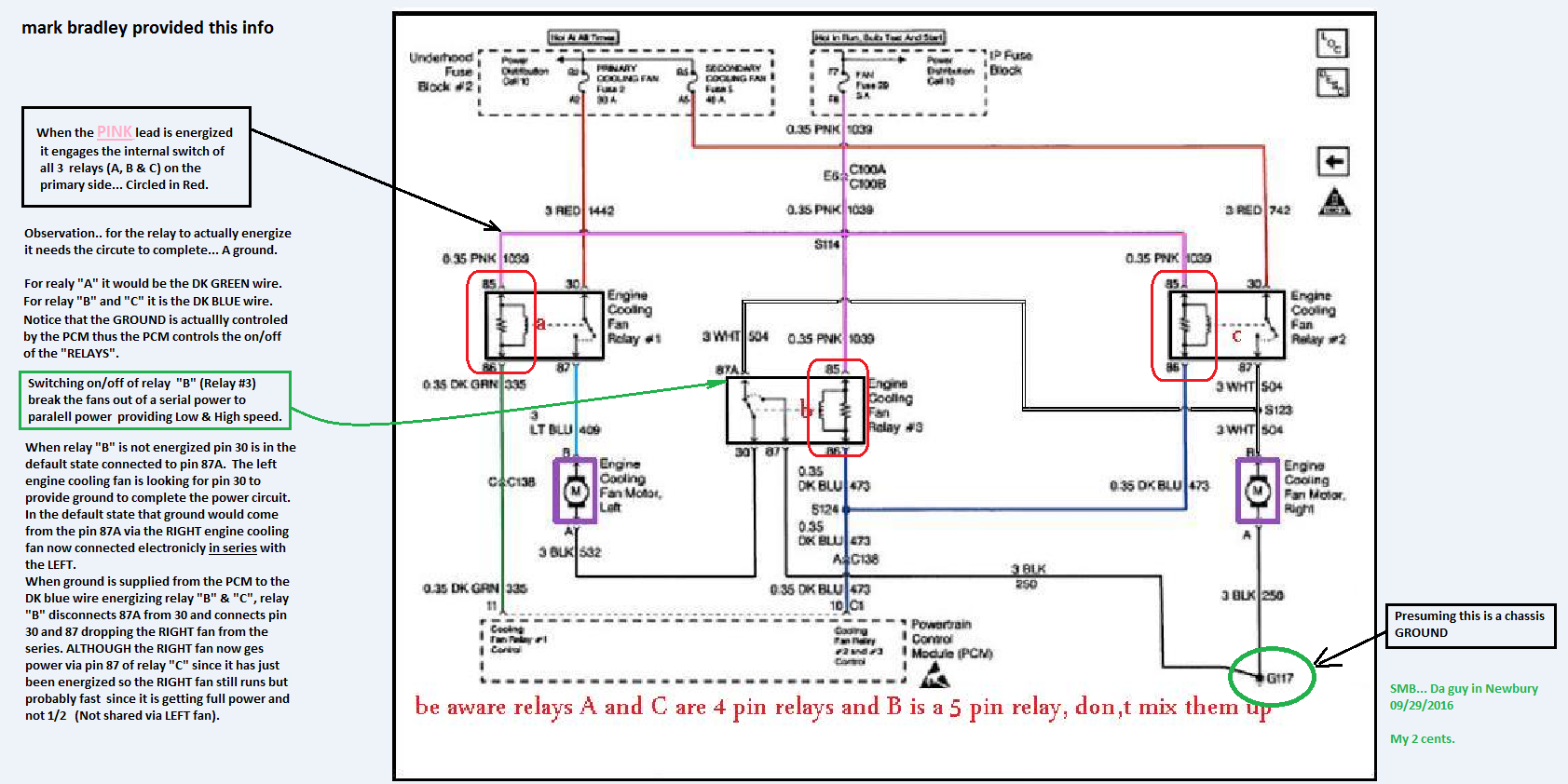
Pro tip before starting - Label your relays Relay 1, Relay 2, and Relay 3 according to the wiring diagram (your first post) and what your physical relays represent. Even if its just a sticky note. Get it all straight and stick to the same annotation while you troubleshoot.
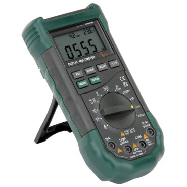
You'll need a multimeter than can measure DC voltage and continuity:
Remove all three relays so you're only dealing with the sockets
DC Voltage tests:
1. Confirm 12V between the socket for pin 85 and the negative battery terminal on all 3 relay sockets
2. Confirm 12v between the socket for pin 30 and the negative battery terminal on relay sockets 1 and 2
Continuity tests:
1. Confirm continuity with the end of the dark green wire and the socket for pin 86 for relay 1
2. Confirm continuity with the end of the dark blue wire and the socket for pin 86 for relay 2 AND relay 3.
3. Confirm continuity between the socket for pin 87 for relay 1 and side B of the left cooling fan connector
4. Confirm continuity between side A of the left cooling fan connector and side B of the right cooling fanconnector AND the socket for pin 87 for relay #2.
5. Confirm continuity between the socket for pin 87 for relay #3 and Negative Battery Terminal
6. Confirm continuity between side A of the right cooling connector and Negative Battery Terminal.
Do the steps in order and use the negative battery terminal for your connection when I specify to. Verifying at the negative battery terminal will ensure you're circuit is making a good connection to the chassis ground. If it doesn't make it all the way back to the battery, it's a crap ground and testing it my way will reveal the problem
ECT Temperature vs. Resistance Values
ºC ºF Ohms
100 212 177
90 194 241
80 176 332
70 158 467
60 140 667
50 122 973
45 113 1188
40 104 1459
35 95 1802
30 86 2238
25 77 2796
20 68 3520
15 59 4450
10 50 5670
5 41 7280
0 32 9420
-5 23 12300
-10 14 16180
-15 5 21450
-20 -4 28680
-30 -22 52700
-40 -40 100700
Use a Digital Volt Meter (DVM) set to ohms to measure resistance. Note: Use a high impedance meter (at least 10 megohm) when dealing with the PCM. Most modern DVMs will do, but your old analog meter can damage the PCM. It is also a good idea to get a " reference" from the meter you are working with. With the DVM on the ohms scale, touch the two meter leads together and note the ohm reading. It may not always be perfectly zero, but may be within a tenth or two. Now when you take an ohm reading, you will know what the meter will show when there is really no resistance.
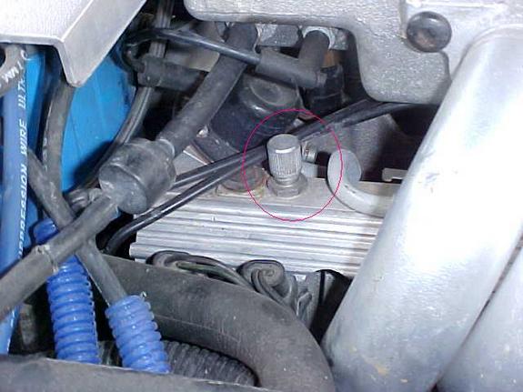
* The sensor in the head has only one terminal. This sensor is for the temperature indicator on the dashboard. Place one test lead on the sensor terminal and the other on a known good ground. Compare the reading to the table. If your car is cold from sitting overnight, the reading should be close to ambient temperature.
* The sensor in the water pump has two terminals. This sensor is for the temperature input to the PCM. Place a test lead on each of the sensor terminals to take the reading. (When reading resistance, it does not matter which lead goes to which terminal)
If the sensor seems to be ok, you may also need to test at the harness connector for proper lead conditions. Use your test meter set on the dc voltage scale to do this. You will need the key in the RUN position, but don't have to start the car.
* For the one lead connector at the head, place the red test lead on the connector terminal and the black test lead to a known good ground. With the key ON, you should read battery voltage (+12vdc or close to it). You can also ground the lead and see if the gauge in the car deflects to full hot.
o If you get no voltage, switch the meter to ohms to see if the lead is grounded.
o No voltage or no ground mean that the lead is open.
o If the gauge is at full hot all the tme, the lead is grounded back toward the gauge. It could be possible for the lead to be pinched and grounded toward the gauge and broken and open back toward the sensor (like in the case of the wire getting caught somewhere during some major engine work). Physically tracing the wire from the sensor into the harness should locate the problem.
* The two lead connector at the water pump has a black (ground) lead and a PCM +5vdc power lead (probably yellow). Place the black meter test lead to black connector lead and the red meter test lead to the other connector lead (yellow on my 1995). You should read +5vdc because this is monitoring voltage being supplied from the PCM.
* If you get no reading:
o Test the yellow lead by placing the DVM red lead on it and the DVM black lead to ground. A +5vdc reading will indicate the lead is ok.
+ If you get no voltage, switch the meter to ohms to see if the lead is grounded.
+ No voltage or no ground mean that the lead is open.
o You can test the black connector lead by using the ohms scale on the DVM. Place the DVM black lead to ground. Place the DVM red lead to the black lead of the connector. If the lead is ok, you will get an ohm reading close to zero. If you get no reading or a very high one, the lead is open or partially open.
* OBD-I DTCs 14 and 15 or OBD-II DTCs P0117 and P0118 are typically associated with problems the PCM sees with the sensors or circuits.
Footnote: If you ever have to test the IAT, it operates the same as the two lead coolant sensor. The same temp vs. resistance table above is applicable to the IAT, as well as the +5vdc lead and ground wire at the harness connector.
any thoughts gentlemen?
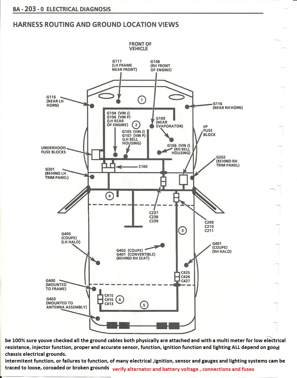
be aware the electrical grounds 104-105,106,107 must be checked and firmly connected to the engine
a factory shop manual and a v.o.m. meter come in handy for testing!
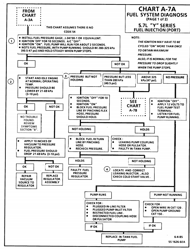
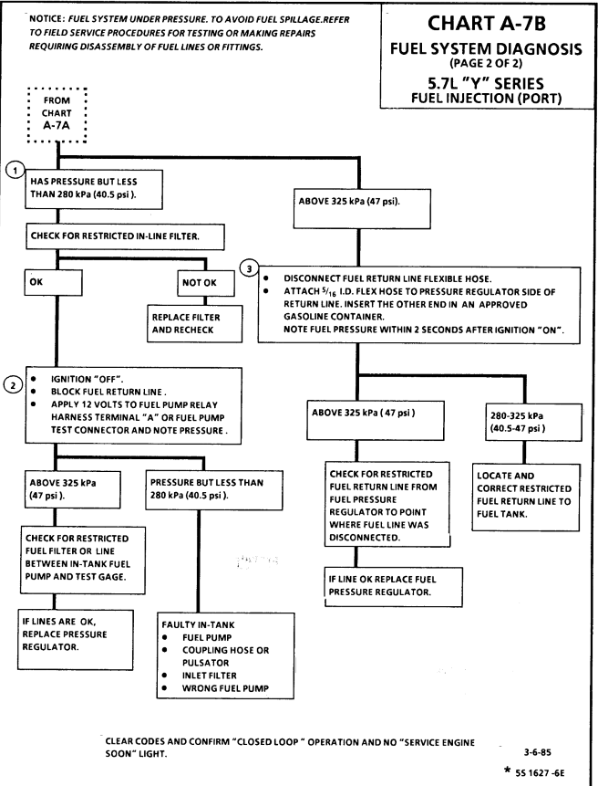
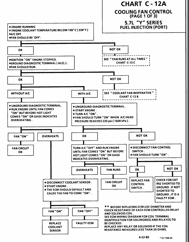
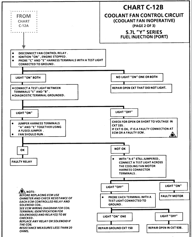
http://www.chevythunder.com/Flow chart index.htm
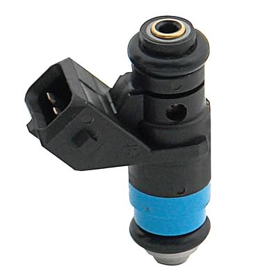
the factory installed, tuned port high ohms injectors, should read between about 11 ohms and 13 ohms resistance
http://garage.grumpysperformance.co...ouble-shooting-rebuilding-hei-ignitions.2798/
potentially related threads, these links hold a great deal of info
http://garage.grumpysperformance.com/index.php?threads/c4-c5-corvette-trouble-codes.2697/#post-91077
http://garage.grumpysperformance.com/index.php?threads/gm-tpi-stalling-diagnosis.15194/#post-86992
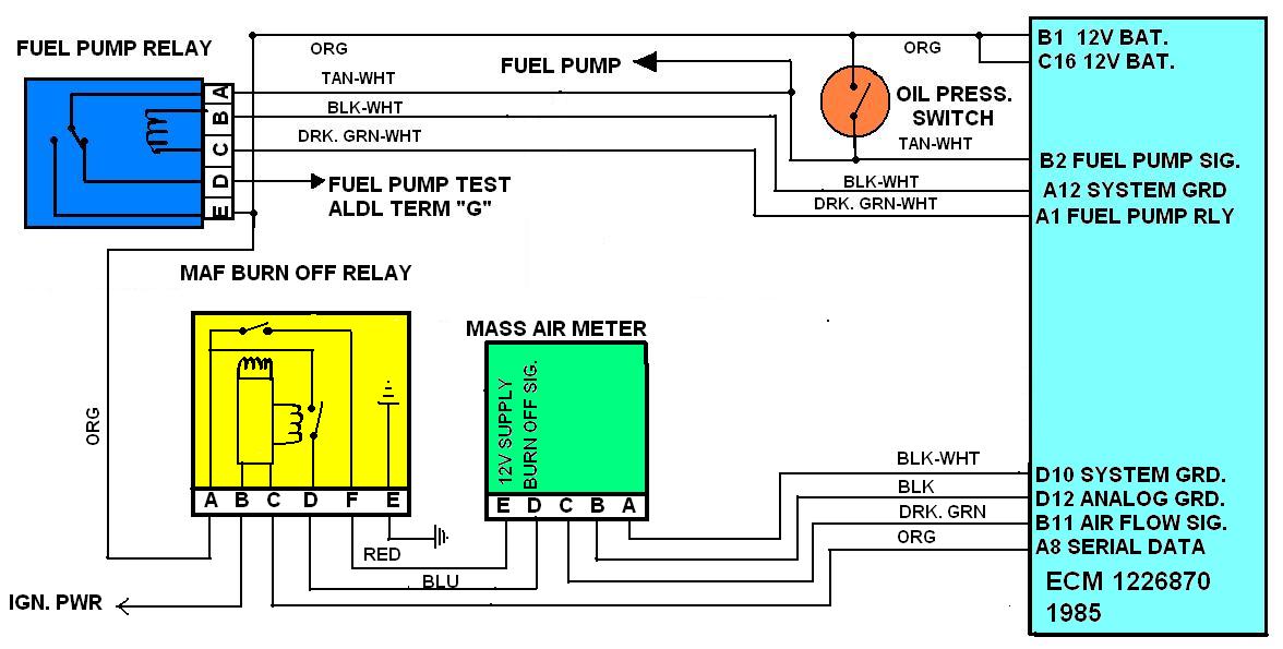
http://garage.grumpysperformance.com/index.php?threads/maf-burn-off-relay-info.661/#post-908
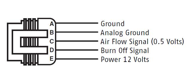
http://garage.grumpysperformance.com/index.php?threads/testing-1985-89-m-a-f-sensor.1475/#post-3325
http://garage.grumpysperformance.co...oven-facts-if-your-in-doubt.13051/#post-84695
http://garage.grumpysperformance.co...-won-t-start-intermittently.14212/#post-72158
http://garage.grumpysperformance.co...urrent-flow-grounds-and-more.3504/#post-54624
http://garage.grumpysperformance.co...start-right-back-up-and-run.10739/#post-46893
http://garage.grumpysperformance.co...-idles-and-sometimes-stalls.10688/#post-46308
http://garage.grumpysperformance.co...m-with-how-your-c4-corvette-runs-badly.15212/
http://garage.grumpysperformance.com/index.php?threads/1989-corvette-shows-a-trouble-code-33.15594/
the engines got good compression, and it runs decently when first started and will do so unless its engine is turned off,
this is intermittent problem, making it a bit harder to isolate,
the engine does not cut out or stall if left running,
that engine starts right up, if cold (sitting over night )
instantly crank up and run, its got good oil pressure, 37-39 psi cold, and does not drop below 30 psi at idle.
good fuel pressure consistently 40-42 psi and,
while I'm not overly impressed ignition spark at the spark plugs,
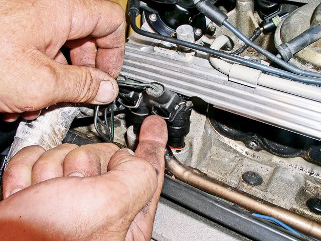
noid lights show injector harness is functional,
the tps is correctly set at .54 volts, IAC functions as designed.
it will start up and run fine until its turned off the first 2-3 times, in a row,
ignition timing is set at 8 degrees advanced and increases as expected if the engine rpms are increased,
the valves are properly adjusted,the firing orders verified the plugs are gaped at .043 ,
and show the engine runs decently, the infrared temp gun does not show any cylinder firing issues,
there are no blown electrical fuses. (Im begining to think this might be VATS related,)
you can let it run for 15 seconds- or 3 minutes or so, or for 5-7 minutes each time, its started,
and turn it off and it will restart instantly, the first 2-to sometimes 3 times,
but after the 3rd to 4th consecutive re-try or restart,
it spins over but won,t start?
theres no vacuum leaks and I don,t think its likely to be heat related,
as I can start the engine and turn it off about every 10 seconds and by the 4th time the no start condition starts,
and within only 40 seconds total run time its barely started to warm up
trouble code indicates a code #33 ( MAF sensor too much flow)
but the volt meter indicates the MAF is functional ?)
now I will track this down and report what I find,
so this might be helpful to others once I isolate and test and find the cause,
and I will as soon as I get someone too start the car, control the throttle and help watch gauges,
and let me use gauges and meters under the hood ,
but I,m curious if anyone else has run into this?
problems like this can be rather fun to sort out!
but at times it really helps to have two people as you can,t be two places at once!
theres nothing complicated, its all just isolate and test, and thinking logically,
and of course having the correct tools and a shop manual, and experience, helps
I'm sure its something like a defective sensor,
but at times having a friend that can start the car and play with the throttle,
while you verify sensor function, spark, fuel and oil pressure under the hood,
makes diagnosing the problem source much easier
https://www.the12volt.com/relays/relaydiagrams.asp (read)
85 and 87a -> Ground
86 -> Power
30 -> Output
-30 = constant [positive (+)] power (usually wired directly to car battery)
-85 = coil ground (wired to the negative (-) battery terminal or any grounded metal panel in the car)
-86 = coil power (wired to the control source. could be a switch, or it could be the car's IGN or ACC circuit.)
-87 = switched [positive (+)] power output. (when the relay coil is powered, lead/pin 87 is connected to lead/pin 30)
-87a = [on 5 lead/pin relays only] this lead/pin is connected to lead/pin 30 when the coil is NOT powered.
these charts are for the 1985-89 vette cooling fans
# Check fan fuses in the underhood fuse/relay panel
# Check fan relays (same location). Aside from getting out any electrical equipment to test the relay, you can swap it with another one (such as the fog lamp relay) and test for function. See if the relay works for the fog lamps and/or the swapped-in relay makes your fans work. Nearly all the relays in the panel are the same, except for maybe the ABS relay.
# You can jumper two pins on the DLC that should cause the fans to come on. 1993-1994 cars with the 12 pin DLC can jumper pins A and B. On a 1993, that is the same way that you would retrieve trouble codes from the ecm. The 1994 won't give you any codes, but the fans will engage. 1995-1997 uses pins 5 and 6 on the 16 pin DLC to initiate what is called "field service enable mode". That will cause the fans to come on and operate most sensors for sanity checking. After placing the jumper on the correct pins, turn the key to ON (don't start). If the fans work after jumpering the DLC, your PCM is capable of operating the fans and all fan wiring/relays should be ok.
# Deeper problems can be solved through testing and using the wiring schematic.
~Fans don't come on except when the a/c or SES is on~
~Temp gauge continues to rise with no automatic fan operation~
# With a scan tool, check to see what temp the PCM is seeing from the sensor in the water pump. Make sure you are aware of the temps the fans come on (stated in the beginning of this article). If the temp it sees is incorrectly low, it won't know to turn the fans on. Another possibility is that the temp is really ok, but the gauge is reading wrong. That is why you need to use the scan tool to see and compare the readings. Info on testing wiring and sensor can be found here.
# If that looks ok, then your PCM may have issues. You could always try resetting the PCM by pulling the PCM BAT fuse for about 30 seconds.
viewtopic.php?f=70&t=3504&p=9220#p9220
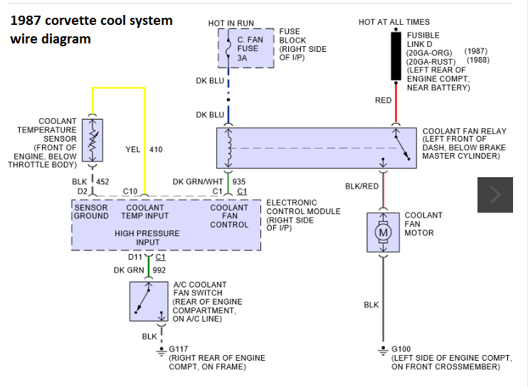
Testing the ECT (Engine Temperature) Sensors and Connections
THE DIAGRAM ABOVE HAS THE CORRECT WIRE COLORS
Pro tip before starting - Label your relays Relay 1, Relay 2, and Relay 3 according to the wiring diagram (your first post) and what your physical relays represent. Even if its just a sticky note. Get it all straight and stick to the same annotation while you troubleshoot.
You'll need a multimeter than can measure DC voltage and continuity:
Remove all three relays so you're only dealing with the sockets
DC Voltage tests:
1. Confirm 12V between the socket for pin 85 and the negative battery terminal on all 3 relay sockets
2. Confirm 12v between the socket for pin 30 and the negative battery terminal on relay sockets 1 and 2
Continuity tests:
1. Confirm continuity with the end of the dark green wire and the socket for pin 86 for relay 1
2. Confirm continuity with the end of the dark blue wire and the socket for pin 86 for relay 2 AND relay 3.
3. Confirm continuity between the socket for pin 87 for relay 1 and side B of the left cooling fan connector
4. Confirm continuity between side A of the left cooling fan connector and side B of the right cooling fanconnector AND the socket for pin 87 for relay #2.
5. Confirm continuity between the socket for pin 87 for relay #3 and Negative Battery Terminal
6. Confirm continuity between side A of the right cooling connector and Negative Battery Terminal.
Do the steps in order and use the negative battery terminal for your connection when I specify to. Verifying at the negative battery terminal will ensure you're circuit is making a good connection to the chassis ground. If it doesn't make it all the way back to the battery, it's a crap ground and testing it my way will reveal the problem
ECT Temperature vs. Resistance Values
ºC ºF Ohms
100 212 177
90 194 241
80 176 332
70 158 467
60 140 667
50 122 973
45 113 1188
40 104 1459
35 95 1802
30 86 2238
25 77 2796
20 68 3520
15 59 4450
10 50 5670
5 41 7280
0 32 9420
-5 23 12300
-10 14 16180
-15 5 21450
-20 -4 28680
-30 -22 52700
-40 -40 100700
Use a Digital Volt Meter (DVM) set to ohms to measure resistance. Note: Use a high impedance meter (at least 10 megohm) when dealing with the PCM. Most modern DVMs will do, but your old analog meter can damage the PCM. It is also a good idea to get a " reference" from the meter you are working with. With the DVM on the ohms scale, touch the two meter leads together and note the ohm reading. It may not always be perfectly zero, but may be within a tenth or two. Now when you take an ohm reading, you will know what the meter will show when there is really no resistance.
* The sensor in the head has only one terminal. This sensor is for the temperature indicator on the dashboard. Place one test lead on the sensor terminal and the other on a known good ground. Compare the reading to the table. If your car is cold from sitting overnight, the reading should be close to ambient temperature.
* The sensor in the water pump has two terminals. This sensor is for the temperature input to the PCM. Place a test lead on each of the sensor terminals to take the reading. (When reading resistance, it does not matter which lead goes to which terminal)
If the sensor seems to be ok, you may also need to test at the harness connector for proper lead conditions. Use your test meter set on the dc voltage scale to do this. You will need the key in the RUN position, but don't have to start the car.
* For the one lead connector at the head, place the red test lead on the connector terminal and the black test lead to a known good ground. With the key ON, you should read battery voltage (+12vdc or close to it). You can also ground the lead and see if the gauge in the car deflects to full hot.
o If you get no voltage, switch the meter to ohms to see if the lead is grounded.
o No voltage or no ground mean that the lead is open.
o If the gauge is at full hot all the tme, the lead is grounded back toward the gauge. It could be possible for the lead to be pinched and grounded toward the gauge and broken and open back toward the sensor (like in the case of the wire getting caught somewhere during some major engine work). Physically tracing the wire from the sensor into the harness should locate the problem.
* The two lead connector at the water pump has a black (ground) lead and a PCM +5vdc power lead (probably yellow). Place the black meter test lead to black connector lead and the red meter test lead to the other connector lead (yellow on my 1995). You should read +5vdc because this is monitoring voltage being supplied from the PCM.
* If you get no reading:
o Test the yellow lead by placing the DVM red lead on it and the DVM black lead to ground. A +5vdc reading will indicate the lead is ok.
+ If you get no voltage, switch the meter to ohms to see if the lead is grounded.
+ No voltage or no ground mean that the lead is open.
o You can test the black connector lead by using the ohms scale on the DVM. Place the DVM black lead to ground. Place the DVM red lead to the black lead of the connector. If the lead is ok, you will get an ohm reading close to zero. If you get no reading or a very high one, the lead is open or partially open.
* OBD-I DTCs 14 and 15 or OBD-II DTCs P0117 and P0118 are typically associated with problems the PCM sees with the sensors or circuits.
Footnote: If you ever have to test the IAT, it operates the same as the two lead coolant sensor. The same temp vs. resistance table above is applicable to the IAT, as well as the +5vdc lead and ground wire at the harness connector.
any thoughts gentlemen?
be aware the electrical grounds 104-105,106,107 must be checked and firmly connected to the engine
a factory shop manual and a v.o.m. meter come in handy for testing!
http://www.chevythunder.com/Flow chart index.htm
the factory installed, tuned port high ohms injectors, should read between about 11 ohms and 13 ohms resistance
http://garage.grumpysperformance.co...ouble-shooting-rebuilding-hei-ignitions.2798/
potentially related threads, these links hold a great deal of info
http://garage.grumpysperformance.com/index.php?threads/c4-c5-corvette-trouble-codes.2697/#post-91077
http://garage.grumpysperformance.com/index.php?threads/gm-tpi-stalling-diagnosis.15194/#post-86992
http://garage.grumpysperformance.com/index.php?threads/maf-burn-off-relay-info.661/#post-908
http://garage.grumpysperformance.com/index.php?threads/testing-1985-89-m-a-f-sensor.1475/#post-3325
http://garage.grumpysperformance.co...oven-facts-if-your-in-doubt.13051/#post-84695
http://garage.grumpysperformance.co...-won-t-start-intermittently.14212/#post-72158
http://garage.grumpysperformance.co...urrent-flow-grounds-and-more.3504/#post-54624
http://garage.grumpysperformance.co...start-right-back-up-and-run.10739/#post-46893
http://garage.grumpysperformance.co...-idles-and-sometimes-stalls.10688/#post-46308
http://garage.grumpysperformance.co...m-with-how-your-c4-corvette-runs-badly.15212/
http://garage.grumpysperformance.com/index.php?threads/1989-corvette-shows-a-trouble-code-33.15594/
Last edited: