Input on electric fuel pump selection

87vette81big said:
The best way would to be use a fuel cell Neal.
15-30 gallons. Or fabricate a fuel cell from scratch.
Not the easiest for the home mechanic to do without prior experience .

Fabrication is not an issue as I worked in that field for 10 years,

My last post is not very clear on what my question is,

With the fuel pump being behind the half shafts there is no easy path to get the fuel line from the discharge of the pump to the forward side of the half shafts to within the frame rails without passing under the diff or close to the spinning shafts.

I was curious if someone had some insight on this issue?

Neal
 
Without clear photos of the underside of your C3 Neal, only way I can think of tonight is bringing both fuel lines up and over the top of the fuel tank and route around and. away from the IRS DIFF & Halfshafts.
 
87vette81big said:
Without clear photos of the underside of your C3 Neal, only way I can think of tonight is bringing both fuel lines up and over the top of the fuel tank and route around and. away from the IRS DIFF & Halfshafts.

I need to remove a shield that is between the tank and the rear wall of the cab that may give me some room to rout the lines.

I'll need to get it on the lift and remove the tank and shield to see what I got in there,

I am waiting on the sump to get here before I remove the tank so it may be a few days before I can really get an idea of how I will rout the lines.

Neal
 
On Very Difficult Fuel System Layouts Neal I Have Used Earls & Aeroquip AN Aluminium Bulkhead connectors.
To Pass the Fuel Line through Solid sheet metal & Car frame members.
Bulkhead connectors also available in Stainless steel for higher tensile strength.

I have routed Fuel lines through Rocker panels. Hid the lines and gived plenty of ground clearance on Unibody constructed cars.

OK Also to drill through Unibody torque boxes.
Plan strategic place hole in the center of torque box.
Don't lose any Torsional and Beaming strength.
How you drill holes in semi truck frames and don't have any frame cracking issues.

I don't favor the idea of using 5/8" hard stainless steel lines.
Very difficult to form without a specialized tubing mandrel bender.
Not any safer than Stainless steel jacketed Race Fuel Hose.
Hard Tubing prone to cracking in High performance Race Applications.

Stainless steel Jacked Race Hose can be routed much easier in tough routing situations where nothing else convential can.
Also not prone to vibration and shock induced cracking.


BR
 
legerwn said:
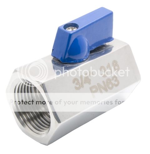
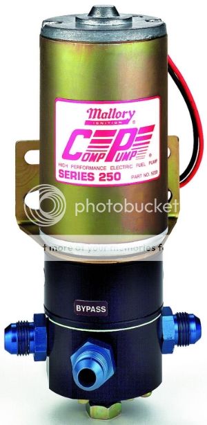
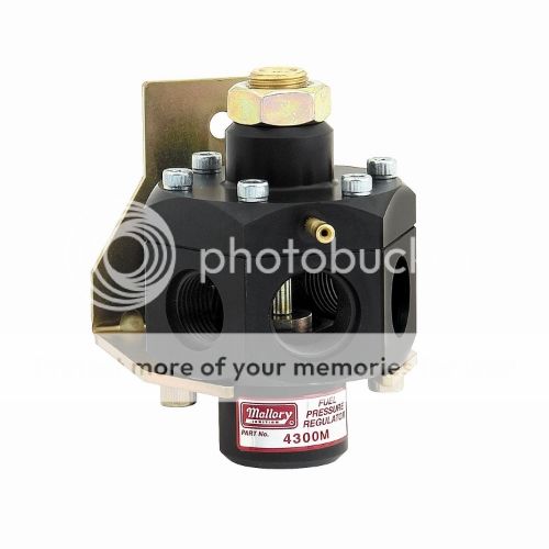
I ordered the Mallory 5250 Pump and the Mallory 4300M regulator, also ordered 2 -3/4" SS mini ball valves for the sump (.49" bore).


The pump was hard to get without waiting till November as they are on back order just about everywhere. I stumbled across Pep Boy's web site where the pump was heavily discounted and was able to add the 25% discount along with free shipping on top of the discounted pump and they have the pump on hand so it shipped right away.

I'll be using both 8AN sump fittings to feed the fuel/water separator so I needed two valves.

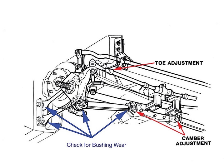
Grumpy, looking at a post on the form there is pic of the rear of a vette with an Aeromotive A1000 pump plumbed from the tank to the pump. (could you post a link?)Not sure if you were doing the work on this car or not but am needing ideas on how to get the supply line form the rear of the car past the half shafts to the frame rail. The OEM line passes over the top of the frame near the tire and I don't think I'll have room to get two 5/8" lines in that area. I've seen pics were the lines were run below the diff with a shield, I don't get a good fuzzy feeling about running them there.

any ideas on how to get the lines from the rear of the car to the frame rails ahead of the half shafts?

Neal
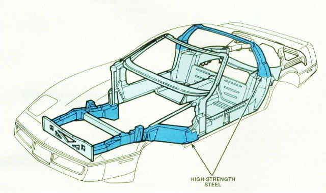
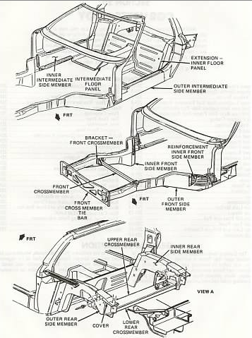
Id be looking at running the lines either inside or or along side of the frame rails
rearsuspension5xxa.jpg

C4chassis.jpg

c4framehj.png
 
Beats welding on a gas tank Neal.
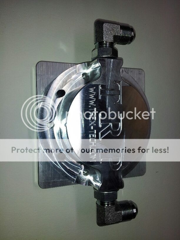
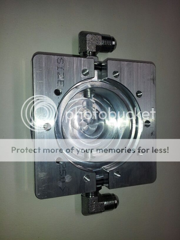
I take its a true bolt on billet sump.

New part to me.
 
legerwn said:
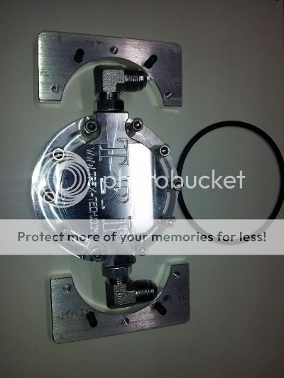
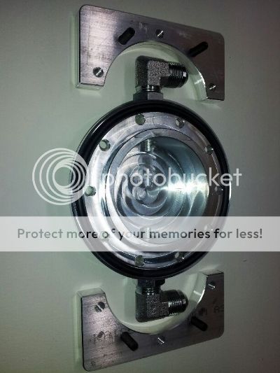
this is the sump i'll be installing on my tank;


Neal

052814a.jpg


052814xa.jpg


http://www.officedepot.com/a/products/1 ... esh-Paper/

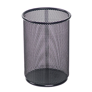
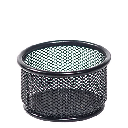
that looks like its custom designed, to have one of these $4 expanded steel mesh pencil holders, or paper clip cup, cylindrical screens added which are about the size of your average coffee cup mounted open end facing down over the sump as a debris screen, which I'm rather surprised to see is not already a component
http://www.officedepot.com/a/products/1 ... esh-Jumbo/
 
I think it costs more than $3.99 Grumpy.
Move the decimal over 2 places to the right.

I have learned C3, C5, &C6 Corvette guys are going to do what they want.
All seem to refuse to loose convenient .
C4 guys more apt to use Vintage Race car Tech & hardware.
 
The way gasoline sloshes around Neal, I would only run your 496 BBC Hard with 10-15 gallons of gas in the tank with the bolt in sump shown.
I wouldn't try just 5 gallons as drag racers do to save weight .

All Big Blocks are fuel hungry WOT.
Chevy, Ford, Hemi, 440 , &455 Pontiac.
 
Grumpy with the Perma-Cool fuel water separator I didn't think I would need a screen in the tank.

87vette I was planning to install a shield in the tank around the sump to keep fuel at the sump under hard acceleration.

the bottom of the C3 tank is on an angle already toward the front of the car (deep in the front) so once the sump is mounted the fuel should stay in the sump.

What do yawl think about the two 8AN fittings, was going to look for some that may have a longer radius for better flow. They look like a ORB fittings so I may be able to come up with something better.

Neal
 
I need to pull the tank and see what my options are to run the lines and also need to see if I have room to add the return fitting on the top of the tank.

Neal
 
With the Billet sump shown Neal, I would like a Y-setup inlet to the Mallory Comp 250 pump.
2 #8 into a Y- union.
#10AN TO the pump.
Space available yet to be seen.
 
It doesn't take long to spend $100, 200, 400, $1k in AN Fittings and Hardware Neal.
Planning aheah a must.
Write down all on paper.
Review the Fuel system layout.
Make a Blueprint Drawing.
 
I agree with both lines feeding the pump, I had mentioned in one of my prior post that I had planned to run both 8AN lines to the filter and then both to a Y-fitting 8AN x 8AN x 10AN to the pump but the pump has a 8AN inlet so I'll have to stay with the 8AN in and out on the Y-fitting.


Something like this

I agree the system needs to be planned out to make sure you've done everything possible to make it work.

Neal
 
parts are starting to show up at the door now, waiting on the filter right now. I think I'm going to try and run the fuel lines up the back of the motor to try and stay away from the exhaust. The engine compartment is rather small in a C3 with a BB installed.

One thing that has got me questioning the line sizes is the post that Grumpy posted of the carb inlet fittings and looking at the regulator port sizing. The inlet fittings and the carb seats are rather small so why do the lines need to be so large?

I can see why a return/bypass regulator is a must, when looking at the inlet port of a dead head regulator.

Is there an advantage to running the largest carb needle and seat that one can install?

I know the alcohol seats are very large compared to the gasoline seats.

Neal
 
When your building a 700hp plus engine ,the lines need to SUPPLY the carb with no significant flow restriction, most carbs will flow reasonably well and make decent power ,provided the fuel supply at the carbs inlet port is a consistent 5psi-5.5 psi and the volume is sufficient to meet demand which under high inertial loads is usually rather difficult to maintain when the engine starts to need more than 60-70 gal per hour and with a 700hp engine and good traction G loads can be rapidly changing and well in excess of 2 Gs.
youll want too keep in mind that most cars come with 3/8" or smaller fuel lines, and that the aftermarket fittings listed to fit AN#6 OR 3/8" FLEX FUEL LINES RARELY IF EVER HAVE INTERNAL CROSS SECTIONAL AREAS ALLOWING ANYTHING APPROACHING THE PLOW POTENTIAL OF A STRAIT SECTION OF FUEL LINE.
while a AN#6 fuel line can in theory support nearly 600 hp, once you run it through several fittings , filters and flex line the flow rates usually significantly lower than you might imagine.
 
With the Holidays and all I haven't had time to work on the car,

I was able to order the hose to plumb the fuel system at the tank, I decided to use Parker push-lok hose in -8 and run dual fuel supply to the pump.

My lift is not covered so I'll have to wait for a little good weather to get it installed.

Parker Push-Lok hose;

 
Back
Top