I was recently asked if the ratio between the intake port flow and exhaust was critical to making power , for those few that have not heard the term it refers to the ratio of intake port flow in cfm to exhaust port flow measured in cfm on a flow bench, this is normally done a 28" of water weight vacuum as a semi standard.
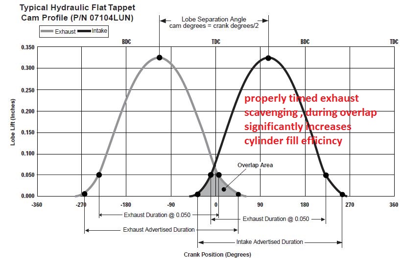
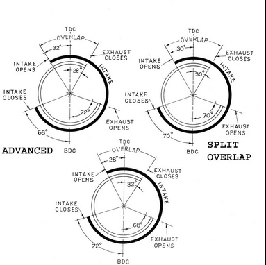
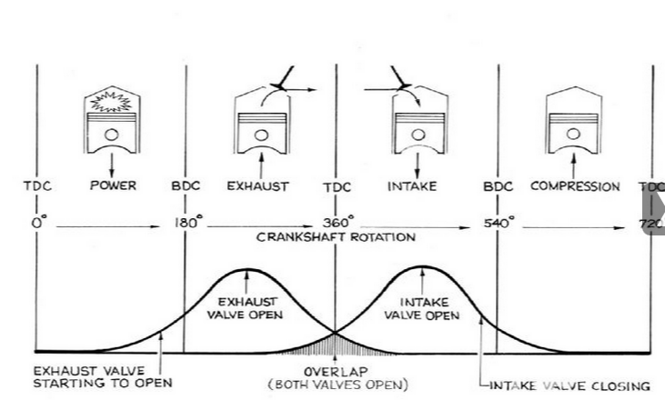
the problem is that intake and exhaust valves open and close several dozen times a second, over most of the engines power band and intake ports see between plus 1psi to minus 30 plus psi which fluctuates rapidly and the exhaust valve sees minus 30 plus psi- a positive 600 psi at different parts of the engines repeated trip thru its 720 degree cycle its rather common to see charts like this one
(I,ll post here below)
showing the flow at each lift , measured at a set lift and constant air flow rate, at every .100, .200,.300,.400,.500,.600 etc. that also list the I/E ratio,
http://users.erols.com/srweiss/tablehdc.htm
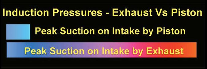
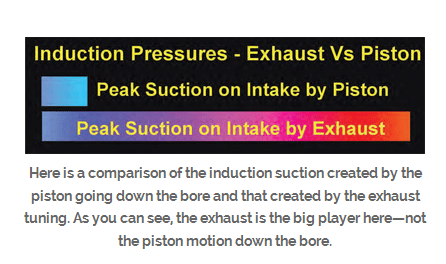
the truth here is that larger valves have the potential to flow more gases, but the intake is generally larger because its acted upon by both outside air pressure (14.7 PSI at sea level) and inertial forces the rapidly exiting exhaust flow induces<(EXHAUST SCAVENGING),which can easily exceed the draw the outside air pressure induces by several times
A CORRECTLY TUNED SET OF HEADERS , MATCHED TO A CORRECTLY DESIGNED CAM TIMING HAS A SIGNIFICANT EFFECT ON INTAKE FLOW AND CYLINDER SCAVENGING EFFICIENCY, EXHAUST SCAVENGING CAN BE 5 TIMES STRONGER THAN THE PISTON, MOVEMENT INDUCED NEGATIVE PRESSURE (VACUUM) IN THE INTAKE RUNNERS
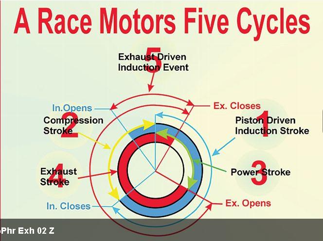
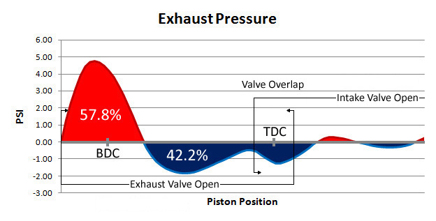
but keep in mind the EXHAUST gases are much higher, and once the exhaust valve opens they are PHYSICALLY forced to exit by the piston on the exhaust stroke and the inertia of the rapidly exiting exhaust , from the previous cylinder , tending to drag it out , which both greatly increase efficiency, thus the valve size can be smaller.
youll commonly see intake to exhaust ratios of about 75% on the exhaust to intake flow rates as quoted as ideal, but the truth is , from what Ive seen ,that both cam timing and exhaust primary diameter and length tuning can be used to make most engines run fairly decent at most rpm ranges, and close to ideally over a narrow rpm range.
yes I prefer as high an exhaust to intake ratio as I can get and if I can get a 70%-80% flow rate thats great, especially if your using nitrous, as a power booster, but maintaining that ratio is not critical and in most cases a longer duration on the exhaust cam timing, or changes in the header design can compensate for a less ideal exhaust ratio, if you use a low restriction exhaust behind the headers collector
that questions a bit like asking how good a girl might be in bed based on the color of her hair brush, yes theres a mathematical formula , in fact several, but theres a whole bunch of factors that determine the results, like cam timing, compression,cylinder head flow, back pressure,engine displacement , header primary and collector length and diameter,exhaust temps,etc.
the more back pressure the exhaust system beyond the header collectors has the less effective the headers will be, but if you have a low restriction exhaust and a ram tuned intake with a matched cam timing, a tuned header can in some cases produce gains in excess of 60 hp.
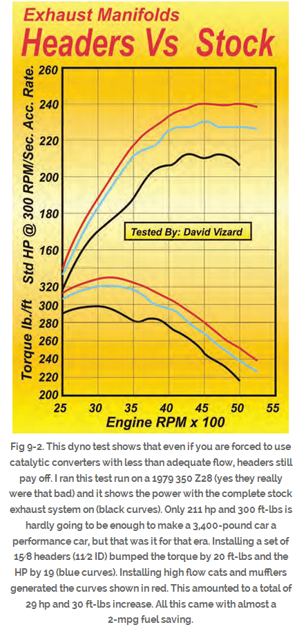
as a general rule Id say your safe expecting a 25-40 hp increase in peak hp from good long tube tuned headers over stock cast iron exhaust manifolds that come on most passenger cars, but with properly matched components on a high compression engine more can be gained.
READ THESE
http://victorylibrary.com/mopar/header-tech-c.htm
http://forum.grumpysperformance.com/viewtopic.php?f=56&t=495&p=613#p613
http://forum.grumpysperformance.com/viewtopic.php?f=56&t=1303
viewtopic.php?f=56&t=572&p=35352&hilit=rams+horn#p35352
http://forum.grumpysperformance.com/viewtopic.php?f=56&t=185
http://www.chevydiy.com/chevy-small-block-engine-guide-exhaust-systems/
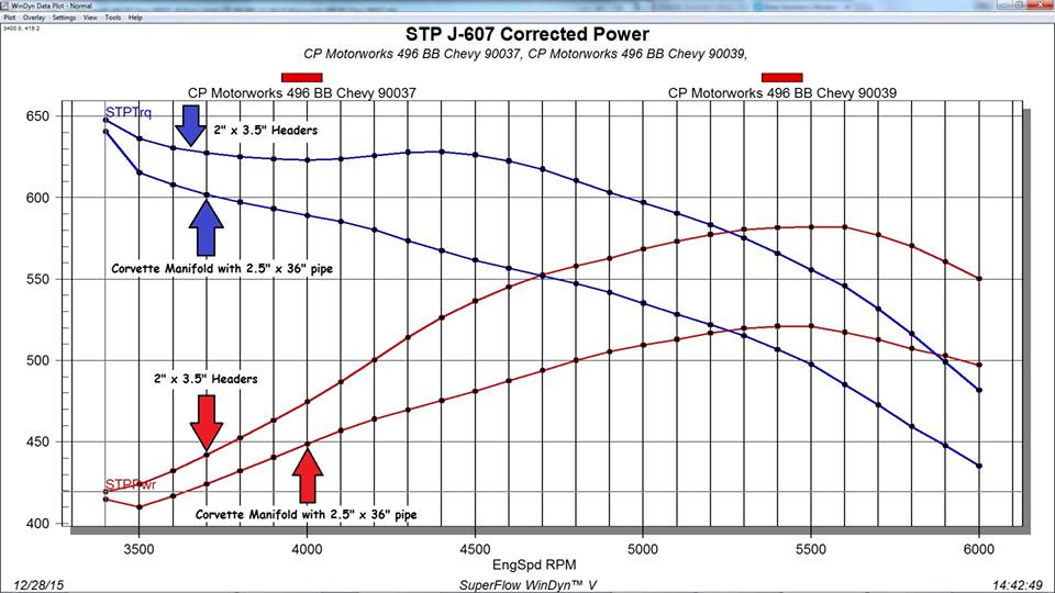
I find this graph very useful, it shows stock corvette exhaust manifolds vs headers on the same 496 BBC engine dyno test
watch the video, and like I stated many times,
its the combo of the engines,
compression,
displacement ,
cam timing
and the exhaust scavenging ,
and the intake manifold design,
NOT the intake port cross sectional area,
that are the most critical factors, in the engines lower rpm and mid rpm torque.
but for damn sure an intake runner port can be small enough to noticeably restrict upper mid range and peak power significantly,
For 5 decades I've heard endlessly about how installing larger free flowing cylinder heads would devastate the engines ability to make any low or mid rpm torque.
especially when Id suggest using a set of smaller 300cc-320cc, aluminum,rectangle port heads on a 496 BBC, or 200 cc-210cc heads on a 406 sbc, I was asked to build
yet on every engine I've ever had built or had some guy ask me to look at, to see why it ran a great deal less impressively than he expected it too,
they brought into my shop its was very obvious (at least to me) that it was the combo of low compression, too little displacement, with too much cam duration ,
a restrictive exhaust or some guy who was trying to save money and continuing to use a stock stall speed torque converter, or retain a badly mis-matched 2.87:1-3.08:1 rear gear ratio,
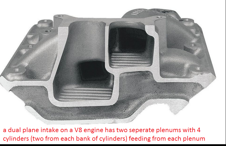
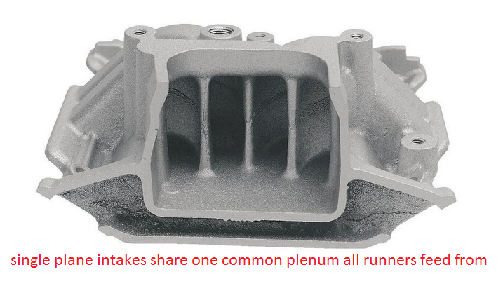
with an engine that he miss matched components by slapping a large carburetor , and a single plane intake on,an engine that will rarely exceed 6000 rpm, that was the major reason.
if you want an engine combo to run your first step is to logically match the list of components you,ll use to the application,
and that requires you stop, engage the brain and think things through carefully,
and the most common way to screw up the process is to over cam a low compression engine,
have a restrictive exhaust or mis-match the drive train gearing to the engines power band.
YOU MIGHT WANT TO READ THIS THREAD.
viewtopic.php?f=56&t=495
the intake side of the cylinder fill efficiency, normally requires the larger valve size because its got lower pressure that the exhaust side of the equation, and the exhaust SCAVENGING helps draw in the following intake charge if its properly timed, to do so.
http://www.carcraft.com/techarticles/cc ... ewall.html
http://www.jegs.com/s/tech-articles/cyl ... Make+Power
viewtopic.php?f=55&t=58&p=36446#p36446
viewtopic.php?f=55&t=10073&p=39779#p39779
http://www.bmw-m.net/techdata/cylinder.htm
http://www.popularhotrodding.com/tech/0 ... ewall.html
viewtopic.php?f=44&t=9525&p=35027&hilit=port+flow+chart#p35027
viewtopic.php?f=52&t=8460&p=32923&hilit=port+flow+chart#p32923
viewtopic.php?f=55&t=8485&p=29767&hilit=port+flow+chart#p29767
viewtopic.php?f=55&t=624&hilit=port+flow+chart
viewtopic.php?f=38&t=1099&p=2215&hilit=+flow+bench#p2215
viewtopic.php?f=52&t=240&p=5334&hilit=cylinder+head+flow+chart#p5334
http://www.purplesagetradingpost.com/su ... eads1.html
http://www.eecis.udel.edu/~davis/z28/winter01/dyno/
http://theamcpages.com/engine-design-va ... -ports.htm
keep in mind its the total combo NOT just the port and runner size alone,
within reasonable limits ,intake port size is one of the least important factors.
your dealing with factors that are interdependent, each change effects the way the other factors respond and interact,
there are ways to predict trends or compensate for changes
change the cam LSA
,duration and lift
engines compression ratio,
intake runner length
header primary diameter and length
and you could very easily find the larger ports made significantly better power.
ID much rather, be faced with a combo where I compensate for a cylinder head with a port size that might be a bit larger than ideal for the application than one thats a bit restrictive to flow, simply because a restrictive port limits upper rpm and peak power far more than a larger port tends to loose low speed responsiveness, because that is much easier to compensate for with changes to the intake, or cam timing or compression, header design etc.
USE THE CALCULATORS, YOULL, QUICKLY FIND THE LIMITATIONS
http://www.rbracing-rsr.com/runnertorquecalc.html
http://www.wallaceracing.com/chokepoint.php
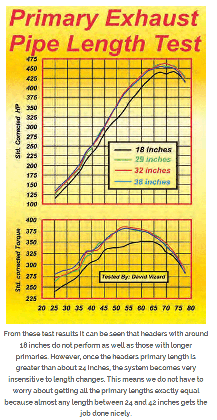
http://www.wallaceracing.com/header_length.php
http://garage.grumpysperformance.co...ing-parts-and-a-logical-plan.7722/#post-49738
http://garage.grumpysperformance.com/index.php?threads/port-speeds-and-area.333/
http://garage.grumpysperformance.co...-the-charts-calculators-and-basic-math.10705/
http://garage.grumpysperformance.com/index.php?threads/carb-intake-test.58/
http://garage.grumpysperformance.co...lsa-effects-your-compression-torque-dcr.1070/
http://garage.grumpysperformance.com/index.php?threads/porting-can-help.462/
http://garage.grumpysperformance.com/index.php?threads/valve-seat-angles-and-air-flow.8460/
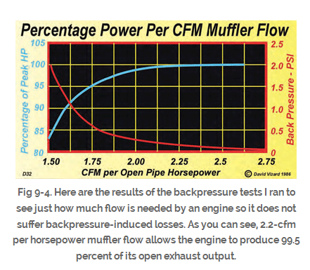
http://garage.grumpysperformance.com/index.php?threads/is-backpressure-hurting-your-combo.495/
http://garage.grumpysperformance.co...spacers-and-related-intake-modification.1038/
http://garage.grumpysperformance.com/index.php?threads/sellecting-cylinder-heads.796/
http://garage.grumpysperformance.co...mbers-or-a-good-street-combo-your-after.5078/
the problem is that intake and exhaust valves open and close several dozen times a second, over most of the engines power band and intake ports see between plus 1psi to minus 30 plus psi which fluctuates rapidly and the exhaust valve sees minus 30 plus psi- a positive 600 psi at different parts of the engines repeated trip thru its 720 degree cycle its rather common to see charts like this one
(I,ll post here below)
showing the flow at each lift , measured at a set lift and constant air flow rate, at every .100, .200,.300,.400,.500,.600 etc. that also list the I/E ratio,
http://users.erols.com/srweiss/tablehdc.htm
the truth here is that larger valves have the potential to flow more gases, but the intake is generally larger because its acted upon by both outside air pressure (14.7 PSI at sea level) and inertial forces the rapidly exiting exhaust flow induces<(EXHAUST SCAVENGING),which can easily exceed the draw the outside air pressure induces by several times
A CORRECTLY TUNED SET OF HEADERS , MATCHED TO A CORRECTLY DESIGNED CAM TIMING HAS A SIGNIFICANT EFFECT ON INTAKE FLOW AND CYLINDER SCAVENGING EFFICIENCY, EXHAUST SCAVENGING CAN BE 5 TIMES STRONGER THAN THE PISTON, MOVEMENT INDUCED NEGATIVE PRESSURE (VACUUM) IN THE INTAKE RUNNERS
but keep in mind the EXHAUST gases are much higher, and once the exhaust valve opens they are PHYSICALLY forced to exit by the piston on the exhaust stroke and the inertia of the rapidly exiting exhaust , from the previous cylinder , tending to drag it out , which both greatly increase efficiency, thus the valve size can be smaller.
youll commonly see intake to exhaust ratios of about 75% on the exhaust to intake flow rates as quoted as ideal, but the truth is , from what Ive seen ,that both cam timing and exhaust primary diameter and length tuning can be used to make most engines run fairly decent at most rpm ranges, and close to ideally over a narrow rpm range.
yes I prefer as high an exhaust to intake ratio as I can get and if I can get a 70%-80% flow rate thats great, especially if your using nitrous, as a power booster, but maintaining that ratio is not critical and in most cases a longer duration on the exhaust cam timing, or changes in the header design can compensate for a less ideal exhaust ratio, if you use a low restriction exhaust behind the headers collector
Junkman2008 said:Hey Grumpy, you always hear that headers give you more horsepower. How does that work and what formula can you use to determine the horsepower gain that a given set of headers may bring?
that questions a bit like asking how good a girl might be in bed based on the color of her hair brush, yes theres a mathematical formula , in fact several, but theres a whole bunch of factors that determine the results, like cam timing, compression,cylinder head flow, back pressure,engine displacement , header primary and collector length and diameter,exhaust temps,etc.
the more back pressure the exhaust system beyond the header collectors has the less effective the headers will be, but if you have a low restriction exhaust and a ram tuned intake with a matched cam timing, a tuned header can in some cases produce gains in excess of 60 hp.
as a general rule Id say your safe expecting a 25-40 hp increase in peak hp from good long tube tuned headers over stock cast iron exhaust manifolds that come on most passenger cars, but with properly matched components on a high compression engine more can be gained.
READ THESE
http://victorylibrary.com/mopar/header-tech-c.htm
http://forum.grumpysperformance.com/viewtopic.php?f=56&t=495&p=613#p613
http://forum.grumpysperformance.com/viewtopic.php?f=56&t=1303
viewtopic.php?f=56&t=572&p=35352&hilit=rams+horn#p35352
http://forum.grumpysperformance.com/viewtopic.php?f=56&t=185
http://www.chevydiy.com/chevy-small-block-engine-guide-exhaust-systems/
I find this graph very useful, it shows stock corvette exhaust manifolds vs headers on the same 496 BBC engine dyno test
its the combo of the engines,
compression,
displacement ,
cam timing
and the exhaust scavenging ,
and the intake manifold design,
NOT the intake port cross sectional area,
that are the most critical factors, in the engines lower rpm and mid rpm torque.
but for damn sure an intake runner port can be small enough to noticeably restrict upper mid range and peak power significantly,
For 5 decades I've heard endlessly about how installing larger free flowing cylinder heads would devastate the engines ability to make any low or mid rpm torque.
especially when Id suggest using a set of smaller 300cc-320cc, aluminum,rectangle port heads on a 496 BBC, or 200 cc-210cc heads on a 406 sbc, I was asked to build
yet on every engine I've ever had built or had some guy ask me to look at, to see why it ran a great deal less impressively than he expected it too,
they brought into my shop its was very obvious (at least to me) that it was the combo of low compression, too little displacement, with too much cam duration ,
a restrictive exhaust or some guy who was trying to save money and continuing to use a stock stall speed torque converter, or retain a badly mis-matched 2.87:1-3.08:1 rear gear ratio,
with an engine that he miss matched components by slapping a large carburetor , and a single plane intake on,an engine that will rarely exceed 6000 rpm, that was the major reason.
if you want an engine combo to run your first step is to logically match the list of components you,ll use to the application,
and that requires you stop, engage the brain and think things through carefully,
and the most common way to screw up the process is to over cam a low compression engine,
have a restrictive exhaust or mis-match the drive train gearing to the engines power band.
YOU MIGHT WANT TO READ THIS THREAD.
viewtopic.php?f=56&t=495
the intake side of the cylinder fill efficiency, normally requires the larger valve size because its got lower pressure that the exhaust side of the equation, and the exhaust SCAVENGING helps draw in the following intake charge if its properly timed, to do so.
http://www.carcraft.com/techarticles/cc ... ewall.html
http://www.jegs.com/s/tech-articles/cyl ... Make+Power
viewtopic.php?f=55&t=58&p=36446#p36446
viewtopic.php?f=55&t=10073&p=39779#p39779
http://www.bmw-m.net/techdata/cylinder.htm
http://www.popularhotrodding.com/tech/0 ... ewall.html
viewtopic.php?f=44&t=9525&p=35027&hilit=port+flow+chart#p35027
viewtopic.php?f=52&t=8460&p=32923&hilit=port+flow+chart#p32923
viewtopic.php?f=55&t=8485&p=29767&hilit=port+flow+chart#p29767
viewtopic.php?f=55&t=624&hilit=port+flow+chart
viewtopic.php?f=38&t=1099&p=2215&hilit=+flow+bench#p2215
viewtopic.php?f=52&t=240&p=5334&hilit=cylinder+head+flow+chart#p5334
http://www.purplesagetradingpost.com/su ... eads1.html
http://www.eecis.udel.edu/~davis/z28/winter01/dyno/
http://theamcpages.com/engine-design-va ... -ports.htm
keep in mind its the total combo NOT just the port and runner size alone,
within reasonable limits ,intake port size is one of the least important factors.
your dealing with factors that are interdependent, each change effects the way the other factors respond and interact,
there are ways to predict trends or compensate for changes
change the cam LSA
,duration and lift
engines compression ratio,
intake runner length
header primary diameter and length
and you could very easily find the larger ports made significantly better power.
ID much rather, be faced with a combo where I compensate for a cylinder head with a port size that might be a bit larger than ideal for the application than one thats a bit restrictive to flow, simply because a restrictive port limits upper rpm and peak power far more than a larger port tends to loose low speed responsiveness, because that is much easier to compensate for with changes to the intake, or cam timing or compression, header design etc.
USE THE CALCULATORS, YOULL, QUICKLY FIND THE LIMITATIONS
http://www.rbracing-rsr.com/runnertorquecalc.html
http://www.wallaceracing.com/chokepoint.php
http://www.wallaceracing.com/header_length.php
http://garage.grumpysperformance.co...ing-parts-and-a-logical-plan.7722/#post-49738
http://garage.grumpysperformance.com/index.php?threads/port-speeds-and-area.333/
http://garage.grumpysperformance.co...-the-charts-calculators-and-basic-math.10705/
http://garage.grumpysperformance.com/index.php?threads/carb-intake-test.58/
http://garage.grumpysperformance.co...lsa-effects-your-compression-torque-dcr.1070/
http://garage.grumpysperformance.com/index.php?threads/porting-can-help.462/
http://garage.grumpysperformance.com/index.php?threads/valve-seat-angles-and-air-flow.8460/
http://garage.grumpysperformance.com/index.php?threads/is-backpressure-hurting-your-combo.495/
http://garage.grumpysperformance.co...spacers-and-related-intake-modification.1038/
http://garage.grumpysperformance.com/index.php?threads/sellecting-cylinder-heads.796/
http://garage.grumpysperformance.co...mbers-or-a-good-street-combo-your-after.5078/
Last edited by a moderator: