READ THIS THREAD ALSO

http://shbox.com/1/component_location_views.html
http://garage.grumpysperformance.co...nvert-gen-i-sbc-to-reverse-flow-cooling.6099/
http://www.chevyhardcore.com/news/r...s-changing-your-small-block-worth-the-effort/
http://garage.grumpysperformance.co...-engine-parts-differences-useful-links.13141/


Ok, maybe some of you will now understand what angles and spacing I am talking about when I say you can and can not do somethings. I didnt have a set of Vortec 350 heads laying around so I used a set of 305 heads which doesnt use the same intake design(actually they are still swirl port junkers) but does use the same bolt pattern.
Pic one, is a Lt1 head, notice that the bolt angle is not flush with the intake face.
Now here is the same head next to a standard SBC head, notice the bolt angle as compared to the SBC gen 1 head, also notice the spacing is different between the two heads. LT1 head is on the left, SBC GEN1 head is on the right. Also notice there is no water jacket on the intake face of the LT1
Here is a SBC GEN1 head next to the LT1 head..This is the deck surface, notice all the water jacket openings are different..SBC Gen1 head is on the left, LT1 on the right
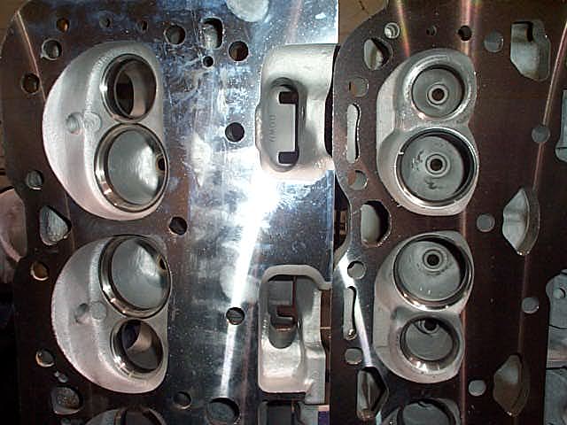
Now there two are for the vortec head, notice that the bolts are even more of an angle than the LT1, when you bolt this intake on, the bolts are facing straight down, also notice there are only 4 bolts per head on the intake, there isnt any bolt holes in the middle
http://www.corvetteactioncenter.com/specs/c4/1996/lt1lt4.html
http://www.grumpysperformance.com/sept2017/lt1vsgen1.jpg
http://www.grumpysperformance.com/april2017/lt1q6a.jpg
http://www.grumpysperformance.com/april2017/lt1q7.jpg
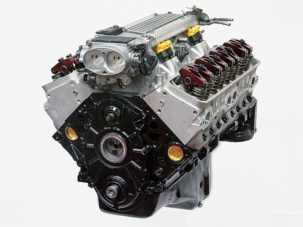
the later GEN2 LT!/LT4 reverse coolant flow block (ABOVE) differs from the first gen SBC
the LT1/LT4 second gen SBC engine was standard in the 1992-1996 corvette
look carefully at the first gen SBC block below
http://garage.grumpysperformance.co...ts-differences-useful-links.13141/#post-68540
http://garage.grumpysperformance.co...ts-differences-useful-links.13141/#post-68540
https://corvetteparts.com/item/engine-cooling-system-rubber-hose-set-lt1-lt4-1995-1996
1995-96 corvette cooling hoses
https://corvetteparts.com/pictures/9EOGbQTvXcqcvnctPS9XwA_3.jpg
http://www.grumpysperformance.com/Mar18/lt1qw1.jpg
[COLOR=#BF0040]http://www.grumpysperformance.com/Mar18/lt1qw2.jpg[/COLOR]
http://www.grumpysperformance.com/Mar18/lt1qw3.jpg
[COLOR=#BF0040]http://www.grumpysperformance.com/Mar18/lt1qw4.jpg[/COLOR]
[IMG]https://corvetteparts.com/pictures/vZWP9szgAxyLpM5PJRVDMA_3.jpg
BTW heres some common LT1 part numbers
Ignition:
1993-1994 optispark (non-vented style, spline driven) 10457702
1995-1997 optispark (vented style, cam dowel driven) 1104032
1995-1997 vented optispark vacuum hoses 12555323
1993-1994 optispark electrical harness 12106559
1995-1997 optispark electrical harness 12130319
1993 ignition coil 1115315
1994-1995 ignition coil 10477208
1996-1997 ignition coil 10489421
1993 ignition control module 10483131
1994-1995 ignition control module 10483139
1996-1997 ignition control module 10482803
Camshaft/Valvetrain LT4 valve springs (set of 16) 12495494
LT4 Valve spring (1) 12551483
LT4 extreme duty timing set 12370835
LT4 Hotcam
(CRANE CAMS USED TO SUPPLY MANY G.M.PERFORMANCE CAMS,
this is no longer true and QUALITY has dropped off noticeably by who ever is currently supplying the cams)
LT4 1.6 roller rocker arm (1) 12557779
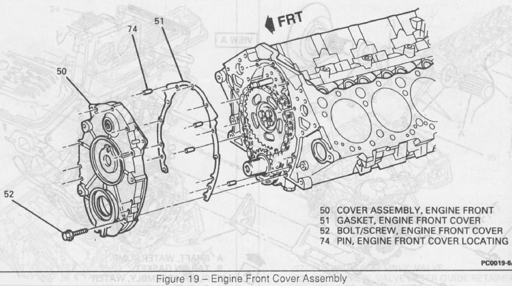
1993-1994 front cover (includes round seals) 12551636
1995 front cover (includes round seals) 12552426
1996-1997 front cover (includes round seals) 12552427
1993-1994 front cover opti seal 10128317
1995-1997 front cover opti seal 12552428
1993-1997 front cover crank seal 10128316
1993-1997 front cover water pump seal 10217886
1993-1997 front cover gasket 10128293
General Engine:
LT4 heads 12555332
LT4 Intake Manifold 12550630
Misc
F-body a/c delete pulley 10115875
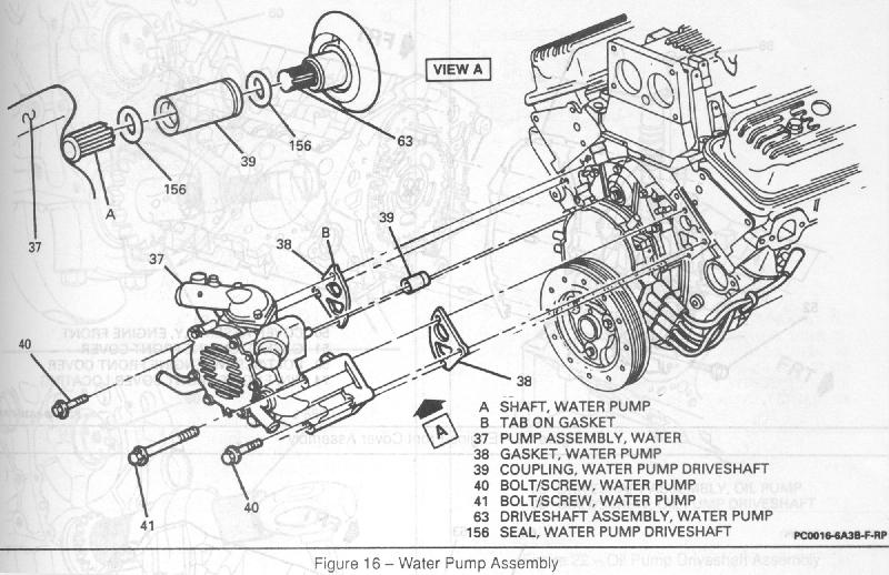
1993-1997 water pump 12527741
1993-1997 water pump coupling 10128334
1993-1994 1LE intake elbow (no vent hole for opti) 25147210
1995-1997 1LE intake elbow (for vented opti) 25147187
1994-1997 front flexible fuel supply lines 10258441
PCM Related
1993-1995 knock sensor 10456126
1996-1997 knock sensor 10456287
LT1 Knock Module 94-95 OBD1 16217700
LT1 Knock Module 96-97 OBD2 16214661
LT4 Knock Module 96-97 OBD2 16214681
Head Gasket Thickness
Stock gasket = 0.040
Fel Pro 1074 = 0.039
Impala = 0.029
Mr Gasket 5716 = 0.026
12561388 Main Bearing Cap Bolt Outer 10
3877669 Main Bearing Cap Bolt Inner 6
12561389 Main Bearing Cap Stud Inner 3
9442946 Main Bearing Cap Nut For Windage Tray 1
12453170 Camshaft Bearing—Camshaft #1 1
12453171 Camshaft Bearing—Camshaft #2 1
12453172 Camshaft Bearing—Camshaft #3, 4 2
10241154 Camshaft Plug—Rear 1
88891749 Freeze Plug, Cup—Brass 41.1mm 8
10120990 Main Bearing (Std) #1, 2, 3, 4 (All Small Blocks Except 383) 4
10120993 Main Bearing (Std) Rear (All Small Blocks Except 383) 1
1453658 Transmission Dowel Pin 5/8″ X 1 3/16″ 2
12554553 Front Dowelpin 1/4″ X 5/8″ 2
585927 Dowel Pin 5/16″ X 9/16″ 4
14081701 1/4″ Pipe Plug (Thread Socket Head) 4
14091563 Oil Galley, Steel Cup Plug (.476″) 4
9441003 Rear Seal Housing Locator Pin 7/16″ X 9/16″ 1
14084945 Block Drain Plug (1/4-18 X .56) Threaded 2
14088556 Rear Seal Retainer 1
10088158 Rear Crank Seal 1-Pc Style 1
14080362 Oil Pan Stud—Outboard 1
12555771 Rear Adapter Gasket to Block 1
14101058 Adapter Stud 2
14088561 Adapter Bolt—Torx Upper 1
9439915 Hex Nut, Adapter To Stud 1/4-20 X .234 1
14088562 Adapter Bolt, Torx Thru Loc Pin 1/4-20 X .75
10121044 Rear Seal (2-Piece Seal Design) 1
12513961 Front Cover, Sheet Metal With Welded Pointer 1
10108435 Front Cover Gasket—Sheet Metal Cover 1
10243247 Front Crank Seal—Sheet Metal Cover 1
12562818 Cover, Engine Front w/o Pointer ZZ4 Design Engines 1
10228655 Front Crank Seal 1
9439930 Front Cover Bolt 10
10213293 Front Cover Bolt 6
12551135 Front Cover Bolt 2
10213294 Eng Frt Cover Bolt Grommet 8
14090911 Plug (3/8-18 Threaded) ar
10168527 Head Bolt—Short 4
10168526 Head Head—Medium 20
10168525 Head Head—Long 4
10089648 Rocker Arm—w/Nut & Ball (Use With All Steel Rockers) ar
10088128 Camamsft Retainer 1st Des 3.620 Bolt Pattern 1
10168501 Camshaft Retainer 2nd Des 3.294 Bolt Pattern 1
14093637 Camshaft Bolt Retainer (Torx) 2
12554553 Camshaft Sprocket Locator Pin To Cam 1/4 X 5/8 1
9424877 Camshaft Bolt Sprocket 5/16-18 X 3/4 300m 3
10108688 Connecting Rod—All Except 383 Engines ar
461372 Connecting Rod Bolt—All Except 383 Engines ar
225854 Connecting Rod Nut—All Except 383 Engines ar
12523924 Connecting Rod Bearing (Std) Except 383 Engine ar
10046031 Flywheel Locator Pin 7/16 X 7/8 1
14061685 Clutch Pilot Bearing All With Manual Trans. 1
106751 Damper Key—Front Of Crankshaft (Woodruff) 1
3754587 Water Pump Gasket 2
9442012 Water Pump Bolts 3/8-16/ 2 1/4 4
14088753 Water Outlet 1
10198997 Water Outlet Bolts 2
10105135 Water Outlet Gasket 1
10207373 Thermostat, 195 Deg 1
10202456 Thermostat, 180 Deg 1
10108676 Oil Pan Gasket (1-Pc Des) 1
11518377 Oil Pan Drain Plug 12mm 1
3536966 Oil Pan Drain Plug O-ring Seal 1
3921988 Oil Pan Drain Plug, 1/2 1
14090908 Oil Pan Drain Plug Gasket 1
12553058 Oil Pan Reinforcement LH 1
12553059 Oil Pan Reinforcement RH 1
9440033 Oil Pan Bolt 1/4-20 X 5/8 14
12338130 Oil Pan Nut 5/16-18 2
9424877 Oil Pan Bolt 5/16-18 X 3/4 2
12551154 Oil Tube Indicator 1
12551144 Oil Tube Indicator 1
3952301 Oil Filter Adapter w/Bypass Valve
3951644 Oil Filter Adapter Bolt 5/16-18 X 1 1/8 2
3764554 Oil Pump Shaft Retainer (Nylon) 1
12525810 Intake Manifold Gaskert Set (For ZZ4 Engines) 1
89017465 Intake Manifold Gasket (For Vortec Design Heads) 1
12550027 Bolt, Intake Manifold (All With Vortec Design Heads) 8
88891769 Bolt, Intake (3/8-16 X 1 1/2 ) ZZ4 Design Engines 4
14091544 Bolt, Intake (3/8-16 X 1 1/8 ) ZZ4 Design Engines 4
9439918 Bolt, Intake (3/8-16 X 1 3/8 ) ZZ4 Design Engines 4
6269414 Manifold, Egr Cover, ZZ4 Engine 1
12554530 EGR Gasket ZZ4 Engine 1
9442184 EGR Cover Bolt T/w 9439571 Washer 2
14094792 Manifold, Choke Cover ZZ4 Engine 1
14096848 Manifold Choke Cover Gasket ZZ4 Engine 1
14094069 Fuel Pump Block Off Plate 1
12560223 Fuel Pump Cover Gasket 1
3719599 Fuel Pump Adapter Plate 1
9440033 Bolts, Fuel Pump 1/4-20 X 5/8 2
9442963 Bolts, Fuel Pump 3/8-16 X .3/4 2
3704817 Fuel Pump Push Rod 1
Last edited: Jun 10, 2017
more info
http://www.nookandtranny.com/Info_LT1.html
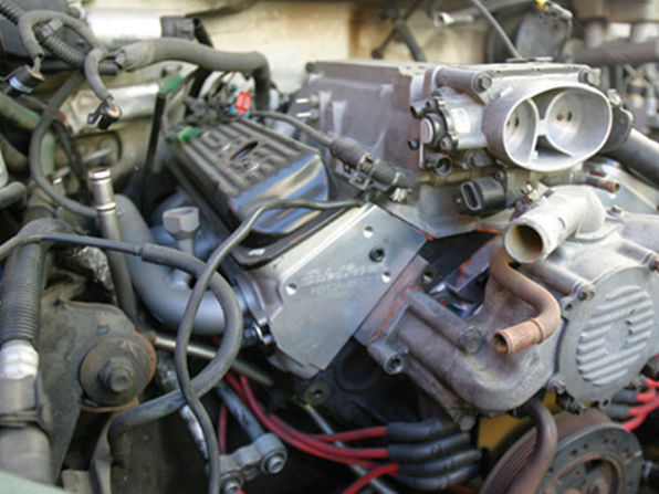
lt1 cylinder heads don,t flow coolant thru the intake to the radiator like the earlier heads do, the water pump is the exit point for coolant flow.
the lt1 heads will bolt on, too a standard sbc block, coolant passages are not an exact match, and theres no coolant ports in the LT1 heads too feed coolant too the intake manifold and radiator
theres no coolant flowing through the LT1/LT4 intake manifold, so you can,t bolt the standard SBC intake too the LT1 heads and get coolant flow back too the radiator, you can,t bolt an LT1 water pump too an earlier first gen SBC as the block and way the pump is driven is totally different, the LT1 water pump is driven bye a camshaft splined drive
http://www.enginebuildermag.com/1999/09/rebuilding-the-chevrolet-lt1-engine-2/
http://garage.grumpysperformance.com/index.php?threads/lt1-cooling-info.2538/
LT1 HEADS
theres no coolant flowing through the LT1/LT4 intake manifold, so you can,t bolt the standard SBC intake too the heads and get coolant flow back too the radiator, the LT1 water pump is driven bye a camshaft splined drive
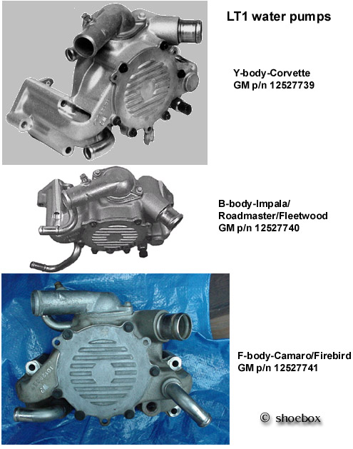
LT1 water pump
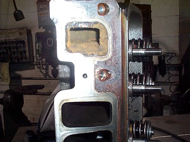
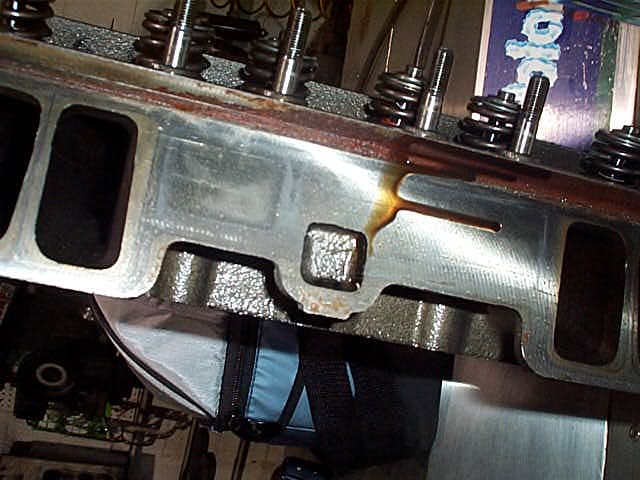
NOTICE THE STANDARD DESIGN HEADS HAVE WATER to INTAKE TRANSFER PORTS

INFO BELOW FROM
http://www.indipalass.com/ARCHIVE/TechC ... System.htm
http://automotivemileposts.com/autobrev ... ecoil.html
"LT1 Reverse Flow Cooling System
By Scott Mueller.
One of the greatest features of the '92 and up Chevrolet LT1 engine is the reverse flow cooling system. In fact it is reverse flow cooling that is truly the key to the incredible performance of the modern LT1. Reverse flow cooling is vastly superior to the conventional cooling systems used on virtually all other engines. This is because it cools the cylinder heads first, preventing detonation and allowing for a much higher compression ratio and more spark advance on a given grade of gasoline. A fringe benefit is that cylinder bore temperatures are higher and more uniform, which reduces piston ring friction. Because of this new cooling system, the LT1 can easily meet ever increasing emissions standards with significant gains in power, durability, and reliability.
Conventional Coolant Flow:
In a conventional engine design, coolant enters the front of the block and circulates through the block's water jacket. The coolant is first heated by the cylinder barrels, and then hot coolant is subsequently routed through the cylinder heads and intake manifold before returning through the thermostat to the radiator.
Because the coolant from the radiator is first directed to the cylinder bores, they run at below optimum temperatures which increases piston ring friction. The heads subsequently get coolant that has already been heated by the cylinder block, which causes the heads to run well above optimum temperatures. The hotter cylinder heads promote detonation (spark knock) and head gasket failures. To combat the increased tendency to detonate, compression ratios has to be lowered and spark advance reduced, which significantly reduces engine power output and efficiency.
Besides promoting detonation, causing gasket failures, forcing reduced compression, spark advance, and significantly reduced power output, a conventional cooling system causes several other problems. Since the thermostat is on the exit side of the system, it does not have direct control over the cold coolant entering from the radiator. This is especially true when the thermostat first opens after reaching operating temperature. As the thermostat first opens allowing hot coolant to exit the engine, a rush of very cold coolant enters the block all at once, shocking the engine and causing sudden dimensional changes in the metal components. The extreme thermal shock experienced by the engine causes head gaskets and other soft parts to fail much more quickly.
Conventional cooling system design also allows isolated engine hot spots to occur, which lead to the generation of steam pockets and coolant foaming. Coolant which is full of air and foam reduces cooling system performance and can even lead to engine overheating.
LT1 Coolant Flow:
The LT1 is completely different since it uses reverse flow cooling. The incoming coolant first encounters the thermostat, which now acts both on the inlet and outlet sides of the system. Depending on the engine coolant temperature, cold coolant from the radiator is carefully metered into the engine. This allows a more controlled amount of cold coolant to enter, which immediately mixes with the bypass coolant already flowing. This virtually eliminates the thermal shock present in the old system.
After entering through one side of the 2-way thermostat (at the appropriate temperature), the cold coolant is routed directly to the cylinder heads first, where the combustion chambers, spark plugs and exhaust ports are cooled. Then the heated coolant returns to the engine block and circulates around the cylinder barrels. The hot coolant from the block re-enters the water pump, and hits the other side of the 2-way thermostat, where it is either re-circulated back through the engine or directed to the radiator, depending on temperature.
The main concept behind reverse flow cooling is to cool the heads first, which greatly reduces the tendency for detonation, and is the primary reason that the LT1 can run 10.5 to 1 compression and fairly significant ignition advance on modern lead-free gasoline. Reverse flow cooling is THE KEY to the Generation II LT1s increased power, durability, and reliability over the first generation smallblock engine.
Thermostats:
All LT1 engines utilize a special 2-way acting full bypass thermostat. This means that the thermostat regulates coolant flow both in to as well as out of the engine, while the bypass portion of the thermostat circuit supplies the water pump with a full flow of liquid coolant at all times. This is unlike a conventional engine thermostat, which only regulates coolant flow at the engine outlet, and which does not allow full flow through the water pump when the engine is cold and the thermostat is in bypass mode.
Both sides of the 2-way thermostat used in the LT1 are linked together, and a single wax pellet actuator operates the spring loaded mechanism at a pre-set temperature. When the designated temperature is reached, the wax pellet expands, opening the dual acting valve. All current LT1s come from the factory with a relatively low 180 degree temperature thermostat. Most conventional engines today use 195 degree thermostats in order to meet emissions specifications at the expense of power, durability, and reliability.
It is important to note that the 2-way thermostat is unique to the Generation II LT1 and is not interchangeable with older Chevrolet smallblock engines. This is particularly important if you decide to change to a colder 160 degree thermostat, make sure it is the proper dual acting type required by the modern LT1.
Additional LT1 Cooling System Improvements:
In addition to reverse coolant flow, there are several other improvements in the LT1 cooling system over conventional engines.
Dry Intake Manifold:
The LT1 has absolutely NO water running through the intake manifold! Conventional cooling systems have passages in the intake manifold which allow coolant to crossover from one side of the engine to the other. In the LT1, coolant crossover occurs in the water pump, which is also where the thermostat is located. Since there are no coolant passages in the intake manifold, a major source of leaks has been eliminated. Overall engine reliability is improved since an intake manifold leak allows coolant to enter the top of the engine which can quickly wipe out the camshaft, lifters, and other major engine components. Designing a dry intake manifold without either coolant passages or a thermostat housing also allows a much lower profile. The LT1 engine is 87mm (nearly 3.5 inches) lower than the previous L98 Corvette engine.
Gear Driven Water Pump:
One big problem with conventional cooling systems is the water pump, which simply cannot last a targeted minimum 100,000 mile reliability figure without experiencing leaking gaskets or seal failures. This has traditionally been caused by the excessive side loads placed on the bearings and seals of a conventional water pump through the belt drive mechanism. In the LT1 this problem is solved by driving the water pump directly via a spur gear driven by the camshaft sprocket. This results in a dramatically more reliable water pump that should easily last 100,000 miles or more.
Since the water pump is no longer belt driven, the vehicle will still be driveable even if the serpentine belt fails. This is a major safety factor as it allows one to drive the partially disabled vehicle to the nearest service center.
Steam Vents:
The LT1 has strategically placed steam vents at the back of both cylinder heads. Since the heads are the hottest part of the engine, pockets of steam can be more easily generated there. The steam vents are connected together by a crossover vent tube at the back of the heads, which directs any steam and a small flow of coolant to the front of the engine where it flows through the throttle body, warming it for improved cold weather performance. After passing through the throttle body, most of the steam is condensed back into liquid coolant and returned to the system.
In LT1 B/D-cars, coolant exiting the throttle body is passed directly into a pressurized coolant reservoir where any air remaining in the coolant is completely scavenged. In LT1 F-cars, coolant from the throttle body connects to the heater outlet via a vented "tee" connector, where any trapped air in the system can be bled off manually. Eliminating steam pockets and foam in the coolant allows for more uniform cooling system performance, preventing hot spots and potential overheating.
Reverse Flow Radiator:
Unlike a conventional cooling system, the thermostat coolant outlet is connected to the bottom of the radiator. This forces the coolant entering the radiator to push up through the radiator core and eventually emerge through the top radiator coolant outlet. This helps to eliminate air pockets in the radiator, and provides a more even distribution of cooling through the core and improving radiator efficiency.
Precision Machined Thermostat Housing:
The thermostat housing is a precision machined component that fits directly onto the top of the water pump without a gasket. Instead, an O-ring is used to seal the thermostat inside the housing. This precision design reduces the tendency for leaks, plus it makes thermostat replacement a very simple job since there is no old gasket material to scrape off. Servicing is further simplified because the thermostat housing is situated directly on top of the water pump, and access is unobstructed. I dare say that the LT1 thermostat is the easiest to change I have ever experienced. Finally, an air bleeder valve is located on the top of the thermostat housing, which allows one to quickly and easily bleed out any trapped air after cooling system maintenance has been performed.
Low Operating Pressure:
The entire cooling system on the LT1 is designed to operate at lower pressures than conventional cooling systems. The maximum operating pressure in the LT1 cooling system is 15 psi for B/D-cars and 18 psi for F-cars, limited by a pressure cap. These limits are similar to other cars, but in the LT1, these maximum pressures are rarely reached. Running at a lower pressure drastically decreases the number of leaks and significantly improves overall reliability and durability.
Coolant Reservoir:
Corvette and B/D-car LT1 applications use a pressurized coolant recovery reservoir instead of a non-pressurized overflow tank used with conventional cooling systems. All of the coolant flows continuously through the pressurized reservoir, which is an integral part of the cooling system. The pressurized reservoir in the LT1 B/D-cars is connected to the cooling system in three places. One inlet hose connects to the top of the RH radiator tank, a second inlet hose is attached through a "tee" connection on the heater inlet hose, and a third outlet hose is connected to a "tee" connection in the throttle body heater outlet.
The pressurized reservoir is mounted at the highest point in the system, and provides a place where all air can be continuously scavenged from the coolant. Any steam and bubbles are allowed to rise to the surface, eliminating foam and providing pure liquid coolant back to the engine. Pure liquid coolant is returned to the system via the heater outlet hose connection. The pressure relief/vent cap in these systems is rated at 15 psi and is located on the reservoir rather than the radiator.
LT1 F-cars use a conventional coolant recovery system which consists of a non-pressurized coolant overflow tank connected to the radiator by a single hose. These cars use an 18 psi rated pressure relief/vent cap on the radiator like most conventional systems. Since these cars cannot scavenge air from the coolant as well as the B/D-car or Corvette systems, they have two air bleeder valves for manually bleeding trapped air from the system. One is in the thermostat housing, which is the same as all other LT1 engine vehicles, and the second one is located in a "tee" where the coolant from the throttle body connects to the heater return hose.
B/D-car LT1 (Caprice/Impala/Roadmaster/Fleetwood) Cooling Systems:
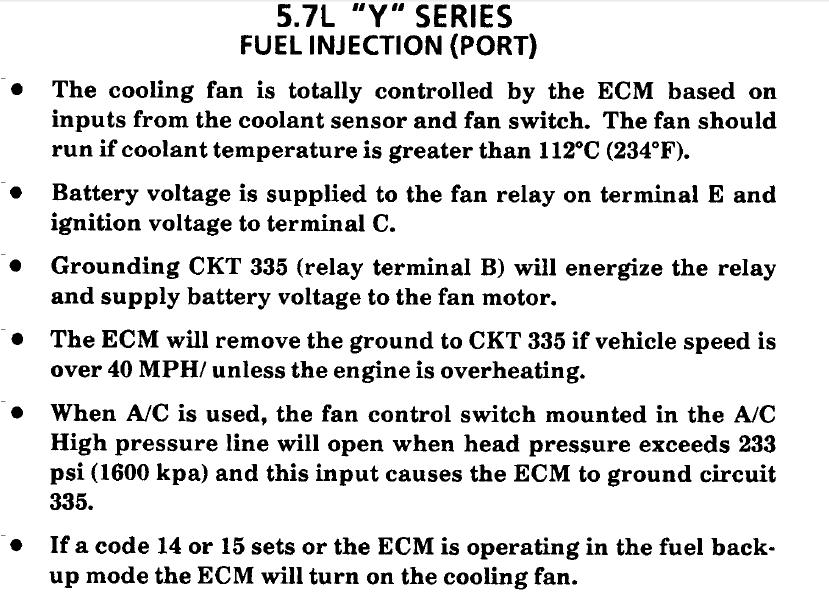
Standard equipment for all LT1 equipped B/D-cars is a dual electric fan setup with a 150-watt primary (RH) fan and a 100-watt secondary (LH) fan. The electric engine coolant fans are independently operated by the PCM (Powertrain Control Module) based on the inputs from the Engine Coolant Temperature (ECT) sensor, A/C Pressure Sensor, Vehicle Speed Sensor (VSS), and various other inputs.
The B/D-car coolant fans operate under PCM control at the following engine temperatures and A/C system pressures:
Fan Mode
Temperature A/C Pressure
Primary (RH) Fan ON 107 C 225 F 189 psi
Primary (RH) Fan OFF 103 C 217 F 150 psi
Secondary (LH) Fan ON 111 C 232 F 240 psi
Secondary (LH) Fan OFF 107 C 225 F 210 psi
Additionally, the PCM will turn off the fans at higher vehicle speeds (above 48 MPH I believe) since running fans can actually impede airflow through the radiator at high
speed. Each fan also has a minimum running time. Once activated, the primary fan will run for a minimum of 50 seconds, and the secondary fan for a minimum of 26
seconds. Finally, certain Diagnostic Trouble Codes (DTCs) may cause the PCM to turn on one or both fans.
All LT1 B/D-cars have two transmission oil coolers and an engine oil cooler as standard equipment. The transmission coolers include a primary oil to water type inside the RH radiator tank, and a secondary external oil to air cooler (KD1) mounted in front of the radiator on the RH side. The external KD1 cooler is an aluminum stacked plate type cooler painted black with metal tube lines linking it in series with the other cooler in the radiator tank. LT1 B/D-cars also include an engine oil to water cooler (KC4) mounted in the LH radiator tank.
Optional B/D-car LT1 Cooling Systems:
There are two optional cooling system upgrades for LT1 B/D-cars, called V03 (Extra Capacity Cooling), and V08 (Heavy Duty Cooling). Performance models such as the WX3 (Impala SS) and 9C1 (Police) cars automatically get the upgraded V03 (Extra Capacity Cooling) system. V03 includes a larger radiator, an increased capacity A/C condenser, and an upgraded secondary electric fan. V03 is also optional on most B/D-car models.
Note that the '94 V03 (Extra Capacity Cooling) option uses a 150-watt primary (RH) fan, and an upgraded 240-watt secondary (LH) fan. In '95-'96 the V03 package was revised and no longer included an upgraded 240-watt secondary fan. Instead the standard 100-watt secondary fan was used, which is the same as the base cooling system.
B/D-cars other than the Impala SS or Police package Caprice also have an optional V08 (Heavy Duty Cooling) package which is part of the V92 (Trailer Towing) package. V08 includes the larger radiator, increased capacity A/C condenser, and upgraded secondary fan as in the V03 system, however it differs in the primary cooling fan. With V08 the 150-watt electric primary fan is replaced by a mechanical belt driven thermostatic clutch fan. To drive the mechanical fan, the V08 system includes a crank pulley, belt tensioner and bracket, and a large radiator shroud in addition to the mechanical fan itself. This package is not available on the WX3 (Impala SS) or 9C1 (Police) cars since the mechanical fan is driven by an additional pulley and belt on the engine crankshaft, which draws engine power thus reducing performance.
The mechanical fan used with the V08 cooling system contains a built-in thermostatic clutch which senses the temperature of air that has been drawn through the radiator. When the temperature of this air is below 66 degrees C (151 degrees F), the clutch freewheels and limits the fan speed to 800-1,400 rpm. When the temperature rises above 66 degrees C (151 degrees F), the clutch begins to engage, and the fan speed increases to about 2,200 rpm. The RH radiator hose in V08 equipped vehicles has a steel tube section near the fan designed to prevent damage in case of fan contact.
There are several SEO (Special Equipment Option) B-car cooling options which are included as standard only with 9C1 (Police) package Caprices. These include the following:
In addition to the standard inclusion of the V03 (Extra Capacity Cooling) package, all LT1 Caprice 9C1 (Police) cars also include SEO 1T1 (Silicone Radiator and Heater Hoses). SEO 1T1 consists of special green radiator and heater hoses made out of pure silicone rubber. These hoses are designed to last the life of the vehicle and never need replacement unlike the standard black rubber hoses. SEO 1T1 also includes heavy duty stainless steel worm gear hose clamps which replace the standard squeeze type hose clamps. The clamps have a solid full perimeter band, which prevents the hose from extruding between the slotted area where the screw fits. This also prevents the hose from being cut or damaged by the clamp, and allows a more even sealing force around the entire clamp perimeter.
The 9C1 Police package also includes SEO 7P8 (External Engine Oil to Air Cooler). This is an unpainted aluminum stacked plate type cooler which is mounted in front of the radiator on the LH side opposite the external transmission cooler. This heavy duty engine oil cooler replaces the standard engine oil to water cooler found in the LH radiator tank of other LT1 B-cars.
Also included with the Police package is SEO 7L9 (Power Steering Fluid Cooler). This consists of a loop of metal tubing installed between the radiator lower support and the front stabilizer bar. This cooler prevents the power steering fluid from overheating in rigorous driving situations such as high speed persuit.
F-car LT1 (Camaro/Firebird) Cooling Systems:
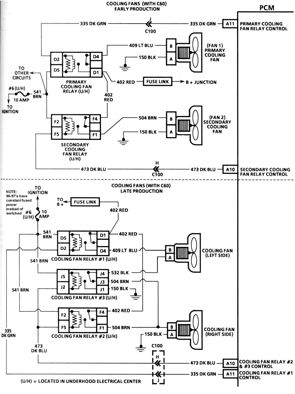
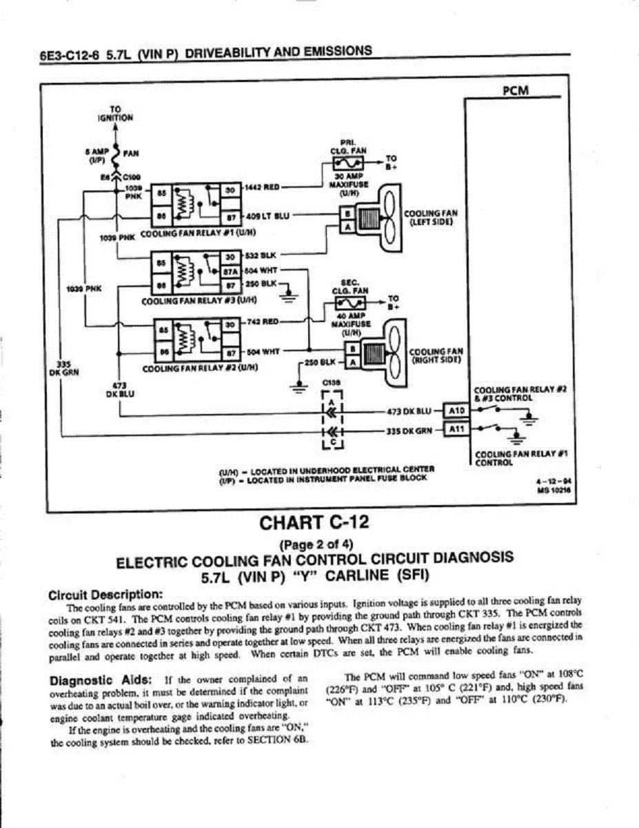
Standard equipment for all LT1 F-cars with A/C is a dual electric fan setup with primary (LH) and secondary (RH) fans. There are two different wiring schemes used for these fans, an early design that was used in '93-'94 and a late design that has been used from mid-'94 up. Note that non-A/C F-cars have a single primary fan which operates at a fixed high speed.
In '93 and early '94 models with A/C, the two cooling fans are independently operated by the PCM (Powertrain Control Module) at a high fixed speed by using a single relay for each fan. Late '94 and newer F-car models operate both fans simultaneously in either a low or a high speed mode by using 3 relays. In low speed mode, the fans are powered in series. In high speed mode, the relays operate to power both fans in parallel, resulting in a higher speed of operation.
One way to tell which setup you have is by looking at the alternator. If an F-car is equipped with the 124 amp alternator (KG7), then the vehicle has the early design setup and the fans are operated independently. If the vehicle has the 140 amp alternator (KG9), then it also has the newer design configuration which operates the fans simultaneously in low or high speed modes.
The PCM operates the coolant fans based on input from the Engine Coolant Temperature (ECT) sensor, A/C Pressure Sensor, Vehicle Speed Sensor (VSS), and various other inputs. The F-car coolant fans operate at the following temperatures and pressures:
Fan Mode
Temperature A/C Pressure
Primary (LH) or Dual Low-speed Fan(s) ON: 108 C 226 F 248 psi*
Primary (LH) or Dual Low-speed Fan(s) OFF: 105 C 221 F 208 psi*
Secondary (RH) or Dual High-speed Fan(s) ON 113 C 235 F 248 psi
Secondary (RH) or Dual High-speed Fan(s) OFF: 110 C 230 F 208 ps
*Note - this information is probably incorrect, although it is quoted from the service manual.
Additionally, the PCM will turn off the fans at higher vehicle speeds (above 70 MPH I believe) since running fans can actually impede airflow through the radiator at high speed. Each fan or fan mode has a minimum running time. Once activated, the primary fan or dual low-speed fans will run for a minimum of 50 seconds, and the secondary or dual high-speed fans for a minimum of 30 seconds. Finally, certain Diagnostic Trouble Codes (DTCs) may cause the PCM to turn on one or both fans.
All LT1 F-cars with automatic transmissions also have a transmission oil cooler as standard equipment. The transmission cooler is an oil to water type mounted inside the RH radiator tank.
Optional F-car LT1 Cooling Systems:
There is only one option in an LT1 F-car with respect to cooling, and that is an engine oil cooler (KC4). The engine oil cooler is an oil to water design that is mounted in the LH radiator tank. The KC4 oil cooler is included with various other combinations of options on the F-cars.
Operating Characteristics and Observations:
I have an accurate digital temperature gauge installed in the RH cylinder head water jacket on my '94 Impala SS. I installed a brass "T" fitting in the RH cylinder head, in the tapped hole where the factory temperature gauge sender was originally installed. This allowed me to install both the original analog gauge sender as well as the sender for the new digital gauge. With the stock 180 degree thermostat, cruising at 80 mph on a cool night I would routinely measure coolant temperatures in the head as low as 167 degrees! If I slowed down, the temperature would climb up into the 170-180 degree range depending on ambient temperatures and cruising speed. The temperature would run in the 180s-190s cruising more slowly on a hot summer day. In heavy stop and go traffic, the temperature would quickly climb up into the 220-230 degree area, which is where the primary fan starts to come on.
Many have noticed as I have that the engine will actually run cooler in traffic with the A/C on. This is because turning on the A/C will also cause the PCM to activate at least the primary fan, and possibly the secondary fan (depending on A/C system pressure) as well.
The radiator and A/C condenser in B/D-cars equipped with the RPO (Regular Production Option) V08 (Heavy Duty Cooling) or V03 (Extra Capacity Cooling) systems are extremely large, perhaps the largest of any passenger car on the market today. The cooling and A/C system performance on these cars are outstanding, in fact the best I have seen on any vehicle.
Recommendations for Cooling System improvements:
If you have a B/D-car, there are several easy improvements you can make by simply adding the cooling related SEOs (Special Equipment Options) from the 9C1 Caprice Police package. For example, I have installed all of the Police package cooling upgrades in my '94 Impala SS. This includes the 1T1 silicone hoses, 7L9 power steering fluid cooler, and 7P8 external engine oil cooler. Combined with the already powerful V03 cooling system, these factory upgrades combine to form the most extreme duty factory cooling system present on any automobile I have seen.
If you have an F-car which was not factory equipped with the optional KC4 engine oil cooler, then I would highly recommend installing it as an upgrade. The KC4 option consists of a different radiator with the engine oil cooler located inside the LH tank. An adapter installs on the oil filter pad between the filter and the engine, and lines run to the cooler in the radiator tank.
There are two other cooling system improvements that can be applied to any vehicles with the LT1 engine, including the Corvette and F-cars (Camaro/Firebird). These are to change to a colder 160 degree thermostat (180 is standard), and to alter the electric cooling fans to come on at a lower temperature. This latter function can be accomplished by adding an external thermostatic switch to the fan circuit, or by re-programming the PCM fan operation settings.
As mentioned earlier in this article, the stock fans do not come on until at least 225 degrees, which I feel is too hot. To prevent the engine from heating up this high in traffic or while moving slowly, I installed a 203 degree GM thermostatic switch (p/n 3053190) in a pre-existing tapped hole in the LH cylinder head water jacket, and wired it to both the primary and secondary fan relay via a 3-position toggle switch.
When the coolant temperature reaches 203 degrees, the primary or secondary fan (depending on the setting of the toggle switch) will run. This prevents the engine from running hotter than about 200 degrees or so. I have tested this modification in 100 degree ambient temperatures, while trapped in stop and go traffic, and never saw coolant temperatures higher than 205 degrees. I wired the toggle switch to operate either the primary or secondary fan, as well as to disconnect the thermostatic switch from the circuit, thus disabling this function. No matter what the toggle switch setting, the PCM still has control over the fan relays, and will continue to operate the fans oblivious to the additional thermostatic switch function.
I have more recently purchased the Hypertech Power Programmer, which re-programs the PCM to turn the primary fan on at 176 degrees (instead of 225), and the secondary fan on at 191 (instead of 232). At first I installed the Hypertech program without the recommended 160 degree thermostat in order to observe the operation of the fans. I found that the primary fan would run continuously once the engine had warmed up, and even the secondary fan would be on most of the time. This is due to the overlap between the high thermostat setting and the lower fan activation temperatures programmed in by Hypertech. The new settings were turning the primary fan on at a setting lower than the thermostat itself would open.
After installing the recommended 160 degree thermostat, the fans worked normally, and would only begin to run after the car was not moving which allowed the temperature to rise. In actual operation I saw temperatures while moving about 10 degrees lower than what I observed with the 180 degree thermostat. While moving very slowly or sitting stationery, the engine would never climb above the low 190 range, no matter how high the ambient temperatures was or how slow I was moving. After observing this operation, I would wholeheartedly recommend the 160 degree thermostat and the Hypertech Power Programmer. If you use the Power Programmer, then the 160 degree thermostat MUST be installed or the fans will run continuously, which is not good for either the fans, alternator, or battery.
If you do not want to purchase the (fairly expensive) Power Programmer, then I highly recommend installing the 203 degree thermostatic fan switch I listed, which will prevent the excessive temperatures encountered in traffic that are allowed by the stock PCM program settings. The fan switch will work well with either the stock 180 degree thermostat or a 160 degree unit, and will limit the maximum coolant temperatures to 205 degrees or less.
GM Vehicles Featuring the Generation II LT1:
Chassis Models Years
Y-car Corvette '92-'96
F-car Camaro/Firebird '93-'96
B-car Caprice/Impala/Roadmaster 94-'96
D-car Fleetwood '94-'96"
http://shbox.com/1/component_location_views.html
http://garage.grumpysperformance.co...nvert-gen-i-sbc-to-reverse-flow-cooling.6099/
http://www.chevyhardcore.com/news/r...s-changing-your-small-block-worth-the-effort/
http://garage.grumpysperformance.co...-engine-parts-differences-useful-links.13141/
I found this a bit interesting
https://garage.grumpysperformance.com/index.php?threads/lt1-lt4-1992-96-corvette-engine-related.14574/#post-112095 https://garage.grumpysperformance.com/index.php?threads/curing-that-problem-with-how-your-c4-corvette-runs-badly-or-wont-start.15212/#post-105777...
garage.grumpysperformance.com
Ok, maybe some of you will now understand what angles and spacing I am talking about when I say you can and can not do somethings. I didnt have a set of Vortec 350 heads laying around so I used a set of 305 heads which doesnt use the same intake design(actually they are still swirl port junkers) but does use the same bolt pattern.
Pic one, is a Lt1 head, notice that the bolt angle is not flush with the intake face.
Now here is the same head next to a standard SBC head, notice the bolt angle as compared to the SBC gen 1 head, also notice the spacing is different between the two heads. LT1 head is on the left, SBC GEN1 head is on the right. Also notice there is no water jacket on the intake face of the LT1
Here is a SBC GEN1 head next to the LT1 head..This is the deck surface, notice all the water jacket openings are different..SBC Gen1 head is on the left, LT1 on the right
Now there two are for the vortec head, notice that the bolts are even more of an angle than the LT1, when you bolt this intake on, the bolts are facing straight down, also notice there are only 4 bolts per head on the intake, there isnt any bolt holes in the middle
http://www.corvetteactioncenter.com/specs/c4/1996/lt1lt4.html
http://www.grumpysperformance.com/sept2017/lt1vsgen1.jpg
http://www.grumpysperformance.com/april2017/lt1q6a.jpg
lt1-lt4 1992-96 corvette engine related
it helps if you buy and actually carefully read , related printed reference info. I was asked to propose a lt1-4 performance build Id start with a 396 stroker kit, with a 4340 forged crank, and forged pistons and 210cc afr LT1 heads. Id use the melrose headers and exhaust, Id select 8:1 forged...
garage.grumpysperformance.com
http://www.grumpysperformance.com/april2017/lt1q7.jpg
the later GEN2 LT!/LT4 reverse coolant flow block (ABOVE) differs from the first gen SBC
the LT1/LT4 second gen SBC engine was standard in the 1992-1996 corvette
look carefully at the first gen SBC block below
http://garage.grumpysperformance.co...ts-differences-useful-links.13141/#post-68540
http://garage.grumpysperformance.co...ts-differences-useful-links.13141/#post-68540
https://corvetteparts.com/item/engine-cooling-system-rubber-hose-set-lt1-lt4-1995-1996
1995-96 corvette cooling hoses
https://corvetteparts.com/pictures/9EOGbQTvXcqcvnctPS9XwA_3.jpg
http://www.grumpysperformance.com/Mar18/lt1qw1.jpg
[COLOR=#BF0040]http://www.grumpysperformance.com/Mar18/lt1qw2.jpg[/COLOR]
http://www.grumpysperformance.com/Mar18/lt1qw3.jpg
[COLOR=#BF0040]http://www.grumpysperformance.com/Mar18/lt1qw4.jpg[/COLOR]
[IMG]https://corvetteparts.com/pictures/vZWP9szgAxyLpM5PJRVDMA_3.jpg
BTW heres some common LT1 part numbers
Ignition:
1993-1994 optispark (non-vented style, spline driven) 10457702
1995-1997 optispark (vented style, cam dowel driven) 1104032
1995-1997 vented optispark vacuum hoses 12555323
1993-1994 optispark electrical harness 12106559
1995-1997 optispark electrical harness 12130319
1993 ignition coil 1115315
1994-1995 ignition coil 10477208
1996-1997 ignition coil 10489421
1993 ignition control module 10483131
1994-1995 ignition control module 10483139
1996-1997 ignition control module 10482803
Camshaft/Valvetrain LT4 valve springs (set of 16) 12495494
LT4 Valve spring (1) 12551483
LT4 extreme duty timing set 12370835
LT4 Hotcam
(CRANE CAMS USED TO SUPPLY MANY G.M.PERFORMANCE CAMS,
this is no longer true and QUALITY has dropped off noticeably by who ever is currently supplying the cams)
LT4 1.6 roller rocker arm (1) 12557779
1993-1994 front cover (includes round seals) 12551636
1995 front cover (includes round seals) 12552426
1996-1997 front cover (includes round seals) 12552427
1993-1994 front cover opti seal 10128317
1995-1997 front cover opti seal 12552428
1993-1997 front cover crank seal 10128316
1993-1997 front cover water pump seal 10217886
1993-1997 front cover gasket 10128293
General Engine:
LT4 heads 12555332
LT4 Intake Manifold 12550630
Misc
F-body a/c delete pulley 10115875
1993-1997 water pump 12527741
1993-1997 water pump coupling 10128334
1993-1994 1LE intake elbow (no vent hole for opti) 25147210
1995-1997 1LE intake elbow (for vented opti) 25147187
1994-1997 front flexible fuel supply lines 10258441
PCM Related
1993-1995 knock sensor 10456126
1996-1997 knock sensor 10456287
LT1 Knock Module 94-95 OBD1 16217700
LT1 Knock Module 96-97 OBD2 16214661
LT4 Knock Module 96-97 OBD2 16214681
Head Gasket Thickness
Stock gasket = 0.040
Fel Pro 1074 = 0.039
Impala = 0.029
Mr Gasket 5716 = 0.026
12561388 Main Bearing Cap Bolt Outer 10
3877669 Main Bearing Cap Bolt Inner 6
12561389 Main Bearing Cap Stud Inner 3
9442946 Main Bearing Cap Nut For Windage Tray 1
12453170 Camshaft Bearing—Camshaft #1 1
12453171 Camshaft Bearing—Camshaft #2 1
12453172 Camshaft Bearing—Camshaft #3, 4 2
10241154 Camshaft Plug—Rear 1
88891749 Freeze Plug, Cup—Brass 41.1mm 8
10120990 Main Bearing (Std) #1, 2, 3, 4 (All Small Blocks Except 383) 4
10120993 Main Bearing (Std) Rear (All Small Blocks Except 383) 1
1453658 Transmission Dowel Pin 5/8″ X 1 3/16″ 2
12554553 Front Dowelpin 1/4″ X 5/8″ 2
585927 Dowel Pin 5/16″ X 9/16″ 4
14081701 1/4″ Pipe Plug (Thread Socket Head) 4
14091563 Oil Galley, Steel Cup Plug (.476″) 4
9441003 Rear Seal Housing Locator Pin 7/16″ X 9/16″ 1
14084945 Block Drain Plug (1/4-18 X .56) Threaded 2
14088556 Rear Seal Retainer 1
10088158 Rear Crank Seal 1-Pc Style 1
14080362 Oil Pan Stud—Outboard 1
12555771 Rear Adapter Gasket to Block 1
14101058 Adapter Stud 2
14088561 Adapter Bolt—Torx Upper 1
9439915 Hex Nut, Adapter To Stud 1/4-20 X .234 1
14088562 Adapter Bolt, Torx Thru Loc Pin 1/4-20 X .75
10121044 Rear Seal (2-Piece Seal Design) 1
12513961 Front Cover, Sheet Metal With Welded Pointer 1
10108435 Front Cover Gasket—Sheet Metal Cover 1
10243247 Front Crank Seal—Sheet Metal Cover 1
12562818 Cover, Engine Front w/o Pointer ZZ4 Design Engines 1
10228655 Front Crank Seal 1
9439930 Front Cover Bolt 10
10213293 Front Cover Bolt 6
12551135 Front Cover Bolt 2
10213294 Eng Frt Cover Bolt Grommet 8
14090911 Plug (3/8-18 Threaded) ar
10168527 Head Bolt—Short 4
10168526 Head Head—Medium 20
10168525 Head Head—Long 4
10089648 Rocker Arm—w/Nut & Ball (Use With All Steel Rockers) ar
10088128 Camamsft Retainer 1st Des 3.620 Bolt Pattern 1
10168501 Camshaft Retainer 2nd Des 3.294 Bolt Pattern 1
14093637 Camshaft Bolt Retainer (Torx) 2
12554553 Camshaft Sprocket Locator Pin To Cam 1/4 X 5/8 1
9424877 Camshaft Bolt Sprocket 5/16-18 X 3/4 300m 3
10108688 Connecting Rod—All Except 383 Engines ar
461372 Connecting Rod Bolt—All Except 383 Engines ar
225854 Connecting Rod Nut—All Except 383 Engines ar
12523924 Connecting Rod Bearing (Std) Except 383 Engine ar
10046031 Flywheel Locator Pin 7/16 X 7/8 1
14061685 Clutch Pilot Bearing All With Manual Trans. 1
106751 Damper Key—Front Of Crankshaft (Woodruff) 1
3754587 Water Pump Gasket 2
9442012 Water Pump Bolts 3/8-16/ 2 1/4 4
14088753 Water Outlet 1
10198997 Water Outlet Bolts 2
10105135 Water Outlet Gasket 1
10207373 Thermostat, 195 Deg 1
10202456 Thermostat, 180 Deg 1
10108676 Oil Pan Gasket (1-Pc Des) 1
11518377 Oil Pan Drain Plug 12mm 1
3536966 Oil Pan Drain Plug O-ring Seal 1
3921988 Oil Pan Drain Plug, 1/2 1
14090908 Oil Pan Drain Plug Gasket 1
12553058 Oil Pan Reinforcement LH 1
12553059 Oil Pan Reinforcement RH 1
9440033 Oil Pan Bolt 1/4-20 X 5/8 14
12338130 Oil Pan Nut 5/16-18 2
9424877 Oil Pan Bolt 5/16-18 X 3/4 2
12551154 Oil Tube Indicator 1
12551144 Oil Tube Indicator 1
3952301 Oil Filter Adapter w/Bypass Valve
3951644 Oil Filter Adapter Bolt 5/16-18 X 1 1/8 2
3764554 Oil Pump Shaft Retainer (Nylon) 1
12525810 Intake Manifold Gaskert Set (For ZZ4 Engines) 1
89017465 Intake Manifold Gasket (For Vortec Design Heads) 1
12550027 Bolt, Intake Manifold (All With Vortec Design Heads) 8
88891769 Bolt, Intake (3/8-16 X 1 1/2 ) ZZ4 Design Engines 4
14091544 Bolt, Intake (3/8-16 X 1 1/8 ) ZZ4 Design Engines 4
9439918 Bolt, Intake (3/8-16 X 1 3/8 ) ZZ4 Design Engines 4
6269414 Manifold, Egr Cover, ZZ4 Engine 1
12554530 EGR Gasket ZZ4 Engine 1
9442184 EGR Cover Bolt T/w 9439571 Washer 2
14094792 Manifold, Choke Cover ZZ4 Engine 1
14096848 Manifold Choke Cover Gasket ZZ4 Engine 1
14094069 Fuel Pump Block Off Plate 1
12560223 Fuel Pump Cover Gasket 1
3719599 Fuel Pump Adapter Plate 1
9440033 Bolts, Fuel Pump 1/4-20 X 5/8 2
9442963 Bolts, Fuel Pump 3/8-16 X .3/4 2
3704817 Fuel Pump Push Rod 1
Last edited: Jun 10, 2017
more info
http://www.nookandtranny.com/Info_LT1.html
lt1 cylinder heads don,t flow coolant thru the intake to the radiator like the earlier heads do, the water pump is the exit point for coolant flow.
the lt1 heads will bolt on, too a standard sbc block, coolant passages are not an exact match, and theres no coolant ports in the LT1 heads too feed coolant too the intake manifold and radiator
theres no coolant flowing through the LT1/LT4 intake manifold, so you can,t bolt the standard SBC intake too the LT1 heads and get coolant flow back too the radiator, you can,t bolt an LT1 water pump too an earlier first gen SBC as the block and way the pump is driven is totally different, the LT1 water pump is driven bye a camshaft splined drive
http://www.enginebuildermag.com/1999/09/rebuilding-the-chevrolet-lt1-engine-2/
http://garage.grumpysperformance.com/index.php?threads/lt1-cooling-info.2538/
LT1 HEADS
theres no coolant flowing through the LT1/LT4 intake manifold, so you can,t bolt the standard SBC intake too the heads and get coolant flow back too the radiator, the LT1 water pump is driven bye a camshaft splined drive
LT1 water pump
NOTICE THE STANDARD DESIGN HEADS HAVE WATER to INTAKE TRANSFER PORTS
INFO BELOW FROM
http://www.indipalass.com/ARCHIVE/TechC ... System.htm
http://automotivemileposts.com/autobrev ... ecoil.html
"LT1 Reverse Flow Cooling System
By Scott Mueller.
One of the greatest features of the '92 and up Chevrolet LT1 engine is the reverse flow cooling system. In fact it is reverse flow cooling that is truly the key to the incredible performance of the modern LT1. Reverse flow cooling is vastly superior to the conventional cooling systems used on virtually all other engines. This is because it cools the cylinder heads first, preventing detonation and allowing for a much higher compression ratio and more spark advance on a given grade of gasoline. A fringe benefit is that cylinder bore temperatures are higher and more uniform, which reduces piston ring friction. Because of this new cooling system, the LT1 can easily meet ever increasing emissions standards with significant gains in power, durability, and reliability.
Conventional Coolant Flow:
In a conventional engine design, coolant enters the front of the block and circulates through the block's water jacket. The coolant is first heated by the cylinder barrels, and then hot coolant is subsequently routed through the cylinder heads and intake manifold before returning through the thermostat to the radiator.
Because the coolant from the radiator is first directed to the cylinder bores, they run at below optimum temperatures which increases piston ring friction. The heads subsequently get coolant that has already been heated by the cylinder block, which causes the heads to run well above optimum temperatures. The hotter cylinder heads promote detonation (spark knock) and head gasket failures. To combat the increased tendency to detonate, compression ratios has to be lowered and spark advance reduced, which significantly reduces engine power output and efficiency.
Besides promoting detonation, causing gasket failures, forcing reduced compression, spark advance, and significantly reduced power output, a conventional cooling system causes several other problems. Since the thermostat is on the exit side of the system, it does not have direct control over the cold coolant entering from the radiator. This is especially true when the thermostat first opens after reaching operating temperature. As the thermostat first opens allowing hot coolant to exit the engine, a rush of very cold coolant enters the block all at once, shocking the engine and causing sudden dimensional changes in the metal components. The extreme thermal shock experienced by the engine causes head gaskets and other soft parts to fail much more quickly.
Conventional cooling system design also allows isolated engine hot spots to occur, which lead to the generation of steam pockets and coolant foaming. Coolant which is full of air and foam reduces cooling system performance and can even lead to engine overheating.
LT1 Coolant Flow:
The LT1 is completely different since it uses reverse flow cooling. The incoming coolant first encounters the thermostat, which now acts both on the inlet and outlet sides of the system. Depending on the engine coolant temperature, cold coolant from the radiator is carefully metered into the engine. This allows a more controlled amount of cold coolant to enter, which immediately mixes with the bypass coolant already flowing. This virtually eliminates the thermal shock present in the old system.
After entering through one side of the 2-way thermostat (at the appropriate temperature), the cold coolant is routed directly to the cylinder heads first, where the combustion chambers, spark plugs and exhaust ports are cooled. Then the heated coolant returns to the engine block and circulates around the cylinder barrels. The hot coolant from the block re-enters the water pump, and hits the other side of the 2-way thermostat, where it is either re-circulated back through the engine or directed to the radiator, depending on temperature.
The main concept behind reverse flow cooling is to cool the heads first, which greatly reduces the tendency for detonation, and is the primary reason that the LT1 can run 10.5 to 1 compression and fairly significant ignition advance on modern lead-free gasoline. Reverse flow cooling is THE KEY to the Generation II LT1s increased power, durability, and reliability over the first generation smallblock engine.
Thermostats:
All LT1 engines utilize a special 2-way acting full bypass thermostat. This means that the thermostat regulates coolant flow both in to as well as out of the engine, while the bypass portion of the thermostat circuit supplies the water pump with a full flow of liquid coolant at all times. This is unlike a conventional engine thermostat, which only regulates coolant flow at the engine outlet, and which does not allow full flow through the water pump when the engine is cold and the thermostat is in bypass mode.
Both sides of the 2-way thermostat used in the LT1 are linked together, and a single wax pellet actuator operates the spring loaded mechanism at a pre-set temperature. When the designated temperature is reached, the wax pellet expands, opening the dual acting valve. All current LT1s come from the factory with a relatively low 180 degree temperature thermostat. Most conventional engines today use 195 degree thermostats in order to meet emissions specifications at the expense of power, durability, and reliability.
It is important to note that the 2-way thermostat is unique to the Generation II LT1 and is not interchangeable with older Chevrolet smallblock engines. This is particularly important if you decide to change to a colder 160 degree thermostat, make sure it is the proper dual acting type required by the modern LT1.
Additional LT1 Cooling System Improvements:
In addition to reverse coolant flow, there are several other improvements in the LT1 cooling system over conventional engines.
Dry Intake Manifold:
The LT1 has absolutely NO water running through the intake manifold! Conventional cooling systems have passages in the intake manifold which allow coolant to crossover from one side of the engine to the other. In the LT1, coolant crossover occurs in the water pump, which is also where the thermostat is located. Since there are no coolant passages in the intake manifold, a major source of leaks has been eliminated. Overall engine reliability is improved since an intake manifold leak allows coolant to enter the top of the engine which can quickly wipe out the camshaft, lifters, and other major engine components. Designing a dry intake manifold without either coolant passages or a thermostat housing also allows a much lower profile. The LT1 engine is 87mm (nearly 3.5 inches) lower than the previous L98 Corvette engine.
Gear Driven Water Pump:
One big problem with conventional cooling systems is the water pump, which simply cannot last a targeted minimum 100,000 mile reliability figure without experiencing leaking gaskets or seal failures. This has traditionally been caused by the excessive side loads placed on the bearings and seals of a conventional water pump through the belt drive mechanism. In the LT1 this problem is solved by driving the water pump directly via a spur gear driven by the camshaft sprocket. This results in a dramatically more reliable water pump that should easily last 100,000 miles or more.
Since the water pump is no longer belt driven, the vehicle will still be driveable even if the serpentine belt fails. This is a major safety factor as it allows one to drive the partially disabled vehicle to the nearest service center.
Steam Vents:
The LT1 has strategically placed steam vents at the back of both cylinder heads. Since the heads are the hottest part of the engine, pockets of steam can be more easily generated there. The steam vents are connected together by a crossover vent tube at the back of the heads, which directs any steam and a small flow of coolant to the front of the engine where it flows through the throttle body, warming it for improved cold weather performance. After passing through the throttle body, most of the steam is condensed back into liquid coolant and returned to the system.
In LT1 B/D-cars, coolant exiting the throttle body is passed directly into a pressurized coolant reservoir where any air remaining in the coolant is completely scavenged. In LT1 F-cars, coolant from the throttle body connects to the heater outlet via a vented "tee" connector, where any trapped air in the system can be bled off manually. Eliminating steam pockets and foam in the coolant allows for more uniform cooling system performance, preventing hot spots and potential overheating.
Reverse Flow Radiator:
Unlike a conventional cooling system, the thermostat coolant outlet is connected to the bottom of the radiator. This forces the coolant entering the radiator to push up through the radiator core and eventually emerge through the top radiator coolant outlet. This helps to eliminate air pockets in the radiator, and provides a more even distribution of cooling through the core and improving radiator efficiency.
Precision Machined Thermostat Housing:
The thermostat housing is a precision machined component that fits directly onto the top of the water pump without a gasket. Instead, an O-ring is used to seal the thermostat inside the housing. This precision design reduces the tendency for leaks, plus it makes thermostat replacement a very simple job since there is no old gasket material to scrape off. Servicing is further simplified because the thermostat housing is situated directly on top of the water pump, and access is unobstructed. I dare say that the LT1 thermostat is the easiest to change I have ever experienced. Finally, an air bleeder valve is located on the top of the thermostat housing, which allows one to quickly and easily bleed out any trapped air after cooling system maintenance has been performed.
Low Operating Pressure:
The entire cooling system on the LT1 is designed to operate at lower pressures than conventional cooling systems. The maximum operating pressure in the LT1 cooling system is 15 psi for B/D-cars and 18 psi for F-cars, limited by a pressure cap. These limits are similar to other cars, but in the LT1, these maximum pressures are rarely reached. Running at a lower pressure drastically decreases the number of leaks and significantly improves overall reliability and durability.
Coolant Reservoir:
Corvette and B/D-car LT1 applications use a pressurized coolant recovery reservoir instead of a non-pressurized overflow tank used with conventional cooling systems. All of the coolant flows continuously through the pressurized reservoir, which is an integral part of the cooling system. The pressurized reservoir in the LT1 B/D-cars is connected to the cooling system in three places. One inlet hose connects to the top of the RH radiator tank, a second inlet hose is attached through a "tee" connection on the heater inlet hose, and a third outlet hose is connected to a "tee" connection in the throttle body heater outlet.
The pressurized reservoir is mounted at the highest point in the system, and provides a place where all air can be continuously scavenged from the coolant. Any steam and bubbles are allowed to rise to the surface, eliminating foam and providing pure liquid coolant back to the engine. Pure liquid coolant is returned to the system via the heater outlet hose connection. The pressure relief/vent cap in these systems is rated at 15 psi and is located on the reservoir rather than the radiator.
LT1 F-cars use a conventional coolant recovery system which consists of a non-pressurized coolant overflow tank connected to the radiator by a single hose. These cars use an 18 psi rated pressure relief/vent cap on the radiator like most conventional systems. Since these cars cannot scavenge air from the coolant as well as the B/D-car or Corvette systems, they have two air bleeder valves for manually bleeding trapped air from the system. One is in the thermostat housing, which is the same as all other LT1 engine vehicles, and the second one is located in a "tee" where the coolant from the throttle body connects to the heater return hose.
B/D-car LT1 (Caprice/Impala/Roadmaster/Fleetwood) Cooling Systems:
Standard equipment for all LT1 equipped B/D-cars is a dual electric fan setup with a 150-watt primary (RH) fan and a 100-watt secondary (LH) fan. The electric engine coolant fans are independently operated by the PCM (Powertrain Control Module) based on the inputs from the Engine Coolant Temperature (ECT) sensor, A/C Pressure Sensor, Vehicle Speed Sensor (VSS), and various other inputs.
The B/D-car coolant fans operate under PCM control at the following engine temperatures and A/C system pressures:
Fan Mode
Temperature A/C Pressure
Primary (RH) Fan ON 107 C 225 F 189 psi
Primary (RH) Fan OFF 103 C 217 F 150 psi
Secondary (LH) Fan ON 111 C 232 F 240 psi
Secondary (LH) Fan OFF 107 C 225 F 210 psi
Additionally, the PCM will turn off the fans at higher vehicle speeds (above 48 MPH I believe) since running fans can actually impede airflow through the radiator at high
speed. Each fan also has a minimum running time. Once activated, the primary fan will run for a minimum of 50 seconds, and the secondary fan for a minimum of 26
seconds. Finally, certain Diagnostic Trouble Codes (DTCs) may cause the PCM to turn on one or both fans.
All LT1 B/D-cars have two transmission oil coolers and an engine oil cooler as standard equipment. The transmission coolers include a primary oil to water type inside the RH radiator tank, and a secondary external oil to air cooler (KD1) mounted in front of the radiator on the RH side. The external KD1 cooler is an aluminum stacked plate type cooler painted black with metal tube lines linking it in series with the other cooler in the radiator tank. LT1 B/D-cars also include an engine oil to water cooler (KC4) mounted in the LH radiator tank.
Optional B/D-car LT1 Cooling Systems:
There are two optional cooling system upgrades for LT1 B/D-cars, called V03 (Extra Capacity Cooling), and V08 (Heavy Duty Cooling). Performance models such as the WX3 (Impala SS) and 9C1 (Police) cars automatically get the upgraded V03 (Extra Capacity Cooling) system. V03 includes a larger radiator, an increased capacity A/C condenser, and an upgraded secondary electric fan. V03 is also optional on most B/D-car models.
Note that the '94 V03 (Extra Capacity Cooling) option uses a 150-watt primary (RH) fan, and an upgraded 240-watt secondary (LH) fan. In '95-'96 the V03 package was revised and no longer included an upgraded 240-watt secondary fan. Instead the standard 100-watt secondary fan was used, which is the same as the base cooling system.
B/D-cars other than the Impala SS or Police package Caprice also have an optional V08 (Heavy Duty Cooling) package which is part of the V92 (Trailer Towing) package. V08 includes the larger radiator, increased capacity A/C condenser, and upgraded secondary fan as in the V03 system, however it differs in the primary cooling fan. With V08 the 150-watt electric primary fan is replaced by a mechanical belt driven thermostatic clutch fan. To drive the mechanical fan, the V08 system includes a crank pulley, belt tensioner and bracket, and a large radiator shroud in addition to the mechanical fan itself. This package is not available on the WX3 (Impala SS) or 9C1 (Police) cars since the mechanical fan is driven by an additional pulley and belt on the engine crankshaft, which draws engine power thus reducing performance.
The mechanical fan used with the V08 cooling system contains a built-in thermostatic clutch which senses the temperature of air that has been drawn through the radiator. When the temperature of this air is below 66 degrees C (151 degrees F), the clutch freewheels and limits the fan speed to 800-1,400 rpm. When the temperature rises above 66 degrees C (151 degrees F), the clutch begins to engage, and the fan speed increases to about 2,200 rpm. The RH radiator hose in V08 equipped vehicles has a steel tube section near the fan designed to prevent damage in case of fan contact.
There are several SEO (Special Equipment Option) B-car cooling options which are included as standard only with 9C1 (Police) package Caprices. These include the following:
In addition to the standard inclusion of the V03 (Extra Capacity Cooling) package, all LT1 Caprice 9C1 (Police) cars also include SEO 1T1 (Silicone Radiator and Heater Hoses). SEO 1T1 consists of special green radiator and heater hoses made out of pure silicone rubber. These hoses are designed to last the life of the vehicle and never need replacement unlike the standard black rubber hoses. SEO 1T1 also includes heavy duty stainless steel worm gear hose clamps which replace the standard squeeze type hose clamps. The clamps have a solid full perimeter band, which prevents the hose from extruding between the slotted area where the screw fits. This also prevents the hose from being cut or damaged by the clamp, and allows a more even sealing force around the entire clamp perimeter.
The 9C1 Police package also includes SEO 7P8 (External Engine Oil to Air Cooler). This is an unpainted aluminum stacked plate type cooler which is mounted in front of the radiator on the LH side opposite the external transmission cooler. This heavy duty engine oil cooler replaces the standard engine oil to water cooler found in the LH radiator tank of other LT1 B-cars.
Also included with the Police package is SEO 7L9 (Power Steering Fluid Cooler). This consists of a loop of metal tubing installed between the radiator lower support and the front stabilizer bar. This cooler prevents the power steering fluid from overheating in rigorous driving situations such as high speed persuit.
F-car LT1 (Camaro/Firebird) Cooling Systems:
Standard equipment for all LT1 F-cars with A/C is a dual electric fan setup with primary (LH) and secondary (RH) fans. There are two different wiring schemes used for these fans, an early design that was used in '93-'94 and a late design that has been used from mid-'94 up. Note that non-A/C F-cars have a single primary fan which operates at a fixed high speed.
In '93 and early '94 models with A/C, the two cooling fans are independently operated by the PCM (Powertrain Control Module) at a high fixed speed by using a single relay for each fan. Late '94 and newer F-car models operate both fans simultaneously in either a low or a high speed mode by using 3 relays. In low speed mode, the fans are powered in series. In high speed mode, the relays operate to power both fans in parallel, resulting in a higher speed of operation.
One way to tell which setup you have is by looking at the alternator. If an F-car is equipped with the 124 amp alternator (KG7), then the vehicle has the early design setup and the fans are operated independently. If the vehicle has the 140 amp alternator (KG9), then it also has the newer design configuration which operates the fans simultaneously in low or high speed modes.
The PCM operates the coolant fans based on input from the Engine Coolant Temperature (ECT) sensor, A/C Pressure Sensor, Vehicle Speed Sensor (VSS), and various other inputs. The F-car coolant fans operate at the following temperatures and pressures:
Fan Mode
Temperature A/C Pressure
Primary (LH) or Dual Low-speed Fan(s) ON: 108 C 226 F 248 psi*
Primary (LH) or Dual Low-speed Fan(s) OFF: 105 C 221 F 208 psi*
Secondary (RH) or Dual High-speed Fan(s) ON 113 C 235 F 248 psi
Secondary (RH) or Dual High-speed Fan(s) OFF: 110 C 230 F 208 ps
*Note - this information is probably incorrect, although it is quoted from the service manual.
Additionally, the PCM will turn off the fans at higher vehicle speeds (above 70 MPH I believe) since running fans can actually impede airflow through the radiator at high speed. Each fan or fan mode has a minimum running time. Once activated, the primary fan or dual low-speed fans will run for a minimum of 50 seconds, and the secondary or dual high-speed fans for a minimum of 30 seconds. Finally, certain Diagnostic Trouble Codes (DTCs) may cause the PCM to turn on one or both fans.
All LT1 F-cars with automatic transmissions also have a transmission oil cooler as standard equipment. The transmission cooler is an oil to water type mounted inside the RH radiator tank.
Optional F-car LT1 Cooling Systems:
There is only one option in an LT1 F-car with respect to cooling, and that is an engine oil cooler (KC4). The engine oil cooler is an oil to water design that is mounted in the LH radiator tank. The KC4 oil cooler is included with various other combinations of options on the F-cars.
Operating Characteristics and Observations:
I have an accurate digital temperature gauge installed in the RH cylinder head water jacket on my '94 Impala SS. I installed a brass "T" fitting in the RH cylinder head, in the tapped hole where the factory temperature gauge sender was originally installed. This allowed me to install both the original analog gauge sender as well as the sender for the new digital gauge. With the stock 180 degree thermostat, cruising at 80 mph on a cool night I would routinely measure coolant temperatures in the head as low as 167 degrees! If I slowed down, the temperature would climb up into the 170-180 degree range depending on ambient temperatures and cruising speed. The temperature would run in the 180s-190s cruising more slowly on a hot summer day. In heavy stop and go traffic, the temperature would quickly climb up into the 220-230 degree area, which is where the primary fan starts to come on.
Many have noticed as I have that the engine will actually run cooler in traffic with the A/C on. This is because turning on the A/C will also cause the PCM to activate at least the primary fan, and possibly the secondary fan (depending on A/C system pressure) as well.
The radiator and A/C condenser in B/D-cars equipped with the RPO (Regular Production Option) V08 (Heavy Duty Cooling) or V03 (Extra Capacity Cooling) systems are extremely large, perhaps the largest of any passenger car on the market today. The cooling and A/C system performance on these cars are outstanding, in fact the best I have seen on any vehicle.
Recommendations for Cooling System improvements:
If you have a B/D-car, there are several easy improvements you can make by simply adding the cooling related SEOs (Special Equipment Options) from the 9C1 Caprice Police package. For example, I have installed all of the Police package cooling upgrades in my '94 Impala SS. This includes the 1T1 silicone hoses, 7L9 power steering fluid cooler, and 7P8 external engine oil cooler. Combined with the already powerful V03 cooling system, these factory upgrades combine to form the most extreme duty factory cooling system present on any automobile I have seen.
If you have an F-car which was not factory equipped with the optional KC4 engine oil cooler, then I would highly recommend installing it as an upgrade. The KC4 option consists of a different radiator with the engine oil cooler located inside the LH tank. An adapter installs on the oil filter pad between the filter and the engine, and lines run to the cooler in the radiator tank.
There are two other cooling system improvements that can be applied to any vehicles with the LT1 engine, including the Corvette and F-cars (Camaro/Firebird). These are to change to a colder 160 degree thermostat (180 is standard), and to alter the electric cooling fans to come on at a lower temperature. This latter function can be accomplished by adding an external thermostatic switch to the fan circuit, or by re-programming the PCM fan operation settings.
As mentioned earlier in this article, the stock fans do not come on until at least 225 degrees, which I feel is too hot. To prevent the engine from heating up this high in traffic or while moving slowly, I installed a 203 degree GM thermostatic switch (p/n 3053190) in a pre-existing tapped hole in the LH cylinder head water jacket, and wired it to both the primary and secondary fan relay via a 3-position toggle switch.
When the coolant temperature reaches 203 degrees, the primary or secondary fan (depending on the setting of the toggle switch) will run. This prevents the engine from running hotter than about 200 degrees or so. I have tested this modification in 100 degree ambient temperatures, while trapped in stop and go traffic, and never saw coolant temperatures higher than 205 degrees. I wired the toggle switch to operate either the primary or secondary fan, as well as to disconnect the thermostatic switch from the circuit, thus disabling this function. No matter what the toggle switch setting, the PCM still has control over the fan relays, and will continue to operate the fans oblivious to the additional thermostatic switch function.
I have more recently purchased the Hypertech Power Programmer, which re-programs the PCM to turn the primary fan on at 176 degrees (instead of 225), and the secondary fan on at 191 (instead of 232). At first I installed the Hypertech program without the recommended 160 degree thermostat in order to observe the operation of the fans. I found that the primary fan would run continuously once the engine had warmed up, and even the secondary fan would be on most of the time. This is due to the overlap between the high thermostat setting and the lower fan activation temperatures programmed in by Hypertech. The new settings were turning the primary fan on at a setting lower than the thermostat itself would open.
After installing the recommended 160 degree thermostat, the fans worked normally, and would only begin to run after the car was not moving which allowed the temperature to rise. In actual operation I saw temperatures while moving about 10 degrees lower than what I observed with the 180 degree thermostat. While moving very slowly or sitting stationery, the engine would never climb above the low 190 range, no matter how high the ambient temperatures was or how slow I was moving. After observing this operation, I would wholeheartedly recommend the 160 degree thermostat and the Hypertech Power Programmer. If you use the Power Programmer, then the 160 degree thermostat MUST be installed or the fans will run continuously, which is not good for either the fans, alternator, or battery.
If you do not want to purchase the (fairly expensive) Power Programmer, then I highly recommend installing the 203 degree thermostatic fan switch I listed, which will prevent the excessive temperatures encountered in traffic that are allowed by the stock PCM program settings. The fan switch will work well with either the stock 180 degree thermostat or a 160 degree unit, and will limit the maximum coolant temperatures to 205 degrees or less.
GM Vehicles Featuring the Generation II LT1:
Chassis Models Years
Y-car Corvette '92-'96
F-car Camaro/Firebird '93-'96
B-car Caprice/Impala/Roadmaster 94-'96
D-car Fleetwood '94-'96"
Last edited by a moderator: