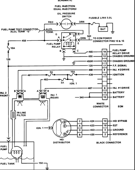
This is from the '86 manual:

http://tpiparts.net/85_89_maf_sensors/
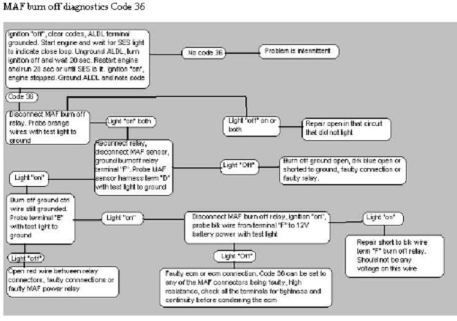
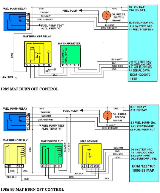
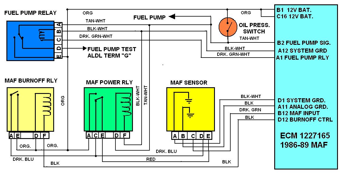
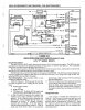
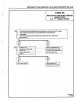
The MAF Power Relay is called the Mass Burn Off Control Relay in the schematic. The photos I have are too blurry to be of any use to you, but I can verify the schematic is correct. As raid's description does not match the schematic, I assume the 87 is different.
MORE USEFUL INFO
http://www.corvettefever.com/techarticl ... index.html
http://books.google.com/books?id=O2vA-v ... 1#PPA54,M1
http://www.corvettebuyers.com/c4vettes/maf.htm

QUOTE
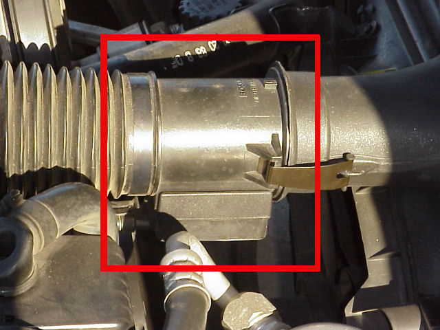
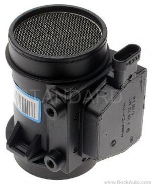
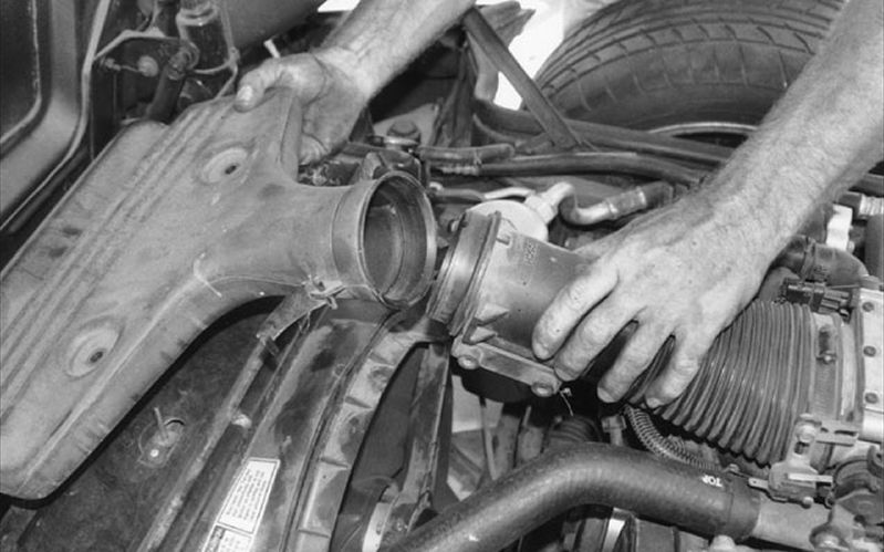
"Most of the C4 Corvettes used a MAF (Mass Air Flow) sensor to determine how much air is being pulled into the intake manifold. The exceptions are the 1984 Corvette that used a speed density system--a sort of predictive method of measurement---and the 1990 through 1993 C4 models which were also speed density based. In 1994, Corvette went back to the MAF based system but used the speed density approach as a back up. (1989 Bosch MAF installation shown at right).
A Mass Air Flow sensor has an extremely fine wire inside its bore. The 1985 through 1989 C4 engines used a Bosch MAF sensor that heated the wire to 100 C. The 1994 and later C4 models used a AC/Delco MAF that heated the wire to 200 C. The amount of current required to reach the temperature is measured in each case. (Note: the LT-5 engine used in the ZR-1 used a speed density system and continued to use that system in 1994 and 1995 since the engines had already been made prior to the last two years of production. The ZR-1 therefore has no MAF even after Corvette went back to the MAF based system).
Theory of Operation
As the air travels past the heated wire enroute to the intake manifold, it will cool the wire and additional current is added to again heat the wire to the design temperature. Since the amount of air moving past the sensor is directly related to the amount of cooling experienced by the heated wire, a feedback condition is established whereby the exact amount of moving air is directly related to the amount of current passing through the wire and the intake air is therefore precisely measured.
Once the amount of air is known, the computer controlling the engine can add or subtract fuel as required to maintain the magic 14.7:1 air-fuel mixture resulting in the cleanest burn possible from an emissions (pollution) standpoint.
It does this by varying the "on time" of the fuel injectors. The injectors are pulsed on and off and the width of the pulse is lengthened or shortened as required. When you first start a typical engine, the pulse width is around 4 milliseconds but as soon as the engine "catches" the pulse width is shortened to about 2.2 milliseconds for idle. During operation, the measured air flow through the MAF will cause the computer to increase or decrease the pulse width as explained above.
MAF Operating Conditions
The Bosch MAF is more complex than the AC/Delco version. Both measure the air flow but the Bosch MAF has a circuit called the 'burn-off circuit' that cycles on for about 2 seconds when you shut the engine down. This circuit heats the wire to a high enough temperature to burn off any residue that may have collected on the wire during operation. If you are in a quiet area, you can hear the relays click on and then off on a 1985-1989 C4 as the burn-off cycle occurs.
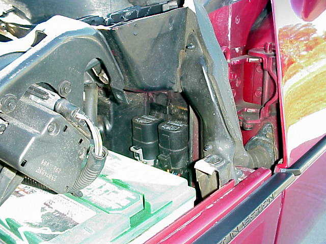
There are two relays involved with the Bosch MAF: A power relay that passes current to the MAF wire during normal operation and the burn-off relay that provides the current for the cleaning cycle. Both are located on the firewall in the engine compartment, just behind the battery on the drivers side. Bad MAF power and burn-off relays can cause hard starting problems and should be changed periodically as preventative measure and any time you experience hard starting conditions.
The AC/Delco MAF has a power relay but no burn-off relay. For this reason, you should pay even closer attention to the condition of your air filter on a later model C4 than normal since a contaminated wire in a AC/Delco MAF is going to stay contaminated for the most part and cause false signals to be passed to the computer.
Also, the Bosch MAF outputs its information as a analog signal to the computer but the AC/Delco sends its signal as a digital component of varying frequency. For this reason, you cannot measure it's operation directly.
A scan tool is generally the best way to troubleshoot engine problems and with the 1994 and later Corvette, it is virtually mandatory. (An oscilloscope will also work on the AC/Delco MAF but a regular test meter will not).
MAF Problems
Faulty MAF sensors will normally light the check engine light on the drivers information center if the problem is constant and store a trouble code. If intermittent, a trouble code will still be stored as long as the battery is not disconnected.
Normally, the problem is a poor connection at the sensor and wiggling the wires, unplugging and reinserting the connector will often cure the problem.
A faulty MAF will normally cause a no start or difficult start condition and although you can eventually get the car into the "limp-home" mode in most cases, you need to attend to the problem ASAP.
AC/Delco sensors can become intermittent or give false readings if the wires become contaminated as explained above.
The MAF is a critical part of the emission control system and as such will cause the computer to react to problems very quickly, setting trouble codes and reducing performance in ways that cannot be ignored for long.
MAF Mods
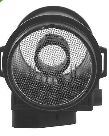
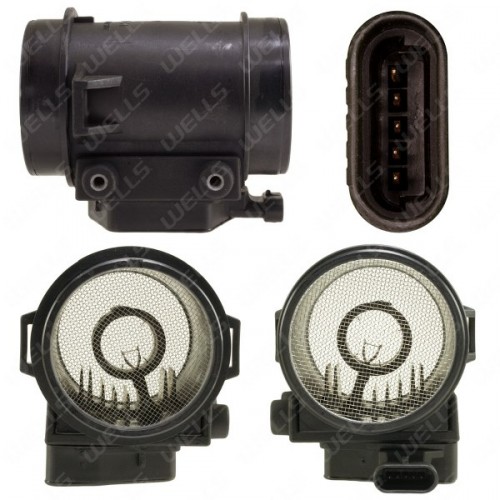
The Bosch MAF is often modified by removing the two screens that are present in the front and rear of the cylinder. Removing these screens significantly increases the air flow through them and this results in more horsepower. Removing the screens is an old trick from the Corvette Challenge days in 1988 and 1989. It does work but is illegal in many states so be advised not to do anything that will get you arrested for a pollution violation.
The AC/Delco MAF is not readily modified. It is what it is but since it is a larger diameter than the Bosch, it responds well to changing the air filter to a free flowing type such as the K&N filter."
http://tpiparts.net/85_89_maf_sensors/
The MAF Power Relay is called the Mass Burn Off Control Relay in the schematic. The photos I have are too blurry to be of any use to you, but I can verify the schematic is correct. As raid's description does not match the schematic, I assume the 87 is different.
MORE USEFUL INFO
http://www.corvettefever.com/techarticl ... index.html
http://books.google.com/books?id=O2vA-v ... 1#PPA54,M1
http://www.corvettebuyers.com/c4vettes/maf.htm
QUOTE
"Most of the C4 Corvettes used a MAF (Mass Air Flow) sensor to determine how much air is being pulled into the intake manifold. The exceptions are the 1984 Corvette that used a speed density system--a sort of predictive method of measurement---and the 1990 through 1993 C4 models which were also speed density based. In 1994, Corvette went back to the MAF based system but used the speed density approach as a back up. (1989 Bosch MAF installation shown at right).
A Mass Air Flow sensor has an extremely fine wire inside its bore. The 1985 through 1989 C4 engines used a Bosch MAF sensor that heated the wire to 100 C. The 1994 and later C4 models used a AC/Delco MAF that heated the wire to 200 C. The amount of current required to reach the temperature is measured in each case. (Note: the LT-5 engine used in the ZR-1 used a speed density system and continued to use that system in 1994 and 1995 since the engines had already been made prior to the last two years of production. The ZR-1 therefore has no MAF even after Corvette went back to the MAF based system).
Theory of Operation
As the air travels past the heated wire enroute to the intake manifold, it will cool the wire and additional current is added to again heat the wire to the design temperature. Since the amount of air moving past the sensor is directly related to the amount of cooling experienced by the heated wire, a feedback condition is established whereby the exact amount of moving air is directly related to the amount of current passing through the wire and the intake air is therefore precisely measured.
Once the amount of air is known, the computer controlling the engine can add or subtract fuel as required to maintain the magic 14.7:1 air-fuel mixture resulting in the cleanest burn possible from an emissions (pollution) standpoint.
It does this by varying the "on time" of the fuel injectors. The injectors are pulsed on and off and the width of the pulse is lengthened or shortened as required. When you first start a typical engine, the pulse width is around 4 milliseconds but as soon as the engine "catches" the pulse width is shortened to about 2.2 milliseconds for idle. During operation, the measured air flow through the MAF will cause the computer to increase or decrease the pulse width as explained above.
MAF Operating Conditions
The Bosch MAF is more complex than the AC/Delco version. Both measure the air flow but the Bosch MAF has a circuit called the 'burn-off circuit' that cycles on for about 2 seconds when you shut the engine down. This circuit heats the wire to a high enough temperature to burn off any residue that may have collected on the wire during operation. If you are in a quiet area, you can hear the relays click on and then off on a 1985-1989 C4 as the burn-off cycle occurs.
There are two relays involved with the Bosch MAF: A power relay that passes current to the MAF wire during normal operation and the burn-off relay that provides the current for the cleaning cycle. Both are located on the firewall in the engine compartment, just behind the battery on the drivers side. Bad MAF power and burn-off relays can cause hard starting problems and should be changed periodically as preventative measure and any time you experience hard starting conditions.
The AC/Delco MAF has a power relay but no burn-off relay. For this reason, you should pay even closer attention to the condition of your air filter on a later model C4 than normal since a contaminated wire in a AC/Delco MAF is going to stay contaminated for the most part and cause false signals to be passed to the computer.
Also, the Bosch MAF outputs its information as a analog signal to the computer but the AC/Delco sends its signal as a digital component of varying frequency. For this reason, you cannot measure it's operation directly.
A scan tool is generally the best way to troubleshoot engine problems and with the 1994 and later Corvette, it is virtually mandatory. (An oscilloscope will also work on the AC/Delco MAF but a regular test meter will not).
MAF Problems
Faulty MAF sensors will normally light the check engine light on the drivers information center if the problem is constant and store a trouble code. If intermittent, a trouble code will still be stored as long as the battery is not disconnected.
Normally, the problem is a poor connection at the sensor and wiggling the wires, unplugging and reinserting the connector will often cure the problem.
A faulty MAF will normally cause a no start or difficult start condition and although you can eventually get the car into the "limp-home" mode in most cases, you need to attend to the problem ASAP.
AC/Delco sensors can become intermittent or give false readings if the wires become contaminated as explained above.
The MAF is a critical part of the emission control system and as such will cause the computer to react to problems very quickly, setting trouble codes and reducing performance in ways that cannot be ignored for long.
MAF Mods
The Bosch MAF is often modified by removing the two screens that are present in the front and rear of the cylinder. Removing these screens significantly increases the air flow through them and this results in more horsepower. Removing the screens is an old trick from the Corvette Challenge days in 1988 and 1989. It does work but is illegal in many states so be advised not to do anything that will get you arrested for a pollution violation.
The AC/Delco MAF is not readily modified. It is what it is but since it is a larger diameter than the Bosch, it responds well to changing the air filter to a free flowing type such as the K&N filter."