Main Air Bleed Info

bytor

Well-Known Member
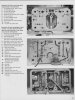
Sharing a graph the I ran across a few years ago depicting the AFR response to the main circuit jet, main air bleed, emulsion hole and kill bleed changes. The + and - represent an increase or decrease in orifices size. It helped me understand the nonliner affect the air bleeds and emulsion holes have on the AFR. This also represents how a larger air bleed = richer AFR when the main circuit starts up due to the emulsion effect.
 

Attachments

  • MainCircuitGraph.GIF
    MainCircuitGraph.GIF
    17.7 KB · Views: 89

Thanks for the info!

I had to google the term "Kill Bleed" and in the process came across this picture
identifying the passages in a carburetor. One person said that the top hole of #22
is the kill bleed, don't know if that is correct or not.

Another name for "Kill Bleed" is Anti-Siphon.


Attachments

  • CarbPassageID.jpg
    CarbPassageID.jpg
    85.7 KB · Views: 84
Indycars said:

Thanks for the info!

I had to google the term "Kill Bleed" and in the process came across this picture
identifying the passages in a carburetor. One person said that the top hole of #22
is the kill bleed, don't know if that is correct or not.

Another name for "Kill Bleed" is Anti-Siphon.

Yep, my understanding is the kill bleed primarily prevents the boosters from siphoning fuel when the butterflies slam shut. But, it also has some control on when the boosters start up.
 
Back
Top