Make Your Own Carburetor Jets & More

Indycars

Administrator
Staff member

I found this quite interesting to find out I could make my own jets. The cost would be considerably less than buying them and give another reason to buy some drill bits.

The quote below was posting by Madbill on speedtalk.


Having just gone through it, I will recount my procedure for fabricating jets and converting metering blocks. Hopefully the experts will chime in if I'm off base anywhere!

Build Your Own Jets
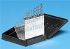
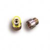
1. Get a box (50 for < six bucks!) of 8-32 x ⅛" brass socket head set screws from MacMaster-Carr or similar source http://www.mcmaster.com/#set-screws/=lpz9ow
p.n. 92991A188.

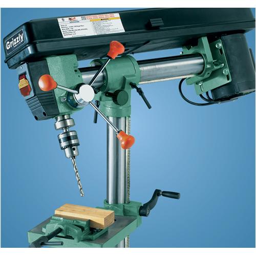
2. In a drill press, drill and tap a flat scrap of metal to 8-32, making the thread quite shallow so the set screws will bottom out rather than spinning right on through when you drill them.

3. Run a set screw down snug in the hole.

4. Find a pin vice with a straight shank that can be chucked in the drill press and use it at high RPM with a good drill/tap fluid to drill the set screw to the desired size*. (The recessed socket head serves to center the bit.) *verify diameter with a mic or dial caliper, they are often mislocated in the drill index and/or off-spec.

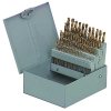
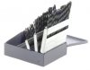
5. If you don't have and don't need a full set of number drills, most industrial fastener outlets will sell individual quality ones, although they may have a minimum charge, maybe $10, so this would be a good time to stock up on hacksaw blades or whatever. (My number drills are crap quality, so I use a good fraction bit first then 'ream' to size with the number drill.)

6. It shouldn't be a problem for gasoline applications, but the socket hex in an 8-32 screw is just under 0.090" across the points, so the maximum diameter must be enough less for the Allen key to get a grip.

7. I haven't yet done it, but my plan is to flow test my jets and discard any outliers. I have drilled and tapped a short length of steel tube and will screw the jets in (backwards, so the flow will be in the direction seen in service) and connect it to my 100 CC burette.

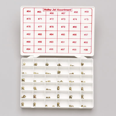
8. Plan 'B': Buy what sizes you need from Holley or one of the specialty carb shops for up to $5 each and then you don't have to worry about calibrating jet flows.

Savage Your Metering Block(s)
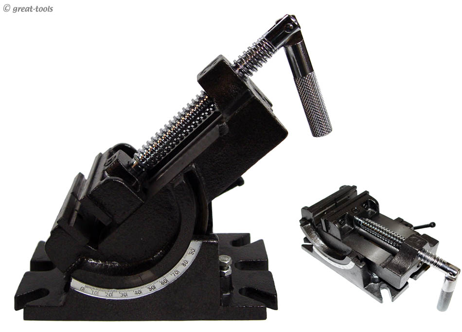
1. Clamp the block in a machinist's vice, with the snuggest possible fit number drill shank-down in one of the P.V.C.R. holes.

2. (I was a little A-R here, but better that than sloppy!) Use a digital angle finder to adjust the block position so that the drill bit is perfectly perpendicular to the drill press bed. (Alternative: Chuck the bit shank-out in the pin vice and adjust the block alignment until the drill drops smoothly into the P.V.C.R. without binding.

3. Mark the depth of the P.V.C.R. passage on the drill shank and transfer the measurement to the bit in step 4.

4. Drill with the correct tap drill for an 8-32 thread (#29 is specified, but a 9/64th is only a few thous larger and will work fine), being careful to not damage the block by going deeper than the above measurement.

5. Clamp an 8-32 tap in the drill chuck and, using tapping fluid, gently feed it into the hole while rotating the chuck by hand. If desired, once it is started the chuck can be loosened and the job completed with a tap handle. CAUTION: Start shallow and deepen if necessary; ideally the jet should seat on the thread runout with its head only a little below the surface of the PV recess.

6. Thoroughly blow out the well with compressed air, brake cleaner, etc. to be certain no shavings remain.

7 Repeat on remaining P.V.C.R.s

Calibrating Your Way to Double-Digit Fuel Economy in your 4.88:1, high stall 502

1. Ideally, the primary main jets should be reduced by road testing until lean surging or other unacceptable conditions develop at higher cruising speeds (low speed cruise is largely determined by idle and off-idle mixture), then stepped up a couple of sizes.

2. Next, the P.V.C.R. jets should be juggled to obtain desired WOT fueling, if necessary supplemented by small changes in the main jets.

3. CAUTION: With up to four variable jets each controlling primary and secondary AFR, It's really easy to lose track of fuel flow distribution! If at all possible, get the engine or at least the carb on an engine dyno and verify similar P & S fuel flow (for square carbs) or AFR (for carbs that are not symmetrical P to S)
 
Hey, Indy. I have done whats described in this post on my Speed Demon. It's relativity easy you just have to be very careful when drilling and taping the metering blocks. I used a pin vise and did it by hand very slowly. Then used a bottoming tap to tap the 8/32 hole. I did this for the idle feed restriction, emulsion holes, (shown in the picture below, you can see the 8/32 brass set screws in the IFR), power valve channel restriction, idle air bleed and high speed air bleed. The nice thing about doing this is you can easily manipulate all these orifices for ultimate tuning flexibility. On the flip side, you can cause yourself headaches by going to far out of spec and really screw up the carb calibration. But, you can always reset things back to factory baseline settings and start over again.
 

Attachments

  • IMG_0735-001.JPG
    IMG_0735-001.JPG
    309.7 KB · Views: 114

I guess it really would not be that hard to do, when I think about it. You took the idea and went even further with it for emulsion holes and the power valve channel restriction.

Were you able to start the bottoming tap without using any other tap first ???

 
your idea here has merit and Im sure youll find an adjustable vise and a drill press or mill comes in very handy
Like a welder a drill press with a decent vise to hold work is almost mandatory , in any guys work shop,and a MILL AND LATHE would obviously be ideal, but for most guys obviously find those tools too expensive and take up to much floor space, because I rarely see home shops with the larger tools


RELATED THREADS
viewtopic.php?f=27&t=970&p=2373&hilit=vise#p2373

viewtopic.php?f=27&t=4714&p=18266&hilit=+drill+bits#p18266

viewtopic.php?f=50&t=8340&p=29010&hilit=vise#p29010

3_angle_vise.jpg

g7946_det1.jpg


years ago I purchased two of these assortment packs when they cost about 1/2 the current price , Ive tried hard to keep 4 jets in each size in inventory as I use those, 72 jets in assorted sizes for $52 is still a good deal , and it gets better if you buy the pack or two of them, when summit posts a discount code
http://www.summitracing.com/parts/hly-36-181
hly-36-181.jpg


DrillSizeChart.gif

DrillCharts.gif
 
Carb Class: Best Jetting
http://www.quickfueltechnology.com/tech ... st-jetting
Question: I hear a lot of theories about best jetting. How do I know what the best jet is for my combination?
https://www.summitracing.com/parts/...MI3bORxpag6wIVlJgBCh3ISwMREAEYASABEgLILPD_BwE
Answer: The short and quick answer is whatever jetting produces the best MPH on your time slip. The long answer is a little more involved but the best MPH for given conditions (assuming a series of runs are being made the same day for testing purposes) is indicative of amount of fuel a given engine combination requires to produce the greatest horsepower (under the same weather conditions with no other changes). Disregarding the Elapsed Time for a moment, once the car gets settled down and accelerating to the finish line, variances in E.T. have very little effect on the MPH. Especially in the quarter mile, the mile per hour recorded has a direct correlation to the horsepower. Since we are jetting for best power, MPH is the point of reference we use. General recommendations are to go up or down, two jet sizes from your baseline runs. The baseline needs to consist of at least two runs. The safe approach initially

is to increase the jet size. After changing jet size, record how each change affects the MPH. An increase indicates the engine needs more fuel, a decrease means the engine needs less fuel. Continue to go up or down until the MPH drops below peak, then simply return to that jetting combination that produced the best MPH.

Question: When are the best weather conditions to do this kind of testing?

Answer: Weather conditions, more specifically Density Altitude can have a tremendous effect on both your engine’s performance as well as how much fuel it needs. Our recommendation is do your testing in the conditions you most frequently race under. If you live in a climate that is very hot during the summer and the on-set of night does not change the corrected altitude then the best jetting under those conditions should keep your engine happy in weather you most frequently race in. This step may require a separate Spring/Fall and Summer tune up. These separate tunings will help make it easier to predict your car’s consistency and repeatability. Pro competitors and Competition Eliminator tuners jet to the weather conditions because they are trying to extract every ounce of horsepower they can for the next round of competition. This isn’t necessary for bracket racing of course but when the jetting is very close to optimum the car’s performance even with nominal changes in weather, should be easier to predict.

Question: My buddy and I each bought EGT (Exhaust Gas Temperature) sensors for our engines this past year. I’m little confused we have similar engines but my engine runs better with a lower temperature than his. What’s the deal?

Answer: EGT’s are a great tuning tool and reading the temperatures after every run can be invaluable for diagnosing problems when the readings deviate a great deal from your norm. Unfortunately, your “norm” might be different than your buddy. There can be some real variances because the exhaust temperature is rising or building heat as you are making your run. Setting aside differences in the engines, like camshaft profile, timing, compression, etc. one engine can be running richer than the other at low RPMs and therefore starts out the run at a lower temperature. Naturally that richer idle and off idle system is going to build heat faster than the leaner engine. Additionally, when you get out of throttle at the end of the run, the richer idle system will keep the exhaust gas temperatures cooler. If there is only a small variance between the two engines at the finish line, don’t worry about it too much because that is where the greatest load occurs. Look at where in the RPM band the differences occur and that might be a tip off your engine is running richer (therefore the lower exhaust temperature) and perhaps concentrate your tuning efforts in at area.
 
Last edited by a moderator:
bytor said:
Hey, Indy. I have done whats described in this post on my Speed Demon. It's relativity easy you just have to be very careful when drilling and taping the metering blocks. I used a pin vise and did it by hand very slowly. Then used a bottoming tap to tap the 8/32 hole. I did this for the idle feed restriction, emulsion holes, (shown in the picture below, you can see the 8/32 brass set screws in the IFR), power valve channel restriction, idle air bleed and high speed air bleed. The nice thing about doing this is you can easily manipulate all these orifices for ultimate tuning flexibility. On the flip side, you can cause yourself headaches by going to far out of spec and really screw up the carb calibration. But, you can always reset things back to factory baseline settings and start over again.

Did you use an 8-32 set screw for all the orifices, or did some of them require a smaller 6-32 set screw ???

What size range of drills did you need for all the different jets?

 
Indycars said:
Did you use an 8-32 set screw for all the orifices, or did some of them require a smaller 6-32 set screw ???

What size range of drills did you need for all the different jets?


I'm almost positive I used 8/32 brass set screws for everything. They are good up to .070"ish orifice size. I'll verify the set screw size later today.

I just used you typical numbed drill sets.

One was 1-60.....


and the other was 61-80.....
 

Attachments

  • 26104_R.jpg
    26104_R.jpg
    12.2 KB · Views: 32
  • image_17460.jpg
    image_17460.jpg
    29 KB · Views: 81

I was hoping I wouldn't have to buy both sets of wire size drill bits, but if I want
to be able and measure all the orifices I will need both.

Looking at your what you posted, the only changes you made were in the 61-80
drill set and a 1/16".


Attachments

  • DemonDataByBytorPg13.jpg
    DemonDataByBytorPg13.jpg
    77.9 KB · Views: 27
Most of my time was spent with the #61-#80 sizes. But, you will need to have #50-#60 for your PVCR and air bleeds. Also needed to use as a gauge to verify your current setup.
 
Rick I know You like Fabricating from scratch parts.
Believe it or not Carburator jets are extremely precision made.
I have drilled them many times myself to get the larger size required.
Not everyhing on Speed Talk is exactly correct.
I get on there sometimes myself to read but don't post any there.
Big names like Joe Sherman and others sometimes present.

Carburator jets are typically reamed to size.
Reaming is much more accurate than drilling.
By using a tiny reamer tolerance can be held + ~ - .001".
A drilled hole can vary .005" or more.

Most precise way to drill machine metal is by EDM Machining.
Hold a tolerance down to a few Microns or Micro inch.

The cost if all has skyrocketed.
 
87vette81big said:
Rick I know You like Fabricating from scratch parts.
Believe it or not Carburator jets are extremely precision made.

I agree with not drilling the main fuel jets. The chamfer on the back side of the jet has a lot to do with the flow rating. When you drill them, you don't get a linear flow increase as you would expect. Stick with unaltered calibrated jets.


I believe Rick is referring to the various air jets like high/low speed air bleeds, PCVR, emulsion holes and such. I see no issues using drilled set screws for those applications.
 

Attachments

  • images.jpg
    images.jpg
    6.1 KB · Views: 11

I bought a selection of Main Jets when I bought the Demon carb, so I do have the
precision jets for the mains. I have also ordered everything I need to make all
the other jets/restrictor/air bleeds.

I have coming: 50 each of 6-32, 8-32, 10-32 brass set screws ; bottoming taps for
6-32, 8-32, 10-32 ; Drill Bit Sets 1 thru 80.

Brass Set Screws - http://www.mcmaster.com/#set-screws/=tdjgzb

http://www.amazon.com/gp/product/B0000T ... refresh_T1


http://www.amazon.com/gp/product/B002O0 ... refresh_T1


Attachments

  • DrillSet_Numbered_1-60.jpg
    DrillSet_Numbered_1-60.jpg
    12.8 KB · Views: 11
  • DrillSet_Numbered_61-80.jpg
    DrillSet_Numbered_61-80.jpg
    20.4 KB · Views: 11
Goes back almost 20 years now but someone was making Saphire & Ruby Orfice Main jets for Holley Carbs.
Drilled to size with a high powered Laser beam.
Best made & made very expensive.
Comp cams was selling them before they got real big & got Fffed up and selling crap junk like today.
Haven't seen them since those Ultra Holley Jets.
 
Hey, Indy. I have done whats described in this post on my Speed Demon. It's relativity easy you just have to be very careful when drilling and taping the metering blocks. I used a pin vise and did it by hand very slowly. Then used a bottoming tap to tap the 8/32 hole. I did this for the idle feed restriction, emulsion holes, (shown in the picture below, you can see the 8/32 brass set screws in the IFR), power valve channel restriction, idle air bleed and high speed air bleed. The nice thing about doing this is you can easily manipulate all these orifices for ultimate tuning flexibility. On the flip side, you can cause yourself headaches by going to far out of spec and really screw up the carb calibration. But, you can always reset things back to factory baseline settings and start over again.

Ok it is 5 years ago, so I hope you remember this. What size of jets you used in the emulsion holes? 8-32 too?
 
Thank you for the links, the first one helped. I ordered some set screws, but like every time when I order things from USA it takes time to get it here.
 
Did you check Amazon, they have them and should be in the EU I would think? Or an industrial supply.

What problem are you trying to solve with the emulsion tubes?
 
Back
Top