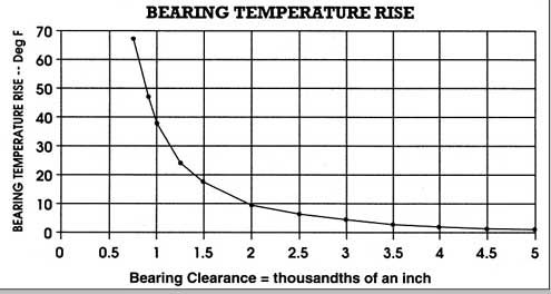
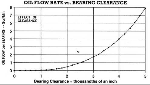
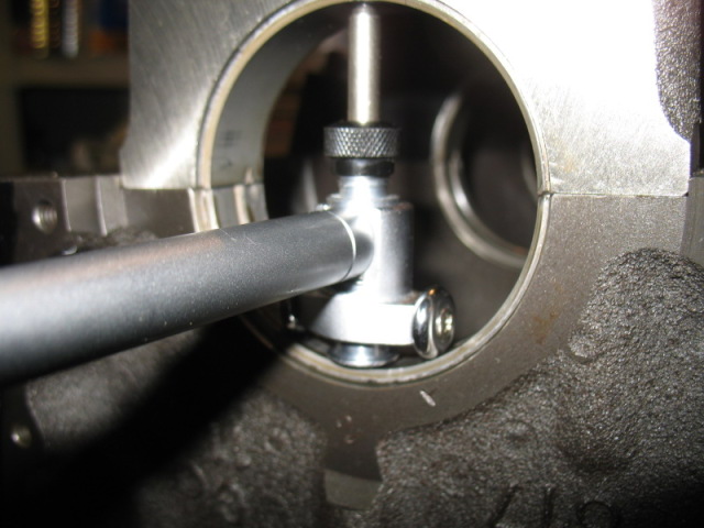
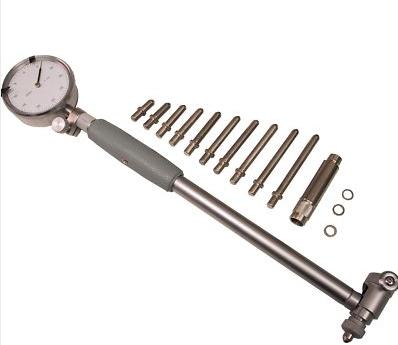
measuring your bearing clearances is critical, to both engine durability and controlling oil flow rates, am=nd maintaining full lubrication.
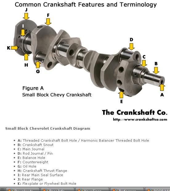
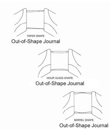
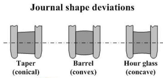
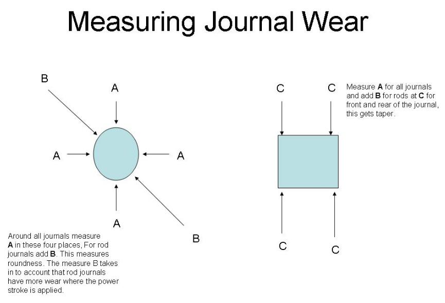
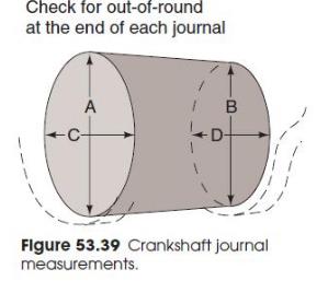
be sure to measure in several locations as a worn crank journal may have a taper or slight egg shape or cone shape to the journal, if you don,t measure at the 12, o'clock, 6 o'clock 3 o'clock 9 o'clock locations along the full length of the journal surface that may not be obvious if its only been checked in one location
theres also 180 degree or flat crank designs
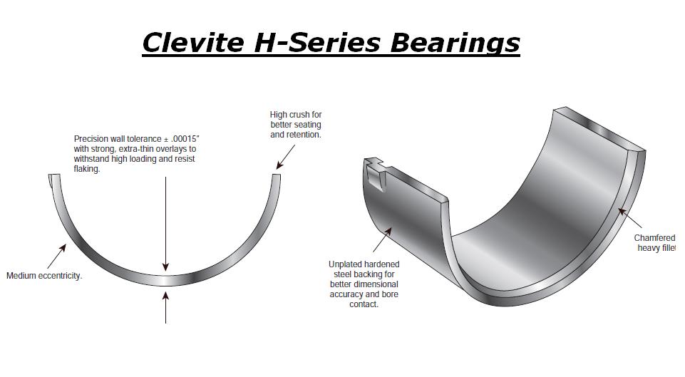
Ive generally found the H-series bearings are the best choice
Common assembly clearances
(ALWAYS consult your piston manufacturer for recommended clearances. Many pistons require a tighter bore)
Piston to bore 0.0055 - 0.0065" ( measured at centerline of wrist pin, perpendicular to pin)
Piston ring gap MINIMUM end clearances Top 0.022"
2nd 0.016"
Oil 0.016"
Wrist pin 0.0006 - 0.0008" in piston, 0.0008 - 0.0010" in rod for full floating pin (End play 0.0 - 0.005"
Rod bearings 0.002 - 0.025" , side clearance 0.010 - 0.020"
Main bearings 0.002 - 0.003" , 0.005 - 0.007 crankshaft end play
Piston to head clearance 0.035 MINIMUM including gasket (steel rods), 0.060" MINIMUM aluminum rods
Valve to piston clearance MINIMUM 0.020" exhaust , 0.010" intake NO VALVE FLOAT
Recommended: 0.080 intake, 0.100 Exhaust (steel rods) 0.100 intake, 0.120 Exhaust aluminum rods
MEASURE CAREFULLY
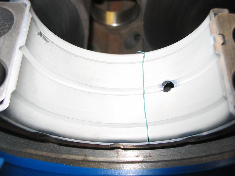
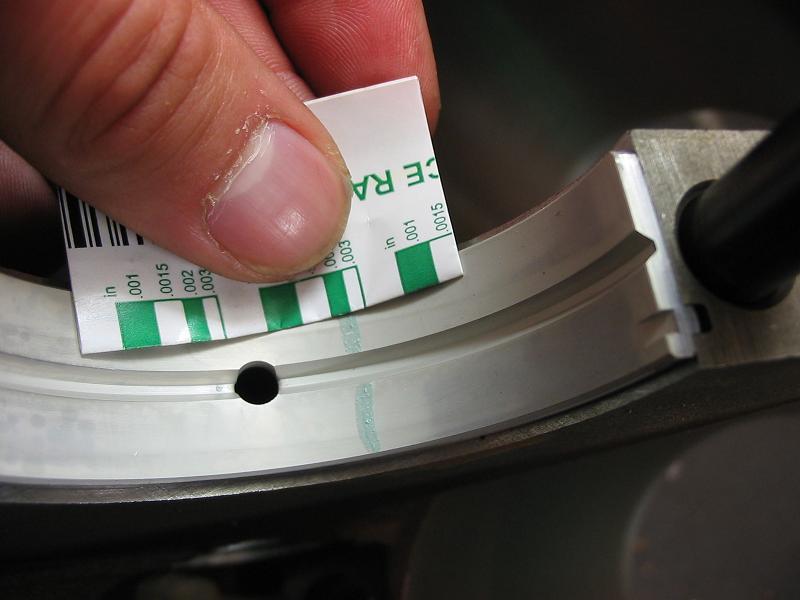
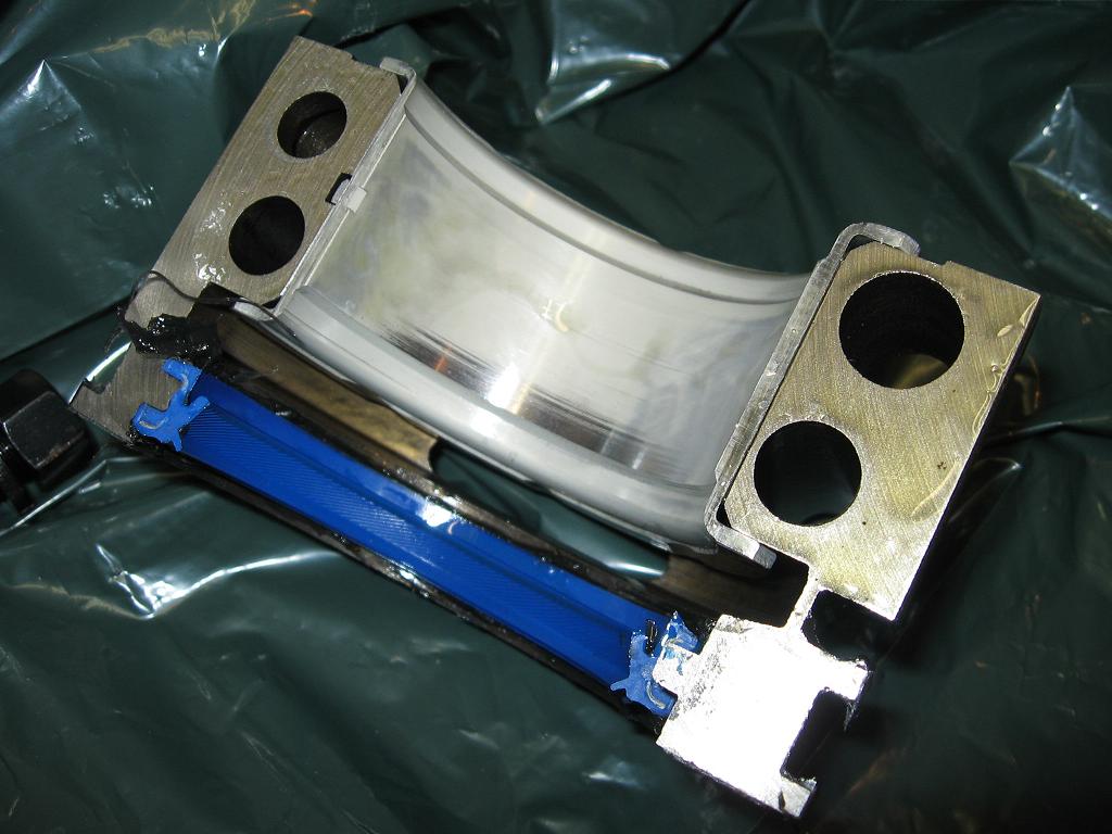
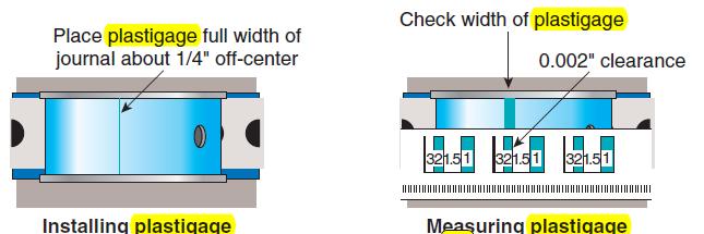
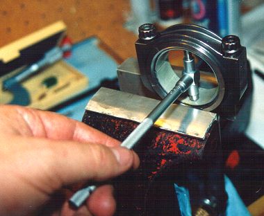
use plasti-gauge across the whole bearing as you can have a tapered journal thats correct in one area but loose or tight else-ware
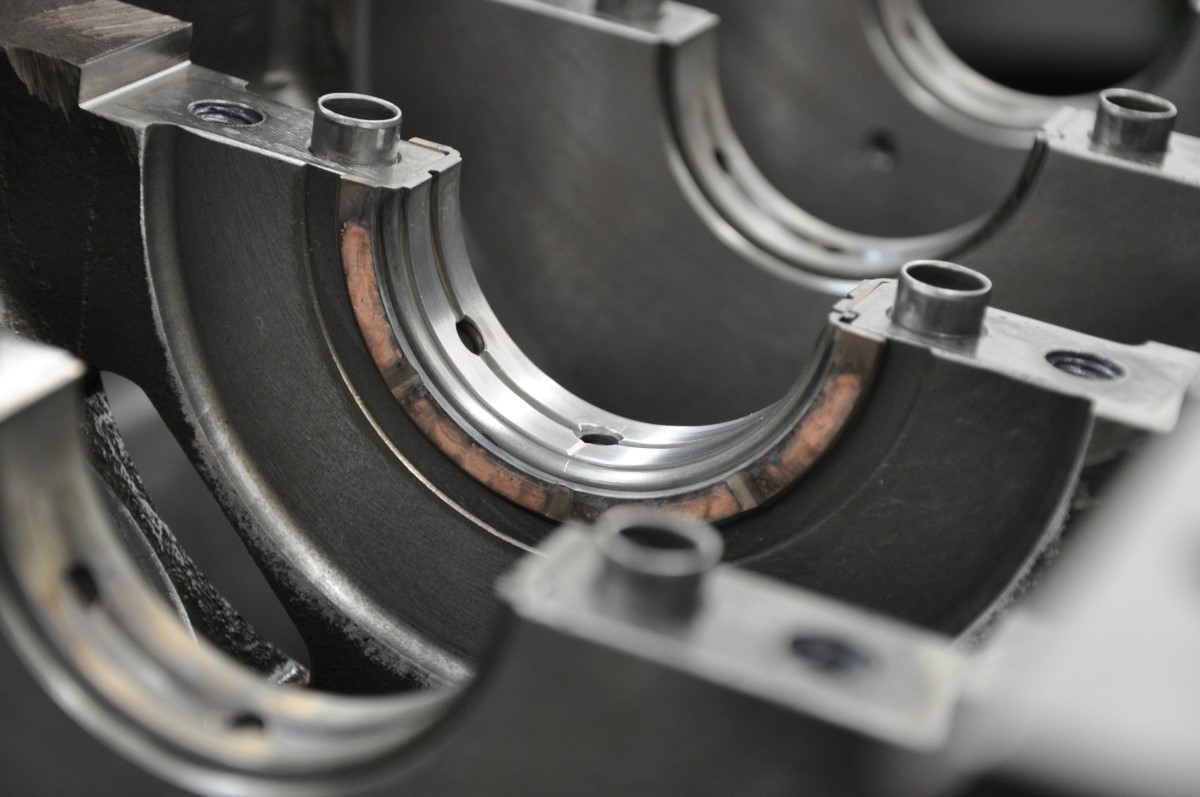
notice the bearing wears near the edge during the test fit indicating either the bearing is tapered or the bearing or main caps not seated correctly, in any case stop and find out whats causing the problem
IVE dunked my piston/ring assembly's in a can of MARVEL MYSTERY OIL just before installation with a ring compressor and have never seen the slightest indication of problems either on ring sealing getting the rings broken in, or on tearing the engines down later for inspections the amounts not that great, ideally each one installed adds a bit of resistance but at no time should the short block take over 40 ft lbs ABSOLUTE MAXIMUM to start it spinning,and LESS than 20 lbs to keep it moving, even with all the rings and pistons installed,yes you need to verify the bearing clearances during assembly and IT SHOULD take between 20lbs-25 lbs to start it spinning if the clearances are correct! and LESS than 20 lbs to keep it moving
IF it takes over 40 ft lbs to get it rotating ,youll need too DISASSEMBLE and FIND OUT WHY!
http://www.harborfreight.com/36-piece-3 ... 60669.html
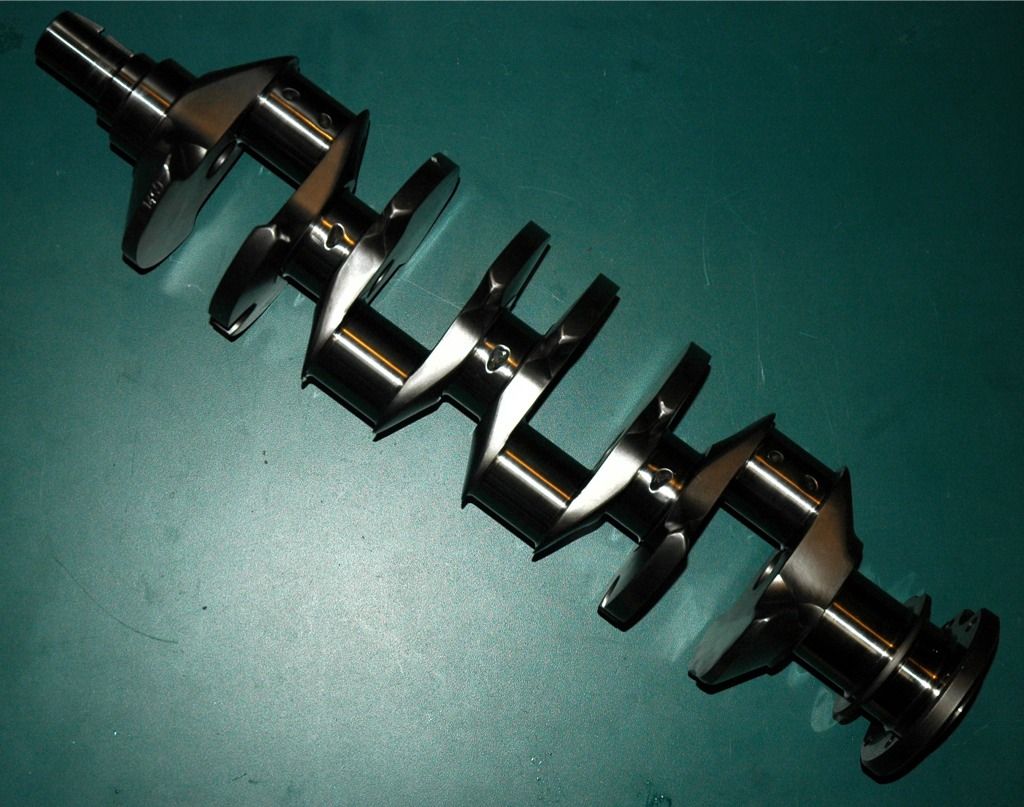
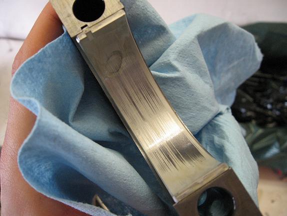
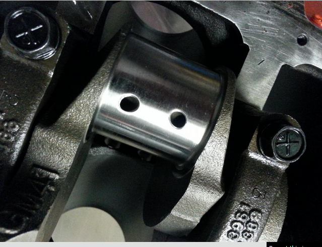
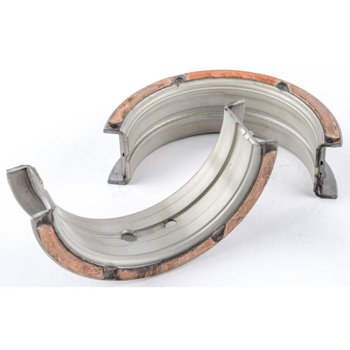
when you get the crank polished take the time and effort to clean out any cross drill oil feed passages and to very carefully de-burr the passage opening edges, as this is a very commonly overlooked issue, below is what at first looks like a perfectly polished crank, with oil feed passages to the rod bearings, but the deep scratches the oil feed passage openings left in the rod bearing surfaces bare witness, after a single rotation, during a trial assembly show they are HARDLY burr free or ready for use, and obviously he failed to check each rod bearing during the assembly process, and probably ignored , what was very likely un-even or rather excessive resistance to the crank rotation. which should never exceed about 40 ft lbs even with all 8 rod bearings and pistons installed
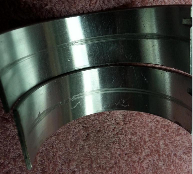
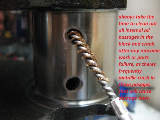
failure to clean out the oil passages in the block and crank journal cross feed oil holes, can and has frequently also resulted in trapped debris being flushed out and scoring the bearings during the test fit process in these bearings, an easily avoided but very common screw-up after a cam or bearing fails and your forced to do a ring, cam,lifter, and bearing replacement
http://www.stealth316.com/misc/clevite- ... ooving.pdf
http://stealth316.com/misc/clevite-77-r ... arings.pdf
http://kingbearings.com/files/Engine_Be ... erials.pdf
http://garage.grumpysperformance.co...ing-parts-and-a-logical-plan.7722/#post-72126
you might keep in mind bearing manufacturers are in business to sell bearings and if a small but consistent segment insists on buying and paying for 270 and 360 degree bearings the manufacturers will supply that demand to make a profit, they will also post tech bulletins explaining why a 180- degree oil feed groove in only the upper bearing shell provides a more durable bearing that carries more load capacity
http://garage.grumpysperformance.com/index.php?threads/can-i-get-it-polished.9214/
heres a quote from a bearing manufacturer
extending the main bearing groove much past 180 degrees increases friction, reduces load capacity costing hp, read the link
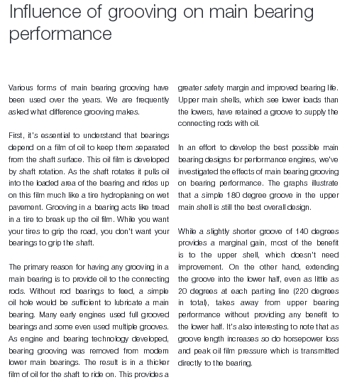
"Influence of Grooving on Main Bearing Performance
Various forms of main bearing grooving have been used over the years. We are
frequently asked what difference grooving makes.
First, it’s essential to understand that bearings depend on a film of oil to keep them
separated from the shaft surface. This oil film is developed by shaft rotation. As the shaft
rotates it pulls oil into the loaded area of the bearing and rides up on this film much like a
tire hydroplaning on wet pavement. Grooving in a bearing acts like tread in a tire to break
up the oil film. While you want your tires to grip the road, you don’t want your bearings
to grip the shaft.
The primary reason for having any grooving in a main bearing is to provide oil to the
connecting rods. Without rod bearings to feed, a simple oil hole would be sufficient to
lubricate a main bearing. Many early engines used full grooved bearings and some even
used multiple grooves. As engine and bearing technology developed, bearing grooving
was removed from modern lower main bearings. The result is in a thicker film of oil for
the shaft to ride on. This provides a greater safety margin and improved bearing life.
Upper main shells, which see lower loads than the lowers, have retained a groove to
supply the connecting rods with oil.
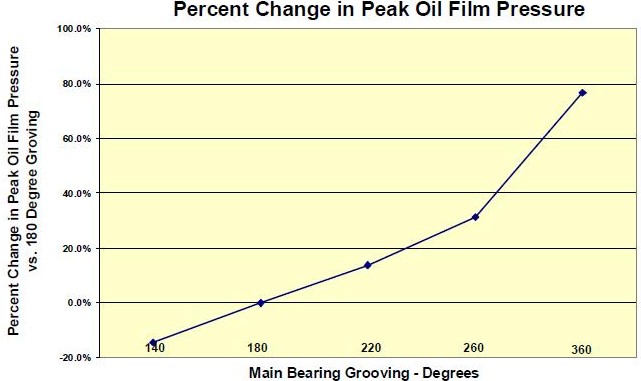
In an effort to develop the best possible main bearing designs for High Performance
engines, we’ve investigated the effects of main bearing grooving on bearing performance.
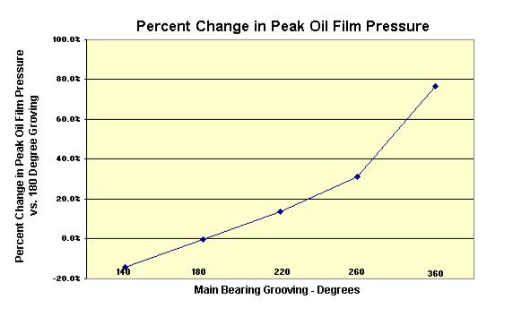
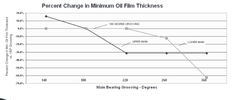
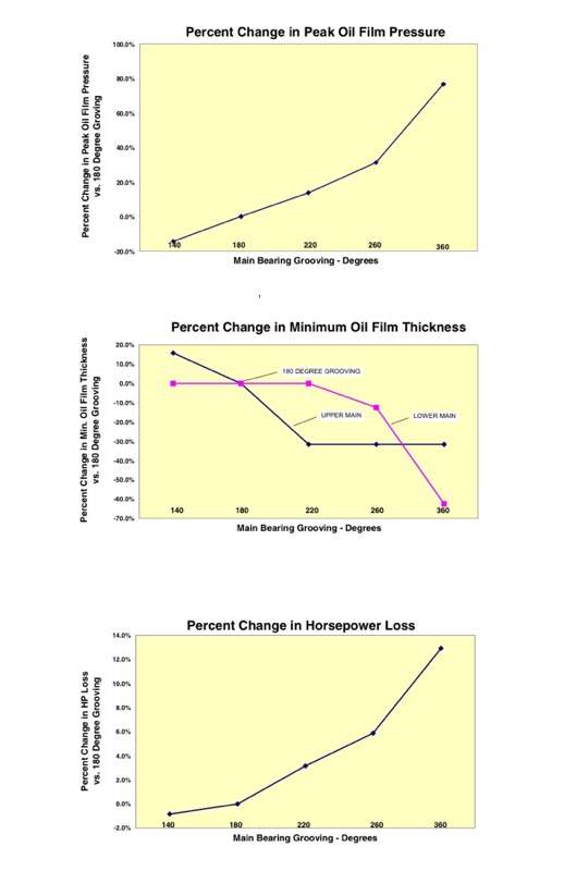
The graphs on the next page illustrate that a simple 180° groove in the upper main shell is
still the best overall design.
While a slightly shorter groove of 140° provides a marginal gain, most of the benefit is to
the upper shell, which doesn’t need improvement. On the other hand, extending the
groove into the lower half, even as little as 20° at each parting line (220° in total), takes
away from upper bearing performance without providing any benefit to the lower half.
It’s also interesting to note that as groove length increases so do Horsepower Loss and
Peak Oil Film Pressure which is transmitted directly to the bearing."
New
Hi Grumpy,
I caught your article on Journal measurements and would really appreciate your perspective on the followng questions. (background blather appears below the questions)
1) Shouldn't the journal in your article have looked shinier if it was a finish cut ? (see background below)
90% or more of the pictures were and are posted by other people on the internet , and merely used to illustrate, yes ideally a finish journal should be as close to mirror finished and glass smooth as you can get it, but level, from end to end except for the curved machined bevel,on each end ,its diameter concentric and even in its dimensions its intended and ideally standard size or standard under size, is critical
2) Is there a need to plasti-guage a daily driver crank (no racing) that's been resurfaced to a matching set of bearings ? I actually thought about plasti-gaging the journals rods from underneath (one location) but taking 6 measurements per makes removing the crank seem easier to do. I will definitely check for debris and burrs on future kits however.
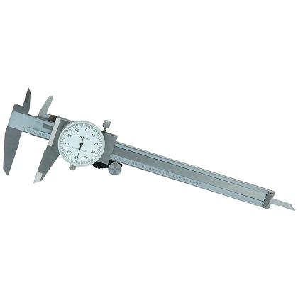
its always a good idea to verify machine work, theres always some machine shops that either do low quality or shoddy work, and you can,t expect an engine to operate correctly if the clearances or consistency of the bearing and lubrication surfaces are not correctly set, you would not bet the first or last guy to be told a crank was cut to a size that was not the true size or sold the wrong bearings for an application, you should always verify machine work, with both a precision measuring tool and plasti-gauge
MEASURE CAREFULLY
http://garage.grumpysperformance.com/index.php?threads/can-i-get-it-polished.9214/
http://garage.grumpysperformance.co...guess-on-clearances-and-journal-surface.9955/
http://garage.grumpysperformance.com/index.php?threads/bearing-clearances.2726/
http://garage.grumpysperformance.co...tion-of-crank-durring-short-blk-assembly.852/
http://garage.grumpysperformance.com/index.php?threads/rotating-assembly-bearings.9527/
3) Do you have any experience doing the crank kit right in the Caprice (without removing engine)
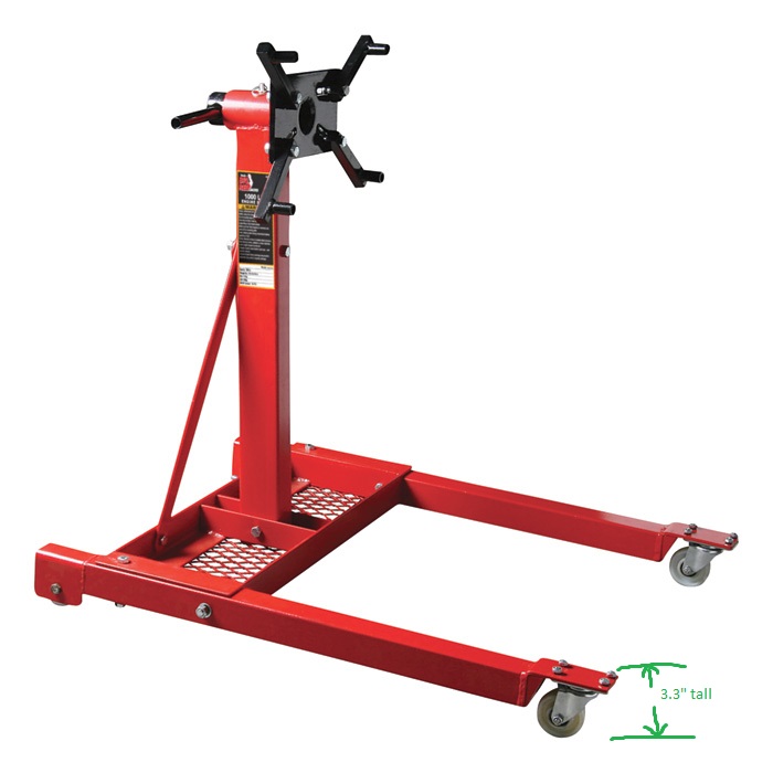
no I have always found it best too assemble an engine after placing it on a decent engine stand
if your going to assemble an engine you should buy or rent a decent engine stand, and a few basic tools
http://garage.grumpysperformance.co...g-with-a-local-machine-shop.14419/#post-74383
http://garage.grumpysperformance.co...haft-journal-surface-finnish.2728/#post-72043
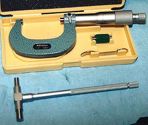
http://garage.grumpysperformance.com/index.php?threads/precision-measuring-tools.1390/#post-68850
4) I didn't understand from the graphs posted. What is a 180 'bearing' whatever vs a 270 ? and which is best and why ?
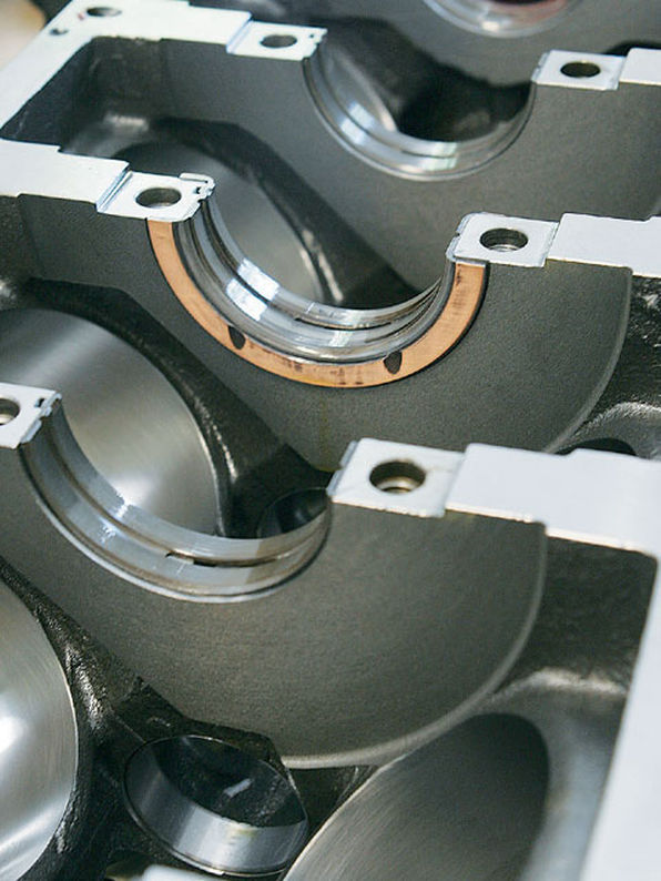
a 180 degree bearing has only the upper in the block grooved to improve oil flow,a 270 degree has the oil feed groove extend further 45 degrees on each lower bearing shell
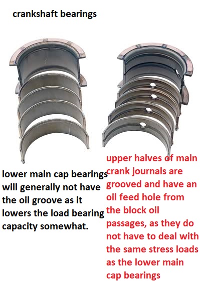
MAIN BEARINGS WITH 360 degree oil grooves
I've got my grandmothers 86 caprice that still looks really good and never fails to turn heads. Bone stock, but most of the cars been painted over 23 years I've owned it by a company that guarantees paint for life. More importantly this car has been just amazingly reliable over the years. Now that my son is ready to drive it (17) I'm noticing the engine shudders as second winds out so the bottoms loose with mileage just under 199K. I'm far from expert so did some googling and found your journal article.
I have done two crank shaft kits over the years - while the engines remained in the vehicles. 1975 and 1979 350 Chevy pickups. After reading the article I"ll have to say I don't recall checking nor deburing the oil passages - which would have been colossally easy to do. Will do so going forward. In both instances I pulled the crank had them resurfaced then bought bearings of matching thickness. The shop I turned the crank in 1990 has since closed so I'm checking out machine shops.
Note: The journal image in the article didn't look very shiny. Back during my 1990 crank kit install, I had the good fortune of comparing the journals of a crank that had been rough cut (per a racing engine builder) with my crank done by a shop owned by guys that raced engines. The difference was remarkable. I could easily see my pores, individual pores etc.. in the journals. They were mirrors. I installed it and drove my pickup daily to work 15 more years until gas hit $4/gallon then switched to the subject Caprice. Now my
RELATED THREADS YOU NEED TO READ, yeah it might take a couple hours but those would be WELL SPENT TIME
http://webtools.delmarlearning.com/samp ... _ch139.pdf
viewtopic.php?f=53&t=2726&p=7077&hilit=plastigauge#p7077
http://mechdb.com/index.php/Plastigagin ... clearances
http://www.circletrack.com/tipstricks/4 ... index.html
http://garage.grumpysperformance.com/index.php?threads/bearing-clearances.2726/#post-43385
http://www.jensenhealey.com/tech/plasti ... gauge.html
http://engineparts.com/techbulletins/CL77-1-205R.pdf
viewtopic.php?f=53&t=852
http://garage.grumpysperformance.co...guess-on-clearances-and-journal-surface.9955/
http://garage.grumpysperformance.com/index.php?threads/crankshaft-journal-surface-finnish.2728/
viewtopic.php?f=53&t=10213
viewtopic.php?f=54&t=150&p=184&hilit=+bearings+color#p184
viewtopic.php?f=53&t=88&p=112&hilit=+bearings+color#p112
viewtopic.php?f=50&t=1027&p=1902&hilit=bearings+undersize#p1902
viewtopic.php?f=53&t=2351&p=6453&hilit=bearings+undersize#p6453
viewtopic.php?f=53&t=2727
viewtopic.php?f=53&t=4419
viewtopic.php?f=53&t=4294
viewtopic.php?f=53&t=619
viewtopic.php?f=53&t=3449
viewtopic.php?f=50&t=989
viewtopic.php?f=50&t=342
viewtopic.php?f=50&t=1027
http://www.aa1car.com/library/ar797.htm
http://www.e30m3project.com/e30m3perfor ... /rods1.htm
http://www.circletrack.com/enginetech/c ... ce_basics/
http://mahleclevite.com/publications/EB-10-07.pdf
Engine Bearing Installation and Fitting Tips
When measuring bearing measurements, they should always be taken at 90-degrees to the parting line to determine the minimum clearance. If measuring the bearing wall thickness, use a special micrometer with a ball anvil to fit the curvature of the bearing ID. The best way to determine bearing clearance is to measure the bearing ID with the bearings installed in the housing and the bolts torqued to the specified assembly torque. Use a dial bore gauge to measure the bearing ID at 90-degrees to the parting line, then subtract shaft size from bearing ID to determine the clearance. If the dial bore gauge is zeroed at the actual diameter of the crankshaft journal to be installed, the dial bore gauge will then read clearance directly and the subtraction calculation can be eliminated. About .001" clearance per inch of shaft diameter is a good rule of thumb. Increasing that by about .0005" will add a little margin of safety when starting out, especially for rods. Example: .001" X 2.100 = .0021" then add .0005", so starting out set clearance at .0026" for a 2.100 shaft.
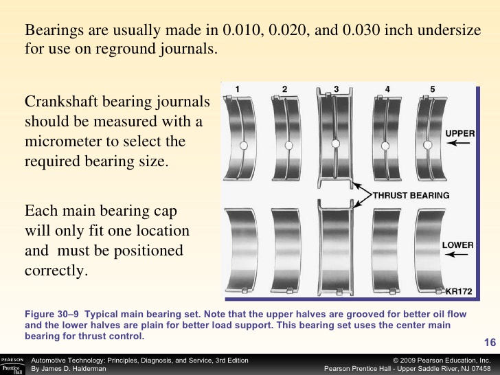
If clearance adjustments need to be made, use either an extra clearance part for more clearance or an undersize part for less clearance. It is permissible to mix sizes if less than .001" adjustment in clearance is desired. When mixing sizes for a select fitting: a) never mix parts having more than .0005" difference in wall size; b) and always install the thickest wall shell in the upper position if installing a rod bearing or the lower position if installing a main bearing. When working with a reground shaft, always measure assembled bearing ID's first. Next have a shaft sized to produce the desired clearance since there are no extra clearance parts available for undersize shafts.
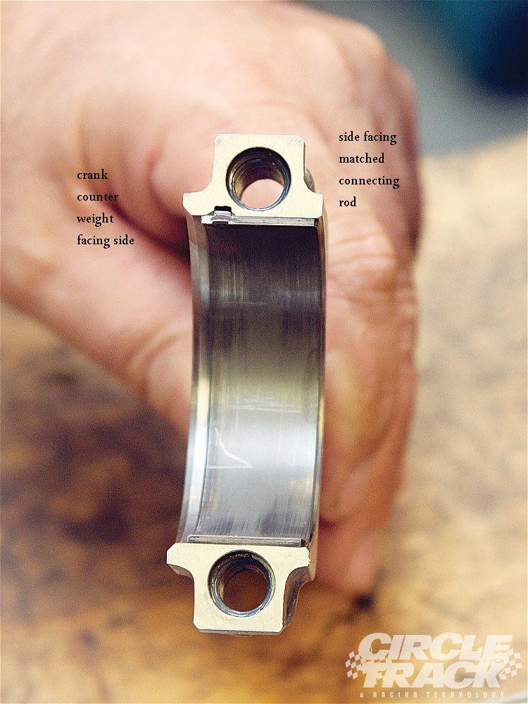
When measuring a bearing ID or wall thickness, avoid measuring at the parting line. The diagram illustrates there is a parting line relief machined into nearly all bearing shells. This relief is to allow for any mis-match between upper and lower shells due to tolerance differences, or possibly resulting from cap shift or twist during assembly. To determine bearing wall eccentricity or assembled bearing ID ovality, measure at a point at least 3/8" away from the parting line.
When installing any bearing DO NOT ATTEMPT TO POLISH THE BEARING RUNNING SURFACE WITH ANY TYPE OF ABRASIVE PAD OR PAPER. Bearing overlay layers are extremely soft and thin – typically .0005" on high performance parts. These thin layers can easily be damaged or removed by an abrasive media. Because the overlay layer is electroplated, it may exhibit microscopic plating nodules that make it feel slightly rough. The nodules are the same material as the rest of the plated layer and will quickly be flattened by the shaft. Bearing surfaces can be lightly burnished with solvent and a paper towel if desired.
Chevy V8 bore & stroke chart
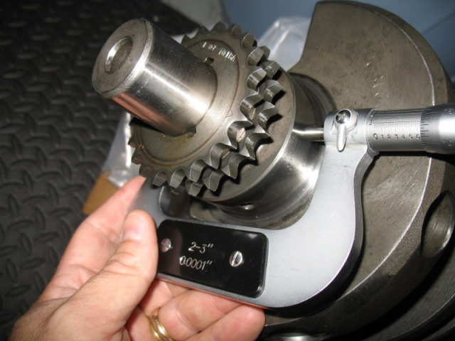
always accurately measure the crank main journals, and remember the crank and block bearing sizes on a 400 sbc and 350 smc are different as are the early 283-327 sbc
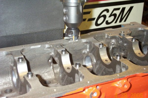
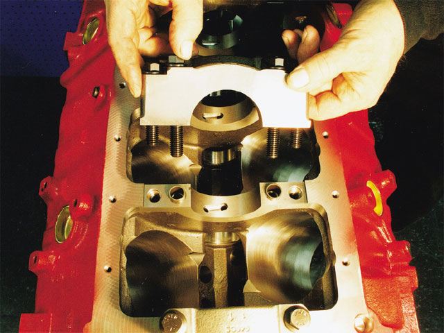
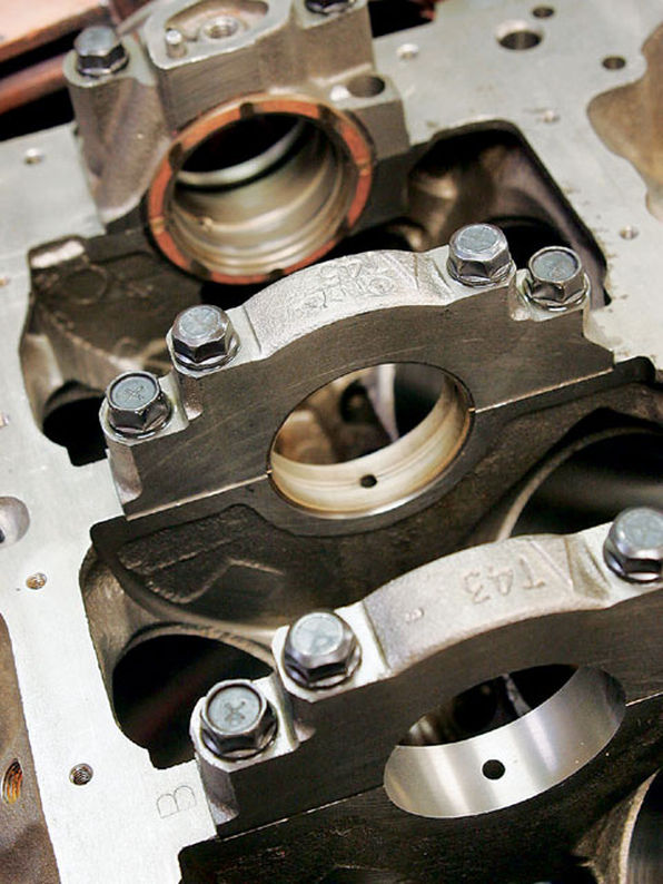
keep in mind both the main caps base and the area in the block must be machine precisely parallel , and there is a slight interference fit into a slight recess in the block on most engines to help prevent the caps moving once tightened into place by the main cap bolts or main cap studs. on some performance engines its fairly common for a hollow sleeve,s inserted 1/2 its short length, into the block and 1/2 its length into a shallow recess into the main caps, too fit into matching recesses around the main cap studs , this locates and prevents lateral movement of the main caps
CHEVY SMALLBLOCK V-8 BORE AND STROKE
262 = 3.671" x 3.10" (Gen. I, 5.7" rod)
265 = 3.750" x 3.00" ('55-'57 Gen.I, 5.7" rod)
265 = 3.750" x 3.00" ('94-'96 Gen.II, 4.3 liter V-8 "L99", 5.94" rod)
267 = 3.500" x 3.48" (Gen.I, 5.7" rod)
283 = 3.875" x 3.00" (Gen.I, 5.7" rod)
293 = 3.779" x 3.27" ('99-later, Gen.III, "LR4" 4.8 Liter Vortec, 6.278" rod)
302 = 4.000" x 3.00" (Gen.I, 5.7" rod)
305 = 3.736" x 3.48" (Gen.I, 5.7" rod)
307 = 3.875" x 3.25" (Gen.I, 5.7" rod)
325 = 3.779" x 3.622" ('99-later, Gen.III, "LM7", "LS4 front wheel drive V-8" 5.3 Liter Vortec, 6.098" rod)
327 = 4.000" x 3.25" (Gen.I, 5.7" rod)
345 = 3.893" x 3.622" ('97-later, Gen.III, "LS1", 6.098" rod)
350 = 4.000" x 3.48" (Gen.I, 5.7" rod)
350 = 4.000" x 3.48" ('96-'01, Gen. I, Vortec, 5.7" rod)
350 = 3.900" x 3.66" ('89-'95, "LT5", in "ZR1" Corvette 32-valve DOHC, 5.74" rod)
364 = 4.000" x 3.622" ('99-later, Gen.III, "LS2", "LQ4" 6.0 Liter Vortec, 6.098" rod)
376 = 4.065" x 3.622" (2007-later, Gen. IV, "L92", Cadillac Escalade, GMC Yukon)
383 = 4.000" x 3.80" ('00, "HT 383", Gen.I truck crate motor, 5.7" rod)
400 = 4.125" x 3.75" (Gen.I, 5.565" rod)
427 = 4.125" x 4.00" (2006 Gen.IV, LS7 SBC, titanium rods)
Two common, non-factory smallblock combinations:
377 = 4.155" x 3.48" (5.7" or 6.00" rod)
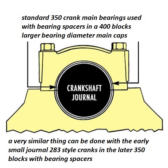
400 block and a 350 crank with "spacer" main bearings
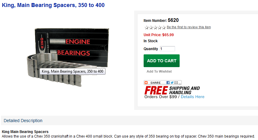
383 = 4.030" x 3.75" (5.565" or 5.7" or 6.0" rod)
350 block and a 400 crank, main bearing crank journals
cut to 350 size
CHEVY BIG BLOCK V-8 BORE AND STROKE
366T = 3.935" x 3.76"
396 = 4.096" x 3.76"
402 = 4.125" x 3.76"
427 = 4.250" x 3.76"
427T = 4.250" x 3.76"
454 = 4.250" x 4.00"
496 = 4.250" x 4.37" (2001 Vortec 8100, 8.1 liter)
502 = 4.466" x 4.00"
572T = 4.560" x 4.375" (2003 "ZZ572" crate motors)
T = Tall Deck
ALL production big blocks used a 6.135" length rod.
CHEVY 348-409 V-8 BORE AND STROKE
348 = 4.125" x 3.25" (6.125" rod)
409 = 4.312" x 3.50" (6.010" rod)
427 = 4.312" x 3.65" (6.135" rod) 1963 "Z11" SHP drag race
be sure to measure in several locations as a worn crank journal may have a taper or slight egg shape or cone shape to the journal, if you don,t measure at the 12, o'clock, 6 o'clock 3 o'clock 9 o'clock locations along the full length of the journal surface that may not be obvious if its only been checked in one location
theres also 180 degree or flat crank designs
Ive generally found the H-series bearings are the best choice
Common assembly clearances
(ALWAYS consult your piston manufacturer for recommended clearances. Many pistons require a tighter bore)
Piston to bore 0.0055 - 0.0065" ( measured at centerline of wrist pin, perpendicular to pin)
Piston ring gap MINIMUM end clearances Top 0.022"
2nd 0.016"
Oil 0.016"
Wrist pin 0.0006 - 0.0008" in piston, 0.0008 - 0.0010" in rod for full floating pin (End play 0.0 - 0.005"
Rod bearings 0.002 - 0.025" , side clearance 0.010 - 0.020"
Main bearings 0.002 - 0.003" , 0.005 - 0.007 crankshaft end play
Piston to head clearance 0.035 MINIMUM including gasket (steel rods), 0.060" MINIMUM aluminum rods
Valve to piston clearance MINIMUM 0.020" exhaust , 0.010" intake NO VALVE FLOAT
Recommended: 0.080 intake, 0.100 Exhaust (steel rods) 0.100 intake, 0.120 Exhaust aluminum rods
MEASURE CAREFULLY
use plasti-gauge across the whole bearing as you can have a tapered journal thats correct in one area but loose or tight else-ware
IVE dunked my piston/ring assembly's in a can of MARVEL MYSTERY OIL just before installation with a ring compressor and have never seen the slightest indication of problems either on ring sealing getting the rings broken in, or on tearing the engines down later for inspections the amounts not that great, ideally each one installed adds a bit of resistance but at no time should the short block take over 40 ft lbs ABSOLUTE MAXIMUM to start it spinning,and LESS than 20 lbs to keep it moving, even with all the rings and pistons installed,yes you need to verify the bearing clearances during assembly and IT SHOULD take between 20lbs-25 lbs to start it spinning if the clearances are correct! and LESS than 20 lbs to keep it moving
IF it takes over 40 ft lbs to get it rotating ,youll need too DISASSEMBLE and FIND OUT WHY!
http://www.harborfreight.com/36-piece-3 ... 60669.html
when you get the crank polished take the time and effort to clean out any cross drill oil feed passages and to very carefully de-burr the passage opening edges, as this is a very commonly overlooked issue, below is what at first looks like a perfectly polished crank, with oil feed passages to the rod bearings, but the deep scratches the oil feed passage openings left in the rod bearing surfaces bare witness, after a single rotation, during a trial assembly show they are HARDLY burr free or ready for use, and obviously he failed to check each rod bearing during the assembly process, and probably ignored , what was very likely un-even or rather excessive resistance to the crank rotation. which should never exceed about 40 ft lbs even with all 8 rod bearings and pistons installed
failure to clean out the oil passages in the block and crank journal cross feed oil holes, can and has frequently also resulted in trapped debris being flushed out and scoring the bearings during the test fit process in these bearings, an easily avoided but very common screw-up after a cam or bearing fails and your forced to do a ring, cam,lifter, and bearing replacement
http://www.stealth316.com/misc/clevite- ... ooving.pdf
http://stealth316.com/misc/clevite-77-r ... arings.pdf
http://kingbearings.com/files/Engine_Be ... erials.pdf
http://garage.grumpysperformance.co...ing-parts-and-a-logical-plan.7722/#post-72126
you might keep in mind bearing manufacturers are in business to sell bearings and if a small but consistent segment insists on buying and paying for 270 and 360 degree bearings the manufacturers will supply that demand to make a profit, they will also post tech bulletins explaining why a 180- degree oil feed groove in only the upper bearing shell provides a more durable bearing that carries more load capacity
http://garage.grumpysperformance.com/index.php?threads/can-i-get-it-polished.9214/
heres a quote from a bearing manufacturer
extending the main bearing groove much past 180 degrees increases friction, reduces load capacity costing hp, read the link
"Influence of Grooving on Main Bearing Performance
Various forms of main bearing grooving have been used over the years. We are
frequently asked what difference grooving makes.
First, it’s essential to understand that bearings depend on a film of oil to keep them
separated from the shaft surface. This oil film is developed by shaft rotation. As the shaft
rotates it pulls oil into the loaded area of the bearing and rides up on this film much like a
tire hydroplaning on wet pavement. Grooving in a bearing acts like tread in a tire to break
up the oil film. While you want your tires to grip the road, you don’t want your bearings
to grip the shaft.
The primary reason for having any grooving in a main bearing is to provide oil to the
connecting rods. Without rod bearings to feed, a simple oil hole would be sufficient to
lubricate a main bearing. Many early engines used full grooved bearings and some even
used multiple grooves. As engine and bearing technology developed, bearing grooving
was removed from modern lower main bearings. The result is in a thicker film of oil for
the shaft to ride on. This provides a greater safety margin and improved bearing life.
Upper main shells, which see lower loads than the lowers, have retained a groove to
supply the connecting rods with oil.
In an effort to develop the best possible main bearing designs for High Performance
engines, we’ve investigated the effects of main bearing grooving on bearing performance.
The graphs on the next page illustrate that a simple 180° groove in the upper main shell is
still the best overall design.
While a slightly shorter groove of 140° provides a marginal gain, most of the benefit is to
the upper shell, which doesn’t need improvement. On the other hand, extending the
groove into the lower half, even as little as 20° at each parting line (220° in total), takes
away from upper bearing performance without providing any benefit to the lower half.
It’s also interesting to note that as groove length increases so do Horsepower Loss and
Peak Oil Film Pressure which is transmitted directly to the bearing."
New
Hi Grumpy,
I caught your article on Journal measurements and would really appreciate your perspective on the followng questions. (background blather appears below the questions)
1) Shouldn't the journal in your article have looked shinier if it was a finish cut ? (see background below)
90% or more of the pictures were and are posted by other people on the internet , and merely used to illustrate, yes ideally a finish journal should be as close to mirror finished and glass smooth as you can get it, but level, from end to end except for the curved machined bevel,on each end ,its diameter concentric and even in its dimensions its intended and ideally standard size or standard under size, is critical
2) Is there a need to plasti-guage a daily driver crank (no racing) that's been resurfaced to a matching set of bearings ? I actually thought about plasti-gaging the journals rods from underneath (one location) but taking 6 measurements per makes removing the crank seem easier to do. I will definitely check for debris and burrs on future kits however.
its always a good idea to verify machine work, theres always some machine shops that either do low quality or shoddy work, and you can,t expect an engine to operate correctly if the clearances or consistency of the bearing and lubrication surfaces are not correctly set, you would not bet the first or last guy to be told a crank was cut to a size that was not the true size or sold the wrong bearings for an application, you should always verify machine work, with both a precision measuring tool and plasti-gauge
MEASURE CAREFULLY
http://garage.grumpysperformance.com/index.php?threads/can-i-get-it-polished.9214/
http://garage.grumpysperformance.co...guess-on-clearances-and-journal-surface.9955/
http://garage.grumpysperformance.com/index.php?threads/bearing-clearances.2726/
http://garage.grumpysperformance.co...tion-of-crank-durring-short-blk-assembly.852/
http://garage.grumpysperformance.com/index.php?threads/rotating-assembly-bearings.9527/
3) Do you have any experience doing the crank kit right in the Caprice (without removing engine)
no I have always found it best too assemble an engine after placing it on a decent engine stand
if your going to assemble an engine you should buy or rent a decent engine stand, and a few basic tools
http://garage.grumpysperformance.co...g-with-a-local-machine-shop.14419/#post-74383
http://garage.grumpysperformance.co...haft-journal-surface-finnish.2728/#post-72043
http://garage.grumpysperformance.com/index.php?threads/precision-measuring-tools.1390/#post-68850
4) I didn't understand from the graphs posted. What is a 180 'bearing' whatever vs a 270 ? and which is best and why ?
a 180 degree bearing has only the upper in the block grooved to improve oil flow,a 270 degree has the oil feed groove extend further 45 degrees on each lower bearing shell
MAIN BEARINGS WITH 360 degree oil grooves
I've got my grandmothers 86 caprice that still looks really good and never fails to turn heads. Bone stock, but most of the cars been painted over 23 years I've owned it by a company that guarantees paint for life. More importantly this car has been just amazingly reliable over the years. Now that my son is ready to drive it (17) I'm noticing the engine shudders as second winds out so the bottoms loose with mileage just under 199K. I'm far from expert so did some googling and found your journal article.
I have done two crank shaft kits over the years - while the engines remained in the vehicles. 1975 and 1979 350 Chevy pickups. After reading the article I"ll have to say I don't recall checking nor deburing the oil passages - which would have been colossally easy to do. Will do so going forward. In both instances I pulled the crank had them resurfaced then bought bearings of matching thickness. The shop I turned the crank in 1990 has since closed so I'm checking out machine shops.
Note: The journal image in the article didn't look very shiny. Back during my 1990 crank kit install, I had the good fortune of comparing the journals of a crank that had been rough cut (per a racing engine builder) with my crank done by a shop owned by guys that raced engines. The difference was remarkable. I could easily see my pores, individual pores etc.. in the journals. They were mirrors. I installed it and drove my pickup daily to work 15 more years until gas hit $4/gallon then switched to the subject Caprice. Now my
RELATED THREADS YOU NEED TO READ, yeah it might take a couple hours but those would be WELL SPENT TIME
http://webtools.delmarlearning.com/samp ... _ch139.pdf
viewtopic.php?f=53&t=2726&p=7077&hilit=plastigauge#p7077
http://mechdb.com/index.php/Plastigagin ... clearances
http://www.circletrack.com/tipstricks/4 ... index.html
http://garage.grumpysperformance.com/index.php?threads/bearing-clearances.2726/#post-43385
http://www.jensenhealey.com/tech/plasti ... gauge.html
http://engineparts.com/techbulletins/CL77-1-205R.pdf
viewtopic.php?f=53&t=852
http://garage.grumpysperformance.co...guess-on-clearances-and-journal-surface.9955/
http://garage.grumpysperformance.com/index.php?threads/crankshaft-journal-surface-finnish.2728/
viewtopic.php?f=53&t=10213
viewtopic.php?f=54&t=150&p=184&hilit=+bearings+color#p184
viewtopic.php?f=53&t=88&p=112&hilit=+bearings+color#p112
viewtopic.php?f=50&t=1027&p=1902&hilit=bearings+undersize#p1902
viewtopic.php?f=53&t=2351&p=6453&hilit=bearings+undersize#p6453
viewtopic.php?f=53&t=2727
viewtopic.php?f=53&t=4419
viewtopic.php?f=53&t=4294
viewtopic.php?f=53&t=619
viewtopic.php?f=53&t=3449
viewtopic.php?f=50&t=989
viewtopic.php?f=50&t=342
viewtopic.php?f=50&t=1027
http://www.aa1car.com/library/ar797.htm
http://www.e30m3project.com/e30m3perfor ... /rods1.htm
http://www.circletrack.com/enginetech/c ... ce_basics/
http://mahleclevite.com/publications/EB-10-07.pdf
Engine Bearing Installation and Fitting Tips
When measuring bearing measurements, they should always be taken at 90-degrees to the parting line to determine the minimum clearance. If measuring the bearing wall thickness, use a special micrometer with a ball anvil to fit the curvature of the bearing ID. The best way to determine bearing clearance is to measure the bearing ID with the bearings installed in the housing and the bolts torqued to the specified assembly torque. Use a dial bore gauge to measure the bearing ID at 90-degrees to the parting line, then subtract shaft size from bearing ID to determine the clearance. If the dial bore gauge is zeroed at the actual diameter of the crankshaft journal to be installed, the dial bore gauge will then read clearance directly and the subtraction calculation can be eliminated. About .001" clearance per inch of shaft diameter is a good rule of thumb. Increasing that by about .0005" will add a little margin of safety when starting out, especially for rods. Example: .001" X 2.100 = .0021" then add .0005", so starting out set clearance at .0026" for a 2.100 shaft.
If clearance adjustments need to be made, use either an extra clearance part for more clearance or an undersize part for less clearance. It is permissible to mix sizes if less than .001" adjustment in clearance is desired. When mixing sizes for a select fitting: a) never mix parts having more than .0005" difference in wall size; b) and always install the thickest wall shell in the upper position if installing a rod bearing or the lower position if installing a main bearing. When working with a reground shaft, always measure assembled bearing ID's first. Next have a shaft sized to produce the desired clearance since there are no extra clearance parts available for undersize shafts.
When measuring a bearing ID or wall thickness, avoid measuring at the parting line. The diagram illustrates there is a parting line relief machined into nearly all bearing shells. This relief is to allow for any mis-match between upper and lower shells due to tolerance differences, or possibly resulting from cap shift or twist during assembly. To determine bearing wall eccentricity or assembled bearing ID ovality, measure at a point at least 3/8" away from the parting line.
When installing any bearing DO NOT ATTEMPT TO POLISH THE BEARING RUNNING SURFACE WITH ANY TYPE OF ABRASIVE PAD OR PAPER. Bearing overlay layers are extremely soft and thin – typically .0005" on high performance parts. These thin layers can easily be damaged or removed by an abrasive media. Because the overlay layer is electroplated, it may exhibit microscopic plating nodules that make it feel slightly rough. The nodules are the same material as the rest of the plated layer and will quickly be flattened by the shaft. Bearing surfaces can be lightly burnished with solvent and a paper towel if desired.
Chevy V8 bore & stroke chart
always accurately measure the crank main journals, and remember the crank and block bearing sizes on a 400 sbc and 350 smc are different as are the early 283-327 sbc
keep in mind both the main caps base and the area in the block must be machine precisely parallel , and there is a slight interference fit into a slight recess in the block on most engines to help prevent the caps moving once tightened into place by the main cap bolts or main cap studs. on some performance engines its fairly common for a hollow sleeve,s inserted 1/2 its short length, into the block and 1/2 its length into a shallow recess into the main caps, too fit into matching recesses around the main cap studs , this locates and prevents lateral movement of the main caps
CHEVY SMALLBLOCK V-8 BORE AND STROKE
262 = 3.671" x 3.10" (Gen. I, 5.7" rod)
265 = 3.750" x 3.00" ('55-'57 Gen.I, 5.7" rod)
265 = 3.750" x 3.00" ('94-'96 Gen.II, 4.3 liter V-8 "L99", 5.94" rod)
267 = 3.500" x 3.48" (Gen.I, 5.7" rod)
283 = 3.875" x 3.00" (Gen.I, 5.7" rod)
293 = 3.779" x 3.27" ('99-later, Gen.III, "LR4" 4.8 Liter Vortec, 6.278" rod)
302 = 4.000" x 3.00" (Gen.I, 5.7" rod)
305 = 3.736" x 3.48" (Gen.I, 5.7" rod)
307 = 3.875" x 3.25" (Gen.I, 5.7" rod)
325 = 3.779" x 3.622" ('99-later, Gen.III, "LM7", "LS4 front wheel drive V-8" 5.3 Liter Vortec, 6.098" rod)
327 = 4.000" x 3.25" (Gen.I, 5.7" rod)
345 = 3.893" x 3.622" ('97-later, Gen.III, "LS1", 6.098" rod)
350 = 4.000" x 3.48" (Gen.I, 5.7" rod)
350 = 4.000" x 3.48" ('96-'01, Gen. I, Vortec, 5.7" rod)
350 = 3.900" x 3.66" ('89-'95, "LT5", in "ZR1" Corvette 32-valve DOHC, 5.74" rod)
364 = 4.000" x 3.622" ('99-later, Gen.III, "LS2", "LQ4" 6.0 Liter Vortec, 6.098" rod)
376 = 4.065" x 3.622" (2007-later, Gen. IV, "L92", Cadillac Escalade, GMC Yukon)
383 = 4.000" x 3.80" ('00, "HT 383", Gen.I truck crate motor, 5.7" rod)
400 = 4.125" x 3.75" (Gen.I, 5.565" rod)
427 = 4.125" x 4.00" (2006 Gen.IV, LS7 SBC, titanium rods)
Two common, non-factory smallblock combinations:
377 = 4.155" x 3.48" (5.7" or 6.00" rod)
400 block and a 350 crank with "spacer" main bearings
383 = 4.030" x 3.75" (5.565" or 5.7" or 6.0" rod)
350 block and a 400 crank, main bearing crank journals
cut to 350 size
CHEVY BIG BLOCK V-8 BORE AND STROKE
366T = 3.935" x 3.76"
396 = 4.096" x 3.76"
402 = 4.125" x 3.76"
427 = 4.250" x 3.76"
427T = 4.250" x 3.76"
454 = 4.250" x 4.00"
496 = 4.250" x 4.37" (2001 Vortec 8100, 8.1 liter)
502 = 4.466" x 4.00"
572T = 4.560" x 4.375" (2003 "ZZ572" crate motors)
T = Tall Deck
ALL production big blocks used a 6.135" length rod.
CHEVY 348-409 V-8 BORE AND STROKE
348 = 4.125" x 3.25" (6.125" rod)
409 = 4.312" x 3.50" (6.010" rod)
427 = 4.312" x 3.65" (6.135" rod) 1963 "Z11" SHP drag race
Last edited by a moderator: