one BIG ADVANTAGE to use of floating pin pistons and connecting rods it the ease of mixing and matching components and locations to minimize quench, or deck height differences during the install process
http://garage.grumpysperformance.co...in-height-compression-height.5064/#post-69254
SBC Head Gasket choice.
In a previous life the block was 0 decked then stroked to 383 and now the pistons sit out of the hole .015in, bore is 4.040in. Looking at readily available stock. Block wasn't particularly finished for MLS, heads Alum afr. Cometic isn't a choice. Daily driver. GMPP is the tightest at 4.100in...
garage.grumpysperformance.com
common BB CHEVY piston compression heights are
1.270"
1.395"
1.520"
1.645"
1.765"
remember the blocks deck height, minus the piston pin height minus 1/2 the crank stroke will equal the required connecting rod length
OR
the blocks deck height, minus the connecting rod length, minus 1/2 the crank stroke. will equal the required piston pin height
if you wonder why I suggest using SCAT (H) beam style cap screw connecting rods vs stock or most (I) beam designs this picture should show the increased cam to connecting rod clearance
After market performance ,big block connecting rods come in several common lengths
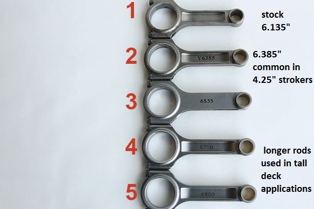
6.7-6.8"
https://www.summitracing.com/parts/esp-67003dl19/overview/make/chevrolet
https://www.summitracing.com/parts/cpi-u16230/overview/make/chevrolet
https://www.summitracing.com/parts/sca-6670022a/overview/make/chevrolet
https://www.summitracing.com/parts/sca-6680022a/overview/make/chevrolet
https://www.summitracing.com/parts/sca-6680022/overview/make/chevrolet
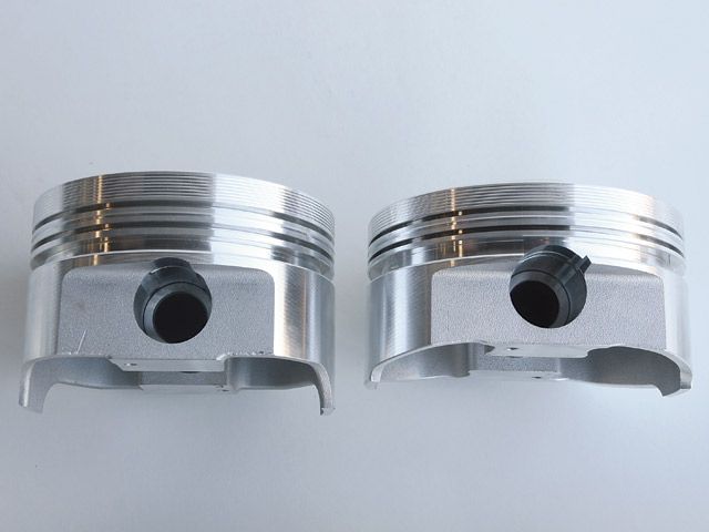
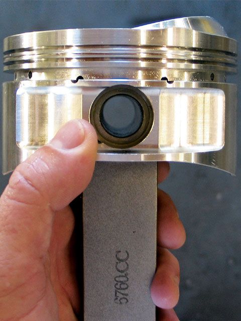
notice the pin height in the pistons pictured above allow a longer or shorter connecting rod length
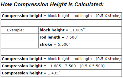
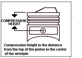
By definition, compression height is the distance from the center of the wristpin to the top of the piston, not including domes. This distance needs to change depending on the engine's stroke, rod length, and block deck height. Here's the formula to find out what compression height you need.
(1/2 stroke + rod length + desired piston-deck clearance) - block deck height = required piston compression height.
Here's an example for a small Chevy with a 3.5-inch stroke, 5.850-inch rods,
a desired deck clearance of 0.005 inch, and a deck height of 9.00.
(1.75 + 5.850 + 0.005) - 9.00 = 1.395
For example, a 350 Chevy engine with a stock 3.480 stroke, stock length 5.700 rod, standard .017 deck clearance and standard 9.025 block height would be:
3.480 stroke divided by 2 = 1.740
9.025 - 1.740 - 5.700 - .017 = a compression height of 1.568.
COMPRESSION RATIO -vs- COMPRESSION PRESSURE
Compression Ratio as a term sounds very descriptive. Compression ratio by itself, however, is like torque without RPM or tire diameter without a gear ratio. Compression ratio is only useful when other factors accompany it. Compression pressure is what the engine actually sees. High compression pressure increases the tendency toward detonation, while low compression pressure reduces performance and economy. Compression pressure varies in an engine every time the throttle is moved. Valve size, engine RPM, cylinder head, manifold and cam design, carburetor size, altitude, fuel engine/air temperature and compression ratio all combine to determine compression pressure. Supercharging and turbocharging can drastically alter compression pressures.
The goal of most performance engine designs is to utilize the highest possible compression pressure without causing detonation or a detonation-related failure. A full understanding of the interrelationship between compression ratio, compression pressure, and detonation is essential if engine performance is to be optimized. Understanding compression pressure is especially important to the engine builder that builds to a rule book that specifies a fixed compression ratio. The rule book engine may be restricted to a 9:1 ratio, but is usually not restricted to a specific compression pressure. Optimized air flow and cam timing can make a 9:1 engine act like a 10:1 engine. Restrictor plate or limited size carburetor engines can often run compression ratios impractical for unlimited engines. A 15:1 engine breathing through a restrictor plate may see less compression pressure than an 11:l unrestricted engine. The restrictor plate reduces the air to the cylinder and limits the compression pressure and lowers the octane requirements of the engine at higher RPM.
At one time compression pressure above a true 8:1 was considered impractical. It still is in many cases with today's gas. The heat of compression, plus residual cylinder head and piston heat, initiated detonation when 8:1 was exceeded. Some of the 60's 11:1 factory compression ratio engines were 11:1 in ratio, but only 8:1 in compression pressure. The pressure was reduced by closing the intake valve late. The late closing, long duration intake caused the engine to back pump the air/fuel mix into the intake manifold at speeds below 4500 RPM. The long intake duration prevented excess compresson pressure up to 4500 RPM and improved high RPM operation. Above 4500 RPM detonation was not a serious problem because the air/fuel mix entering the cylinder was in a high state of activity and the higher RPM limited cylinder pressure due to the short time available for cylinder filling.
The following compression guide should be considered realistic for sea level operation. Cam timing and special applications can move the recommendations around some, but in most cases the following recommendations work.
PUMP GAS (regular)
8.5:1-Non-quench 2 valve head road use standard sedan, without knock sensor.
8.5:1- Quench head engine for tow service, motor home and truck with torque cam.
9.0:1- Street engine with proper .040" quench, 200° @ .050" lift cam, iron head, sea level operation.
9.5:1- Same as 9:1 except aluminum head used. Light vehicle and no towing.
10:1- Used and built as the 9.5:1 engine with more than 220° @ .050" lift cam.
10:1- 4" and smaller bore, high RPM cam, cold plugs, good fuel distribution, full power limited to 30 seconds W.O.T.
RACE GAS
13:1- is the highest compression ratio suggested with unrestricted gasoline engines.
13:1- Plus o'kay with restricted intake engines at high RPM.
ALCOHOL
15.5:1- is the highest compression ratio suggested for unrestricted alcohol fuel engines. Probably will lose power at 15.5:1 in most applications.
Satisfactory use of 14:l - 17:1 compression engines can be made when restrictor plate or small carburetor use are mandated by race sanctioning. High altitude reduces cylinder pressure, so if you only drive at high (above 4500') altitude, a 10:1 engine can often be substituted for a 9:1 compression engine. General compression rules can be violated, but it is usually a very special case, such as a 600 Hp normally aspirated engine in a 1500 lb. street car with a 12:1 compression ratio. The radical cam timing necessary for this level of performance keeps low and medium RPM cylinder pressure fairly low. At high RPM, detonation is less of a problem due to chamber turbulence, reduced cylinder fill time, and the fact that you just can't leave the above conbination turned on very long without serious non-engine related consequences.
Piston temperature and Hp are interrelated. High Hp per cubic inch engines not only make more Hp, but they make more heat. How the excess heat is handled has a significant effect on total engine power and longevity. Some engines have ceramic exhaust port insulation lines that allow cooler cylinder head operation, while keeping exhaust temperatures elevated for efficient catalytic converter operation. The same ceramic-type insulation on a piston top has not been quite so successful. Ceramic insulation on pistons can insulate the piston too well. The piston stays cool while the very top surface gets so hot that the intake air is immediately heated on contact with the piston. The heated intake charge expands and reduces the air flow into the cylinder.
On the compression cycle, the now over heated intake charge offers more resistance to being compressed and, because of the higher compression pressure and temperature, is more likely to detonate during combustion. Ideal piston temperatures in an operating engine would suggest refrigeration during the intake and compression stroke, and incandescence during the combustion and exhaust stroke. The advantage of a hot piston on the power stroke is that less combustion energy is going to be absorbed by the piston. So far, it is not practical to heat and refrigerate a piston 6000 times a minute. However, if the incoming air is not heated by the piston and the piston reflects the heat of combustion, you start to approach ideal conditions. A polished piston runs during the power stroke. A smooth polished piston runs cooler than a non-polished piston even after combustion deposits have turned both pistons black. A cool, smooth piston will transmit a minimum of heat to the incoming fuel air mix.
The KB Performance Piston line gives the racer a real "out of the box" advantage with smooth, diamond-turned piston heads. A polish is relatively easy to achieve and does improve the already excellent reflectivity of the KB Piston. If a buffing wheel is used on hypereutectic pistons, you will note a gray cast to the finished piston. The gray results from the exposure of the silicon particles that are dispersed throughtout the piston. Our forged pistons will polish like chrome.
Experimental work to reduce piston heating of the incoming fuel mix has been very limited, but in theory a thin coating may prove to be beneficial. A thin, smooth coating over a polished piston should still reflect combustion heat while reducing caron buildup and protecting the piston polish. It is easier for a thin film to change temperature with each engine cycle than it is for the whole piston to do the same. A thin film can be cooled by the first small percentage of inlet fuel mix, allowing the main quantity of fuel mix to remain relatively cool. Tests have shown that polishing the combustion chamber, valves and piston top can increase Hp and fuel economy by 6%. So far it has proven difficult to keep a coating on a polished piston.
All this polishing is counter to the practice of dimpling the combustion chamber. Dimpling has been shown to put wet flow back into the air flow and improve combustion. We do not recommend dimpling, but do suggest cutting a small discontinuity close to the valve seat to turbulate wet flow. Some bench flowed cylinder heads encourage fuel separaton at the inlet port. If a small step is added at the valve seat to force the wet flow over the resulting sharp edge, fuel will re-enter the air stream and give you the same affect as dimpling, only without losing the benefit of a completely polished chamber.
As you re-atomize wet flow you will improve combustion and most likely need to install leaner carburetor jets. Leaner jets compensate for the excess fuel that is available when we flow is put back into the air/fuel mix. Significant additional Hp gains can be had with careful attention to cylinder-to-cyliner fuel distribution by allowing all cylinders to be set "just right." More on this in the "Combustion Science and Theory" article.
Combustion chamber design work has increased steadily in the last ten years. Some of the work is mandated by the EPA and some is the result of race engine development. Some of the smog work has actually enhanced race engine development. Combustion chamber science is now focused on the effects of swirl, tumbling, shrouding of the valve, quench, flame travel, wet flow and spark location. A combustion chamber shaped dish piston can improve the flame travel in the combustion chamber, but may increase piston temperature. A new step dish allows the flame to travel further and expand more before it is stopped by a metal surface. This rapid flame travel makes it unnecessary to run big spark advance numbers. Ideally, we would like to be able to initiate ignition at top dead center since this would reduce negative torque in the engine that now results from spark advance. We are some time away from a practical spark ignition system that will make optimum power with a TDC setting. Don't go out and buy dished pistons for your non-supercharged open chamber 454. The advantage in flame travel is more than offset by the low compression ratio this conbination yields. Small combustion chambers respond well to dished pistons, expecially reversed dome "D" cups and step dish. A 400 small block Chevy can use a 22cc D-cup piston and still have 10.4:1 compression. A trend in modern engine design to smaller combustion chambers with slightly recessed piston tops is resulting in more Hp per cubic inch with less fuel.
Ignition timing on most KB installations should be 30-34 degrees total with full mechanical advance dialed in. More advance may feel better off the line, but the engine lays down as the combustion chamber components come up to temerature. At the drag strip set timing for maximum MPH, not best ET. Even at max MPH (max Hp) you likely have 4 cylinders wanting more timing and 4 cylinders wanting less. We worry about the cylinders that want less. Too much spark advance will shorten the life of any engine, sometimes drastically.
John Erb
Chief Engineer
KB Pistons
Stroker Tips - Getting It All to Fit
Real world clearancing and block and modification for stroker kits. There’s only two ways to get more cubes – bigger bore and longer stroke – so engine builders use both to get the performance they want from the available components.
By Doc Frohmader
Doc Frohmader
Almost since the first production engine rolled off the line, people have known that when it comes to power, it’s cubic inches or cubic dollars. In some cases both. There’s only two ways to get more cubes – bigger bore and longer stroke – so engine builders use both to get the performance they want from the available components.
Traditionally, stroker engines were made by offset grinding or welding up the throws and offset grinding the existing crank. Welding was the road to the biggest strokes, but it also resulted in a lot of failed cranks. I’ve seen a welded stroker done for a race car and can tell you it is a complex job if you expect it to stay together. Adding to the difficulties is getting an existing rod and piston combination to work with the modified crank and existing block. Stroking, for the longest time, was a combination of skill, art and experience.
Relatively recently, the advent of CNC machining and various production efficiencies have made it possible for quite a number of aftermarket suppliers to add complete stroker kits to their product lines. These are pre-engineered kits designed to fit specific engines and typically come complete with cranks, rods, pistons and rings. The 350 to 383 Chevrolet stroker kit is now almost legendary, for example. The idea, of course, was to offer those who did not or could not machine up their own an opportunity to stroke their engines and join in on the fun.
Unfortunately, this has led to horror stories from machine shops all over the country. Those of us who’ve done our own ‘kits’ over the years know a good many of the potential pitfalls and take the time and know the solutions to correct or accommodate them. The horror stories come from encounters with people who know they want more cubes, know that a stroker kit can do this, but have no real idea about what it takes to complete one.
It is common to discover that someone ordered up his kit from one of the parts warehouse suppliers, has someone prep the block in stock style, and then discovers that he can’t assemble the short block because the crank and rods won’t turn. It’s pretty sad to discover how many of these guys will immediately call the parts supplier or machine shop and start screaming about how they were ripped off or how they got the wrong parts. Some of these characters never do get it. There are lots of aborted stroker kits around because the end user refuses to admit he screwed up or doesn’t know enough to get the job done.
I was in the Johnson Machine shop in Rapid City, SD for another project when I noticed that Mike Schortzman was working on a stroker kit for a big block Chevy. Having done quite a few strokers myself, I noticed that Mike was doing a methodical and thorough job at checking and correcting the typical problems. I whipped out the old notebook and camera and made note of what he was up to with the idea that you might like a leg up on how to identify and fix the typical interference points you can run into and at least understand why most strokers are not a simple bolt-in deal.
Deck
Because changing stroke also requires changes to either rod length or piston pin height or both, it’s important to make sure when it’s all assembled the top of the piston is at the right height relative to the block deck. In most cases, you’ll find that these kits are engineered so you’ll have to remove a little deck height. This is done to accommodate surfacing previously been done or needs to be done to create a good gasket sealing surface.
In most cases the top of the piston should be at or slightly below the deck at Top Dead Center (TDC). The most common spec is at zero deck or within .010Ë below the deck. This spec is based on an ideal squish area (the space between the flat top areas on the piston and corresponding head surface) of .040Ë, which is also the typical composition head gasket compressed thickness.
It’s fairly rare to set up so the piston is above the deck at TDC for several reasons. One is that this reduces the protection for the top ring land of the piston and can make the piston ring more vulnerable to damage – especially if pre-ignition or detonation occurs, but also for high-temp melt-down. The main reason is that you need at least .035Ë of piston to head clearance to avoid contact between the two under harsh conditions. Most layered compound head gaskets have a compressed thickness of around .040Ë. That means more than .005Ë out of the hole can be a problem.
Mock-up
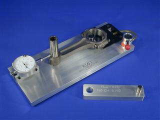
So you’ll need to install a piston, rod, pin, and bearings on the crank in the block and check the deck height. It can be done by independent calculations, by measuring each part and adding up the dimensions, but with small inconsistencies and tolerance stacking you will rarely come out perfectly. I find that calculation generally gets you within about .005Ë of the accurate measurement. By doing the pre-assembly, you can measure it all in place.
Be careful, though. Pistons are made using CNC machining operations that limit the pin height differences from one piston to the next to near zero. However, you should check your rods and pistons to make sure there are no differences in pin height or rod length over .005Ë total.
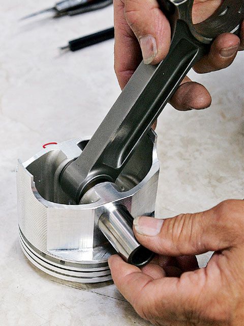
For a kit using full-floating pins, you can assemble the rod and piston using the included pins. However, if you have pressed pins, it requires using a modified pin. Shops that do custom work like Johnson Machine will have pins that have been turned down a couple thousandths so they will slide into both piston and rod – rather than press.
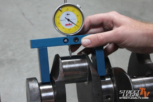
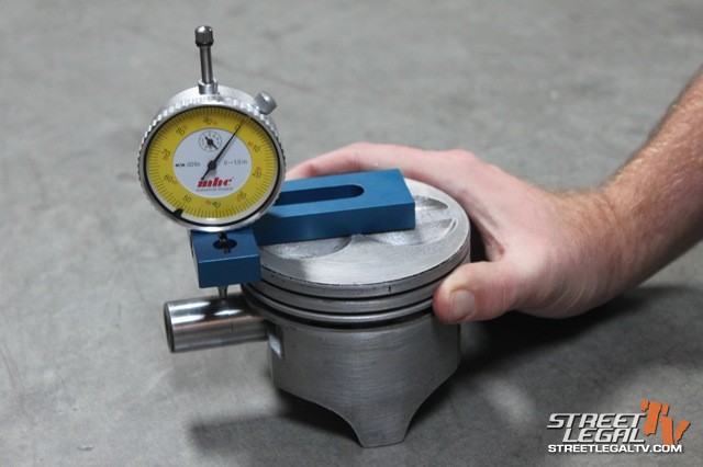
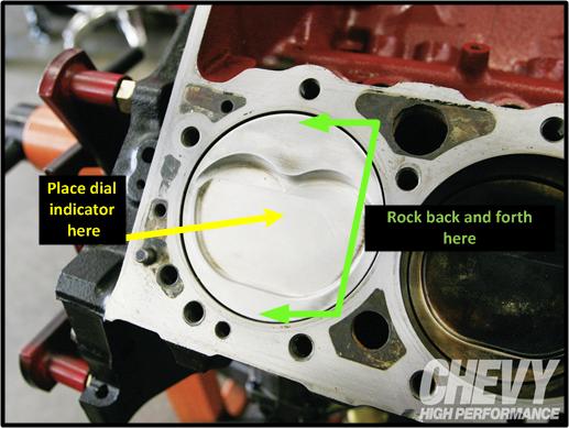
Once installed you need to bring the piston up to TDC. However, there is clearance between the bore and piston and you’ll see it rocks in the bore. To prevent this and prevent inconsistent measurements, Mike uses a couple of feeler gauge strips slid down on either side of the piston. Then he can set up the dial bore gauge and set it so it reads zero with the gauge pin resting on the block deck. Then, he swings the gauge over the piston and checks the difference. An alternative is to use a bridge micrometer or gauge.
Cam Clearance
In the old days and for custom strokers, one of the big concerns was that the cam would come into contact with the rods or crank. I know of no kit assemblies that have not been checked out before the first one got shipped to make sure this was not a problem. It is one of the best reasons to use stroker kits. In some cases there are machine operations that can solve this, but none are easy.
An example might be that the side of the big end of the rods or the rod bolt may contact the cam lobe. In some cases, you can shave the bolt or remove a little material from the rod to get clearance. Another might be where a counterweight on the crank gets into the cam. Here you can chuck the crank into a lathe and turn it down to get clearance. Remember that taking material off of any part of the rotating or reciprocating mass means changes in balance. This has meant adding Mallory metal and other balancing issues that can be pricey.
In any case, I’d make sure to ask before you lay down your cash if the supplier knows of any interference problems between the crank and block or rod to cam lobe. One answer would be that there are problems and they should also know what it takes to correct them. Another would be that they know there are no problems. The third is that they don’t know or don’t even know what that means. You may want to go elsewhere.
Crank Clearance
Mike’s favorite tool for finding crank interference problems is a large tie strap. These are about .050Ë thick and made from nylon so they are both durable and will not damage parts as he checks them. He installs the crank and then rotates it. If he finds a spot where it stops, he’ll identify where that is and what is the problem.
In the case of the build I witnessed, two of the counterweights were a little too large to clear the block. The crank would rotate, but the weights were so close they would trap the tie strap between block and crank. Mike figures if you don’t have at least .050Ë it’s too close.
As he works, Mike marks the areas where there is insufficient clearance with a black marker so changes can be made in the right places. Starting from one end and working step by step and inch by inch to the other, he looks for any place where the crank gets close to anything and identifies each.
To fix what he found in this instance, Mike asked Rex Eagleton to put the crank in the lathe and turn .050Ë from the two counterweights. Two areas, one large and one small, showed up when the crank was turned. By doing this work on the lathe you can cut all the high surfaces at once. By the way, it was also possible to have gone inside the block to machine out the contact areas instead of turning the crank, but that would have taken a lot more time, potentially weakening the block, and that just didn’t make a lot of sense in this case.
Rod and Piston
Although not likely in a kit assembly, I’ve seen where the bottom of the piston skirt would hit the crank. This can be fixed by milling the skirt at the affected area or turning the crank the same way. If you ever have to modify a piston, do so with care, remove only what’s needed, and be as consistent from one piston to the next as possible.
Because most kits have been pre-engineered to spec out pistons that do not have this problem, you may never need to deal with this, but it’s important that you know it’s possible and take a good hard look at it to make sure you don’t have something to fix. Mike again uses the tie strap to check it.
Other places to worry about are where the big end of the rod gets close to the bottom of the cylinder bore, where it gets close to the cam, or in some cases at the pan rail. Here again the cam clearance should have been verified or you should know any limits in lobe heights. The cam must be installed and degreed in to check clearances as small changes in rotation between the cam and other components can dramatically change clearance. The bottom of the bores and pan rails are routinely notched or relieved to get clearance. Another reason the tie strap works well is that it’s often hard to see or get your hands into these areas where the strap will slide right in. In other words, some of this is sight-oriented, but other areas are identified by feel.
You have to be careful where you remove material. There are areas where the casting is relatively thin and you can cut into the water jacket and then you really have trouble on your hands. If you are not absolutely sure of what is there to work with, you need to ask someone who has more experience or knowledge with your specific engine before you screw up.
Finally, each and every block, even the same size, year, and make, is unique. Castings change, there is the problem of core shift, and the original machining is not exactly the same from block to block. This means it’s up to you to take the time and either identify and correct or verify and pass each and every part of the short block. If you fail to do this or miss something you can grenade the entire thing and you’re gonna be left with a serious dent in your wallet. Obviously, the alternative is to have a pro like Mike do the job for you. It’s going to cost more that doing it yourself, but if you are not absolutely sure that you have it done and done right, it may be the best investment in your engine project you can make.
RELATED THREADS AND LINKS
http://garage.grumpysperformance.co...in-height-compression-height.5064/#post-69254
viewtopic.php?f=53&t=3759
http://www.musclemotorparts.com/comp_ht.htm
http://www.kb-silvolite.com/calc.php?action=piston_comp
http://www.kb-silvolite.com/calc.php?action=deck
http://www.bhjproducts.com/bhj_content/ ... ng/rlg.php
http://www.fordmuscle.com/fundamentals/ ... ndex.shtml
viewtopic.php?f=53&t=3759&p=9964#p9964
http://www.enginebuildermag.com/Content ... 019758.pdf
http://www.streetlegaltv.com/forum/all- ... -5156.html
Last edited by a moderator: