http://www.esabna.com/us/en/education/k ... ection.cfm
http://www.tregaskiss.com/hm/228/61/sel ... -wire-size
viewtopic.php?f=60&t=77
viewtopic.php?f=60&t=1669
viewtopic.php?f=60&t=10601
viewtopic.php?f=60&t=9745
the surface to be welded must be pre-cleaned with a wire brush,
down to clean rust free,
degreased, paint free, bare metal,must be well grounded and securely clamped
keep in mind youll need to find a local source for consumables like the MIG wire and plazma cutter components
it generally helps to make friends with the local welding supply counter guys and/or owner
these guys have a lot of experience and can provide tips youll need
lincoln and miller welding supply shops are generally helpful

http://www.airgas.com/category/Welding-Products-Filler-Metal-MIG-Wire-GMAW-SAW/_/N-0Z8ay
http://www.eastwood.com/blog/eastwood-chatter/10-tips-to-make-a-better-mig-weld/
http://www.rodauthority.com/tech-stories/welding-101-getting-started-with-mig-welding-basics/
http://garage.grumpysperformance.com/index.php?threads/links-for-welding-info.244/
http://garage.grumpysperformance.com/index.php?threads/good-source-for-welding-tips.530/
my old college engineering instructor used to say, in my welding shop
honestly I think he was correct, in that with a PROPERLY ADJUSTED MIG WELDER with the correct amps, wire , wire speed and gas shield flow rates the actual welding process is just not very difficult if your dealing with clean grease free metal surfaces, especially if your welding surface is not above you.
like most things, some time spent researching the subject and reading related books and watching a few related videos will tend to help out the newer guys considerably
http://reviews.ebay.com/Mig-Welder-Sele ... 0003813279
http://www.airgas.com/content/details.a ... 0000000143
http://www.airgas.com/content/details.a ... 0000000164
http://www.bakersgas.com/mig-shielding- ... guide.html
http://www.mig-welding.co.uk/tutorial.htm
http://www.hobartwelders.com/elearning/#mig
http://www.weldingtipsandtricks.com/mig ... icles.html
keeping mig wire rust free is the key, most quality mig wires lightly copper wash coated ,if your not using the spool in the welder for weeks at a time ,take it out, put it in a re-sealed 2 gallon zip lock plastic bag, laid on a couple sheets of paper towel with WD40 lightly sprayed on the towels, it will last for years sealed like that
heres a few tips
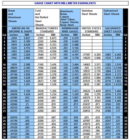
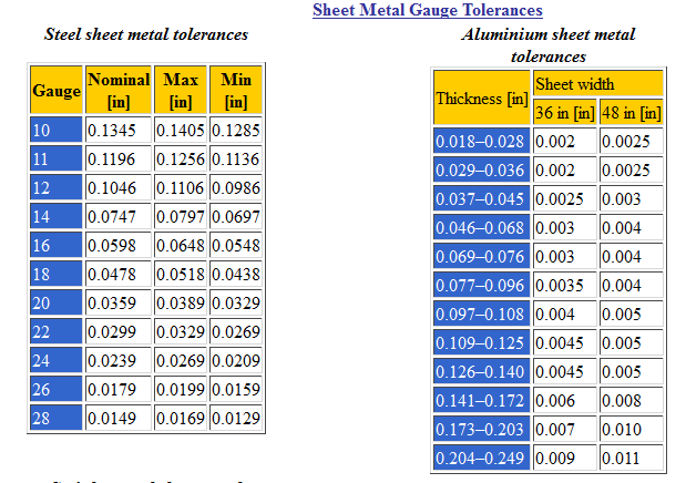
If you have a hard time judging MIG wire diameter or sheet metal gauges, they make a tool for that little issue in lack of judgmental skills
even the $20 import version is accurate enough for that use!
this link might be useful
http://www.engineersedge.com/gauge.htm
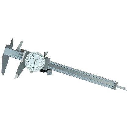
http://www.harborfreight.com/6-inch-dial-caliper-66541.html

An easy way to think of the two is this:
DC(-) Straight = more heat in the base metal (the metal melts faster)
DC(+) Reverse = more heat in the wire (the wire melts faster)
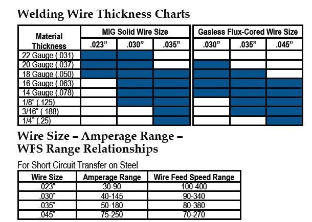
larger wire diam. takes more amps to melt and tends to result in more heat transfer to the area surrounding the weld, thinner wire tends to melt faster and impart a bit less heat to the surrounding area, obviously weld gun movement speed and wire feed speeds and amp settings can vary the results also, but smaller diam. wire tends to localize the heat to some extent, thats one reason youll tend to use thinner wire on thinner sheet steel as your going to use less average amps and less over all heat on a smaller area to generate the molten weld pool.
mig wire should be selected based on what your welding, a .025 wires great for sheet steel body parts and .030 makes a good compromise choice for both sheet metal body parts and thicker stuff up to about 3/16" thick.
youll usually get a better weld if your a bit too high on the amp setting than a bit too low, so if your not real sure try to keep it hot
most mig welders have a chart or a manual that gives suggested wire diam. feed speeds and amp ranges for different applications.
naturally you'll need to make adjustments to the wire feed mechanism if you change wire diam. and you'll need to keep the wire clean and dry to prevent corrosion.
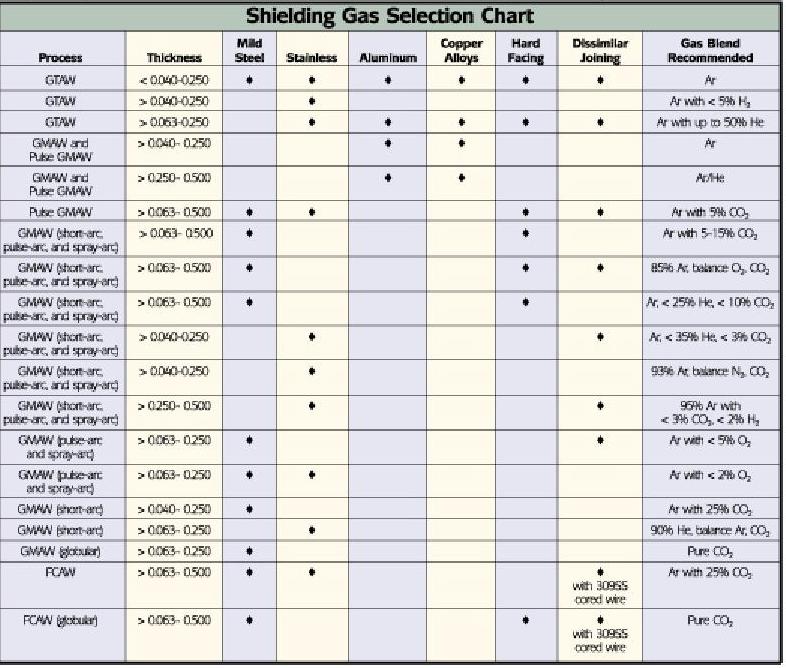
shield gas flow rates will also need to vary but 25 cubic feet per hour is a good basic rate to start with with a .030 wire most guys working on cars will use.
youll need a good die grinder and stiff stainless steel brush to clean potential weld surfaces of corrosion and paint.
beveling the edges of two parts to be welded where they will join tends to allow a better weld joint.
welding so the joint is directly down is obviously preferred, as hot molten metal tends to run with gravity, if working on a vertical surface joint working from the top down tends to leave a cleaner less bulged or protruding joint bead surface requiring less clean-up grinding,than working from the bottom upward.
tack welding thin metal joints in a stitch, skip, stitch pattern limits heat distortion
Making a Sound MIG Weld
The ability to make a good MIG weld is extremely important to the success of an auto repair technician. In fact, almost every welding repair made on a unibody car, light truck or van can be made with the Metal Inert Gas (MIG) welding process. For this reason, there are well-accepted standards and practices for producing sound MIG welds.
Note: This article is written for the person with a basic familiarity with welding who wants to practice and improve their welding technique. The process of arc welding poses several potential hazards that must be guarded. Therefore, all information relating to the safe operation of welding equipment and welding processes must be fully understood before attempting to begin work. Always read and follow the safety information in the operator's manual or contact the manufacturing company when in doubt.
What Needs Welding?
The front driver's side corner of a vehicle receives more damage than any other area. Parts damaged in this area include the upper rail, frame rail, radiator core support, and fender aprons. Other parts often damaged include the rear body panels, trunk floor, and lower rear rails. To make these repairs, the technician must thoroughly master all-position welding. It is important to practice so that you feel confident with making sound welds in all positions.
One way to become confident in your welding quality is to use a simple welding machine, such as the Millermatic® 185 from Miller Electric Mfg. Co. It comes complete with a package to get you started, including a 6 ft. power cord with plug, 10 ft. MIG gun and cable assembly, and 10 ft. work cable with heavy duty clamp. The package also includes a gas solenoid valve, flow gauge and 5 ft. gas hose, and factory installed running gear/cylinder rack.
Before making a repair weld, make test welds on material of the same type, thickness, and joint configuration. Visually inspect and destructively test the practice weld to ensure that it is sound before welding on the vehicle. Fine tuning the welding parameters and your technique on test welds improves the quality of the repair.
Welding In the Flat Position
For a flat joint, such as a butt joint, hold the gun at a 90 degree angle to the workpiece, directing the filler metal straight into the joint. A small, back and forth motion with the gun can help fill a large gap or when making multiple passes.
For a fillet weld on a T-joint, keep the gun at a 45 degree angle, or equal distance from each piece. When making multiple weld passes, the work angles change slightly. This helps avoid uneven weld beads and undercuts.
For a fillet weld on a lap joint, angle the gun between 60 and 70 degrees. The thicker the metal being welded, the greater the angle.
Plug welds should be made with the weld in the flat position if at all possible. Using a spiral-type technique, weld in a slow motion around the edges of the hole, making a complete circle before working toward the center (starting the spiral too soon can create pinholes). When welding around the edge, angle the gun slightly, somewhat like you would for a lap joint. Keep the gun perpendicular when filling the rest of the hole.
Horizontal
Because of the effects of gravity, the gun work angle must be dropped slightly by 0 to 15 degrees when welding horizontally. Without changing the work angle, the filler metal may sag or rollover on the bottom side of the weld joint. The travel angle, whether using a push or a drag technique, generally remains the same as for a weld joint in the flat position.
On thick metal when making multi-pass welds, or to bridge a slight gap where fit-up is poor, weave beads may be used to fill a weld joint. A back-and-forth weave, with or without a slight arch, is used in the horizontal position. A slight hesitation at the top toe of the weld helps prevent undercut and ensure proper tie-in of the weld to the base metal.
Voltage and amperage settings for welding in the horizontal position are usually the same, or very slightly less, than settings for welding in the flat position. However, note that if the wire diameter is too large, the resulting heat and size of the weld puddle may be too great to allow the weld puddle to freeze quickly, and the weld may rollover.
Vertical Positions
Vertical welding, both up and down, can be difficult. This makes pre-weld set-up very important for making high quality welds. Since you are fighting gravity, consider reducing the voltage and amperage 10 to 15 percent from the settings for the same weld in the flat position.
Know when to weld vertical down and when to weld vertical up. For vertical down welding, the welder begins at the top of a joint and welds down. This technique helps when welding thin metals because the arc penetrates less due to the faster travel speed. Because vertical down welding helps avoid excessive melt-through, welders sometimes place very thin materials in the vertical position even if they can weld them in the flat position.
When welding vertical down, angle the gun slightly back into the weld puddle at a 5 to 15 degree angle. For thin metal where burn-through is a concern, angle the gun slightly up and pull it downward (i.e., direct the wire away from the weld puddle). Either way, keep the electrode wire on the leading edge of the weld puddle. A very slight weave may help flatten the weld crown.
The vertical up technique - beginning at the bottom of a joint and welding up - can provide better penetration on thicker materials (typically 1/4 in. or more). The travel angle of the gun is a 5 to 15 degree drop from the perpendicular position. A slight weaving motion can help control the size, shape and cooling effects of the weld puddle.
Making a plug weld in the vertical position is somewhat similar to making a vertical up fillet weld. For a vertical plug weld, the filler metal is deposited upward along one side of the hole. Then, another bead is deposited from the bottom to the top on the other side of the hole. Alternate sides until the hole is filled. For thin metal, use a similar technique, but weld in the vertical down position to prevent burn-through.
Overhead Position
Drag, push or perpendicular gun techniques can be used for welding overhead. But, because of gravity, travel speeds must be fast enough so that the weld metal does not fall out of the joint. Also for this reason, weave beads should not be too wide. Using smaller diameter electrodes (e.g., .023 in.) and lowering the voltage and amperage help keep the weld puddle small and more controllable, too.
Work angles and travel angles for the overhead position can be thought of as the same angles for the flat position, only upside down. However, be sure to keep the gun nozzle clean, as spatter can build up much faster when overhead welding. Also, because the shielding gas flows upward, you may have to increase the gas flow rate to ensure proper coverage.
Travel Speed and Stickout
Travel speed and electrode extension (or stickout) also influence the shape and quality of a weld bead to a significant degree. Travel speed is the rate at which you move the gun along the joint. Many experienced MIG welders can determine the correct travel speed by judging the weld puddle size - in relation to the joint thickness - and keeping the arc on the leading edge of the puddle.
Stickout is the length of unmelted electrode extending from the tip of the contact tube. Changing the stickout - which occurs with variations in the distance of the contact tube to the workpiece - causes the voltage and amperage to vary, as well as changes the shape of the weld bead.
Generally, maintain a stickout of 1/4 to 1/2 in. Note that when starting a weld, a short stickout helps ensure a good, hot start; a longer stickout - once you've established the arc - can help bridge a gap when encountering poor fit-up. [Note: Long stickouts promote poor starts.] For critical welds, maintain a constant stickout.
More Practice
To make a sound weld, you must learn to combine the mechanical techniques noted in this article into one fluid welding motion. Practice so that welding on all joints in all positions becomes second nature.
For more information on Miller Electric and its MIG welding products, call 1-800-4-A-Miller (1-800-426-4553) or visit the website at http://www.MillerWelds.com.
Miller's 142-page Gas Metal Arc Welding handbook provides a comprehensive, yet easy to read, explanation of the GMAW, or MIG, process. It contains detailed instructions on how to set up MIG equipment, set MIG variables, select the correct shielding gas, welding techniques, safety, and troubleshooting. Cost is $25. Call Miller at (920) 735-4356 and ask for publication #151 682, Gas Metal Arc Welding
http://www.tregaskiss.com/hm/228/61/sel ... -wire-size
viewtopic.php?f=60&t=77
viewtopic.php?f=60&t=1669
viewtopic.php?f=60&t=10601
viewtopic.php?f=60&t=9745
the surface to be welded must be pre-cleaned with a wire brush,
down to clean rust free,
degreased, paint free, bare metal,must be well grounded and securely clamped
keep in mind youll need to find a local source for consumables like the MIG wire and plazma cutter components
it generally helps to make friends with the local welding supply counter guys and/or owner
these guys have a lot of experience and can provide tips youll need
lincoln and miller welding supply shops are generally helpful
http://www.airgas.com/category/Welding-Products-Filler-Metal-MIG-Wire-GMAW-SAW/_/N-0Z8ay
http://www.eastwood.com/blog/eastwood-chatter/10-tips-to-make-a-better-mig-weld/
http://www.rodauthority.com/tech-stories/welding-101-getting-started-with-mig-welding-basics/
http://garage.grumpysperformance.com/index.php?threads/links-for-welding-info.244/
http://garage.grumpysperformance.com/index.php?threads/good-source-for-welding-tips.530/
my old college engineering instructor used to say, in my welding shop
We can teach monkeys to MIG weld so I assume theres SOME FAINT HOPE for you gentlemen"
honestly I think he was correct, in that with a PROPERLY ADJUSTED MIG WELDER with the correct amps, wire , wire speed and gas shield flow rates the actual welding process is just not very difficult if your dealing with clean grease free metal surfaces, especially if your welding surface is not above you.
like most things, some time spent researching the subject and reading related books and watching a few related videos will tend to help out the newer guys considerably
http://reviews.ebay.com/Mig-Welder-Sele ... 0003813279
http://www.airgas.com/content/details.a ... 0000000143
http://www.airgas.com/content/details.a ... 0000000164
http://www.bakersgas.com/mig-shielding- ... guide.html
http://www.mig-welding.co.uk/tutorial.htm
http://www.hobartwelders.com/elearning/#mig
http://www.weldingtipsandtricks.com/mig ... icles.html
keeping mig wire rust free is the key, most quality mig wires lightly copper wash coated ,if your not using the spool in the welder for weeks at a time ,take it out, put it in a re-sealed 2 gallon zip lock plastic bag, laid on a couple sheets of paper towel with WD40 lightly sprayed on the towels, it will last for years sealed like that
heres a few tips
If you have a hard time judging MIG wire diameter or sheet metal gauges, they make a tool for that little issue in lack of judgmental skills
even the $20 import version is accurate enough for that use!
this link might be useful
http://www.engineersedge.com/gauge.htm
http://www.harborfreight.com/6-inch-dial-caliper-66541.html
An easy way to think of the two is this:
DC(-) Straight = more heat in the base metal (the metal melts faster)
DC(+) Reverse = more heat in the wire (the wire melts faster)
larger wire diam. takes more amps to melt and tends to result in more heat transfer to the area surrounding the weld, thinner wire tends to melt faster and impart a bit less heat to the surrounding area, obviously weld gun movement speed and wire feed speeds and amp settings can vary the results also, but smaller diam. wire tends to localize the heat to some extent, thats one reason youll tend to use thinner wire on thinner sheet steel as your going to use less average amps and less over all heat on a smaller area to generate the molten weld pool.
mig wire should be selected based on what your welding, a .025 wires great for sheet steel body parts and .030 makes a good compromise choice for both sheet metal body parts and thicker stuff up to about 3/16" thick.
youll usually get a better weld if your a bit too high on the amp setting than a bit too low, so if your not real sure try to keep it hot
most mig welders have a chart or a manual that gives suggested wire diam. feed speeds and amp ranges for different applications.
naturally you'll need to make adjustments to the wire feed mechanism if you change wire diam. and you'll need to keep the wire clean and dry to prevent corrosion.
shield gas flow rates will also need to vary but 25 cubic feet per hour is a good basic rate to start with with a .030 wire most guys working on cars will use.
youll need a good die grinder and stiff stainless steel brush to clean potential weld surfaces of corrosion and paint.
beveling the edges of two parts to be welded where they will join tends to allow a better weld joint.
welding so the joint is directly down is obviously preferred, as hot molten metal tends to run with gravity, if working on a vertical surface joint working from the top down tends to leave a cleaner less bulged or protruding joint bead surface requiring less clean-up grinding,than working from the bottom upward.
tack welding thin metal joints in a stitch, skip, stitch pattern limits heat distortion
Making a Sound MIG Weld
The ability to make a good MIG weld is extremely important to the success of an auto repair technician. In fact, almost every welding repair made on a unibody car, light truck or van can be made with the Metal Inert Gas (MIG) welding process. For this reason, there are well-accepted standards and practices for producing sound MIG welds.
Note: This article is written for the person with a basic familiarity with welding who wants to practice and improve their welding technique. The process of arc welding poses several potential hazards that must be guarded. Therefore, all information relating to the safe operation of welding equipment and welding processes must be fully understood before attempting to begin work. Always read and follow the safety information in the operator's manual or contact the manufacturing company when in doubt.
What Needs Welding?
The front driver's side corner of a vehicle receives more damage than any other area. Parts damaged in this area include the upper rail, frame rail, radiator core support, and fender aprons. Other parts often damaged include the rear body panels, trunk floor, and lower rear rails. To make these repairs, the technician must thoroughly master all-position welding. It is important to practice so that you feel confident with making sound welds in all positions.
One way to become confident in your welding quality is to use a simple welding machine, such as the Millermatic® 185 from Miller Electric Mfg. Co. It comes complete with a package to get you started, including a 6 ft. power cord with plug, 10 ft. MIG gun and cable assembly, and 10 ft. work cable with heavy duty clamp. The package also includes a gas solenoid valve, flow gauge and 5 ft. gas hose, and factory installed running gear/cylinder rack.
Before making a repair weld, make test welds on material of the same type, thickness, and joint configuration. Visually inspect and destructively test the practice weld to ensure that it is sound before welding on the vehicle. Fine tuning the welding parameters and your technique on test welds improves the quality of the repair.
Welding In the Flat Position
For a flat joint, such as a butt joint, hold the gun at a 90 degree angle to the workpiece, directing the filler metal straight into the joint. A small, back and forth motion with the gun can help fill a large gap or when making multiple passes.
For a fillet weld on a T-joint, keep the gun at a 45 degree angle, or equal distance from each piece. When making multiple weld passes, the work angles change slightly. This helps avoid uneven weld beads and undercuts.
For a fillet weld on a lap joint, angle the gun between 60 and 70 degrees. The thicker the metal being welded, the greater the angle.
Plug welds should be made with the weld in the flat position if at all possible. Using a spiral-type technique, weld in a slow motion around the edges of the hole, making a complete circle before working toward the center (starting the spiral too soon can create pinholes). When welding around the edge, angle the gun slightly, somewhat like you would for a lap joint. Keep the gun perpendicular when filling the rest of the hole.
Horizontal
Because of the effects of gravity, the gun work angle must be dropped slightly by 0 to 15 degrees when welding horizontally. Without changing the work angle, the filler metal may sag or rollover on the bottom side of the weld joint. The travel angle, whether using a push or a drag technique, generally remains the same as for a weld joint in the flat position.
On thick metal when making multi-pass welds, or to bridge a slight gap where fit-up is poor, weave beads may be used to fill a weld joint. A back-and-forth weave, with or without a slight arch, is used in the horizontal position. A slight hesitation at the top toe of the weld helps prevent undercut and ensure proper tie-in of the weld to the base metal.
Voltage and amperage settings for welding in the horizontal position are usually the same, or very slightly less, than settings for welding in the flat position. However, note that if the wire diameter is too large, the resulting heat and size of the weld puddle may be too great to allow the weld puddle to freeze quickly, and the weld may rollover.
Vertical Positions
Vertical welding, both up and down, can be difficult. This makes pre-weld set-up very important for making high quality welds. Since you are fighting gravity, consider reducing the voltage and amperage 10 to 15 percent from the settings for the same weld in the flat position.
Know when to weld vertical down and when to weld vertical up. For vertical down welding, the welder begins at the top of a joint and welds down. This technique helps when welding thin metals because the arc penetrates less due to the faster travel speed. Because vertical down welding helps avoid excessive melt-through, welders sometimes place very thin materials in the vertical position even if they can weld them in the flat position.
When welding vertical down, angle the gun slightly back into the weld puddle at a 5 to 15 degree angle. For thin metal where burn-through is a concern, angle the gun slightly up and pull it downward (i.e., direct the wire away from the weld puddle). Either way, keep the electrode wire on the leading edge of the weld puddle. A very slight weave may help flatten the weld crown.
The vertical up technique - beginning at the bottom of a joint and welding up - can provide better penetration on thicker materials (typically 1/4 in. or more). The travel angle of the gun is a 5 to 15 degree drop from the perpendicular position. A slight weaving motion can help control the size, shape and cooling effects of the weld puddle.
Making a plug weld in the vertical position is somewhat similar to making a vertical up fillet weld. For a vertical plug weld, the filler metal is deposited upward along one side of the hole. Then, another bead is deposited from the bottom to the top on the other side of the hole. Alternate sides until the hole is filled. For thin metal, use a similar technique, but weld in the vertical down position to prevent burn-through.
Overhead Position
Drag, push or perpendicular gun techniques can be used for welding overhead. But, because of gravity, travel speeds must be fast enough so that the weld metal does not fall out of the joint. Also for this reason, weave beads should not be too wide. Using smaller diameter electrodes (e.g., .023 in.) and lowering the voltage and amperage help keep the weld puddle small and more controllable, too.
Work angles and travel angles for the overhead position can be thought of as the same angles for the flat position, only upside down. However, be sure to keep the gun nozzle clean, as spatter can build up much faster when overhead welding. Also, because the shielding gas flows upward, you may have to increase the gas flow rate to ensure proper coverage.
Travel Speed and Stickout
Travel speed and electrode extension (or stickout) also influence the shape and quality of a weld bead to a significant degree. Travel speed is the rate at which you move the gun along the joint. Many experienced MIG welders can determine the correct travel speed by judging the weld puddle size - in relation to the joint thickness - and keeping the arc on the leading edge of the puddle.
Stickout is the length of unmelted electrode extending from the tip of the contact tube. Changing the stickout - which occurs with variations in the distance of the contact tube to the workpiece - causes the voltage and amperage to vary, as well as changes the shape of the weld bead.
Generally, maintain a stickout of 1/4 to 1/2 in. Note that when starting a weld, a short stickout helps ensure a good, hot start; a longer stickout - once you've established the arc - can help bridge a gap when encountering poor fit-up. [Note: Long stickouts promote poor starts.] For critical welds, maintain a constant stickout.
More Practice
To make a sound weld, you must learn to combine the mechanical techniques noted in this article into one fluid welding motion. Practice so that welding on all joints in all positions becomes second nature.
For more information on Miller Electric and its MIG welding products, call 1-800-4-A-Miller (1-800-426-4553) or visit the website at http://www.MillerWelds.com.
Miller's 142-page Gas Metal Arc Welding handbook provides a comprehensive, yet easy to read, explanation of the GMAW, or MIG, process. It contains detailed instructions on how to set up MIG equipment, set MIG variables, select the correct shielding gas, welding techniques, safety, and troubleshooting. Cost is $25. Call Miller at (920) 735-4356 and ask for publication #151 682, Gas Metal Arc Welding
Last edited by a moderator: