multi-meters

grumpyvette

Administrator
Staff member
http://www.ladyada.net/learn/multimeter/

http://www.multimeterwarehouse.com/usingamultimeter.htm

http://www.wikihow.com/Use-a-Multimeter

http://mechatronics.mech.northwestern.e ... meter.html

viewtopic.php?f=80&t=728&p=9217#p9217

http://garage.grumpysperformance.co...-auto-elecrtrical-connectors.3105/#post-68805

http://www.acmehowto.com/howto/homemain ... teruse.php

viewtopic.php?f=70&t=3901&p=10343&hilit=multi+meter#p10343

http://www.harborfreight.com/ac-dc-digi ... 37772.html

http://www.summitracing.com/parts/ESI-501/
esi-501_w.jpg


don,t forget a assortment of test leads

http://www.testpath.com/Categories/Test ... g-3246.htm

http://www.bipom.com/documents/e_z_hook/XJXJLLeads.pdf

http://www.picoauto.com/automotive-test-leads.html


having a wide assortment of different multi meter test leads available is a huge benefit while testing
the clip test leads that test thru a wires insulation without much damage are a big help


693Pred.jpg

bedtest1.jpg

bedtest2.jpg

bedtest3.jpg
 
Last edited by a moderator:
C4 Sensor Check Information
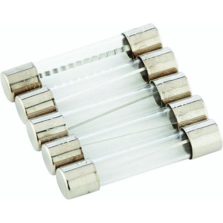
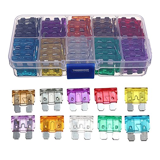
first check your shop manual for the fuse and fuse able link locations
fuses are located in several locations and fuse-able links near the battery

READ THRU THESE THREADS ALSO


https://www.amazon.com/DEPSTECH-Wat...ocphy=9012039&hvtargid=pla-469718487357&psc=1

The C4 Corvette makes use of numerous sensors that feed information to the ECM/PCM (Electronic Control Module / Powertrain Control Module) and to the instruments on the dashboard.

Even if the sensor is operated by vacuum or pressure, the output is converted into an electrical signal for processing by the ECM. Most faulty sensors will cause a trouble code to be set (resulting in a 'Check Engine/SYS ' Light) and also alter the performance of the automobile. When troubleshooting the reason for the code, the normal approach is to go straight to the sensor and assume that it is faulty. While this may be the normal practice, you are strongly cautioned that it is seldom the sensor but rather a connector, a power problem or a grounding issue that is actually causing the problem. Or, the sensor may simply be doing it's job and reporting an occurrence that is at variance with what is allowed or expected by the ECM/PCM. In any event, because the sensor really is the easiest thing to check, the following information is provided to assist you in determining if the device is operating properly.

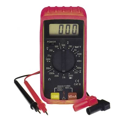
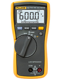
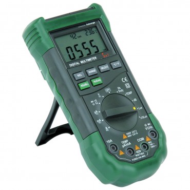
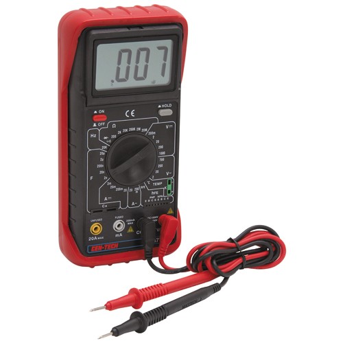
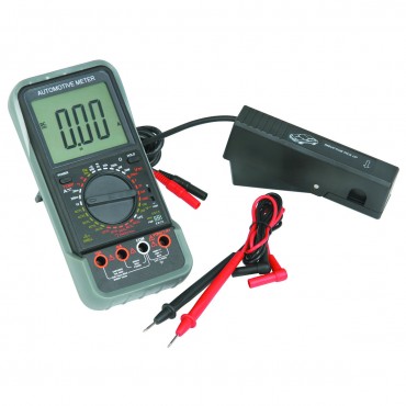
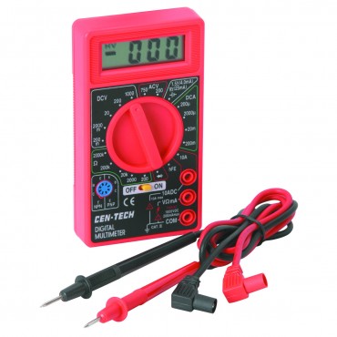
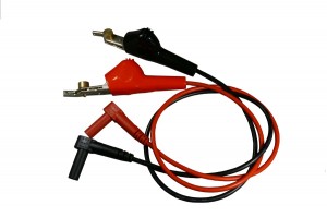
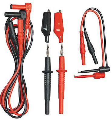
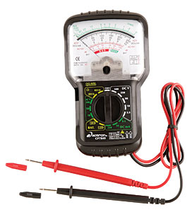
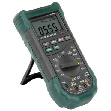
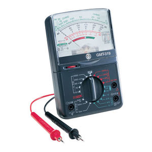
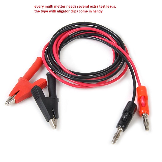
You will need a D-VOM (Digital Volt-Ohm Meter) to check the items below. It should have at least a10 megohms per volt rating, something that will be shown in the specifications. For those sensors listed below that have ohms listed as the measurement item, disconnect the negative battery terminal and then the sensor harness connector and measure the sensor's terminals. For voltage measurements, you can obtain test harnesses from any of the Corvette specialty catalog houses. [Before beginning your efforts, print the page so you can cross reference the code information with the sensor information.]

Sensor Location Measured Value
Engine Coolant Temperature Sensor. Front of engine, below Throttle Body. 185 Ohms @ 210F, 3400 Ohms @ 68F, 7,500 Ohms @ 39 F.
Engine Oil Temperature Sensor. Left rear of engine, just above the oil filter. 185 Ohms @ 210 F, 3400 Ohms @ 68 F, 7,500 Ohm @39 F.
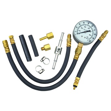
Oil Pressure Sender/Switch. Top, left hand rear of engine. 1 Ohms @ 0 PSI, 43 Ohms @ 30 PSI, 86 Ohms @ 6PSI.
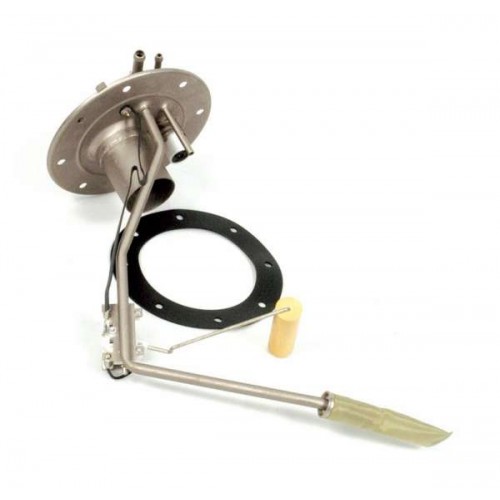
Fuel Quantity Sender. Top of fuel tank, beneath filler pipe escutcheon panel. 0 Ohms @ Empty, 45 Ohms @ 1/2 Full, 90 Ohms @ Full.
MAT (Manifold Absolute Temperature Sensor). Underside of manifold air plenum at rear. 185 Ohms @ 210 F, 3400 Ohms @ 70 F, 15,000 Ohms @ 40 F.
Outside Temperature Sensor. Right side of engine, top right corner of radiator. 4400 Ohms @ 60 F, 2200 Ohms @ 85 F.
In Car Temp Temperature Sensor. Coupe: above left seat near interior courtesy light, Convertible: center of cargo compartment lid. 4400 Ohms @ 60 F, 2200 Ohms @ 85 F.
MAF (Mass Air Flow) Sensor. Front of engine ahead of throttle body. .4 Volts @ idle, 5 Volts @ Full Throttle.
Oxygen (O2) Sensor. Left side of engine, in exhaust pipe. .1 Volt Lean Mixture, .9 Volt Rich Mixture.
TPS (Throttle Position Sensor). Right side of throttle body at the front. .54 Volts Idle, ~ 5 Volts Full Throttle.
Assembly Line Communications Link (ALCL)
F E D C B A
G H J K L M
[The ALCL is located underneath the dashdoard, just below the instrument panel and left of center console.]
Top of page
Code Circuit or Sensor Possible Failures
13 Oxygen Sensor Circuit Check wiring and connectors. Bad Sensor
14 Coolant Sensor Circuit (High) Check wiring, connectors, thermostat. Monitor actual engine temperature. If within limits, and wiring and connector is OK, change thermostat and or sensor.
15 Coolant Sensor Circuit (Low) See above, particularly thermostat
16 Ignition Problems (Used only on 1992-1996 models) Direct Ignition (DI) Fault
21 Throttle Position Sensor (TPS) (High) Sticking or Misadjusted TPS. Also check wiring and connectors. Adjust or replace TPS.
22 Throttle Position Sensor (TPS) (Low) Sticking or Misadjusted TPS. Also check wiring and/ connectors. Adjust or Replace TPS.
23 Intake Air Temperature (Low) Measure sensor resistance with Digital Ohm meter. Must not be 0 ohms or infinite ohms. Replace if it shows one of these readings. Check wiring and/ connector of sensor. If OK, replace sensor.
24 Vehicle Speed Sensor (VSS) Only valid if vehicle moving. Check connections at ECM Check TPS setting. Possible ECM failure.
25 Intake Air Temperature (High) Measure sensor resistance with Digital Ohm meter. Must not be 0 ohms or infinite ohms. Replace if it shows one of these readings. Check wiring and connector of sensor OK.
26 Quad Driver Module Number 1 Check EGR, Canister Purge and AIR pump relays with a digital Ohm meter. A resistance of less than 18 ohms indicates a bad relay. If OK, potential ECM failure.
27 Quad Driver Module Number 2 Potential ECM or on a manual transmission car, potential upshift relay problem. Check relay, replace if less than 18 Ohms using a digital Ohm Meter.
28 Quad Driver Module Number 3 Air conditioning Clutch relay and/or cooling fan relays. Check with digital Ohm meter, replace if less than 18 Ohms. If relays OK, potential ECM failure.
32 Exhaust Gas Recirculation Circuit The most common cause of this code is a bad or intermittent EGR switch which is located on the EGR pipe between the exhaust manifold and the intake manifold. Replace this switch first when you get this code. Next, check electrical connections at EGR valve solenoid and then the ECM. Check all vacuum lines for leaks especially around the EGR valve. Possible ECM failure.
33 Mass Air Flow Sensor Circuit (1985-1990) Inspect intake system for leaks, Inspect for vacuum leaks, Check MAF connector and wiring, Check MAF for open using digital Ohm meter. Possible ECM failure.
33 Manifold Absolute Pressure High (1984) Check vacuum hoses. Check wiring to sensor. Change sensor. Check connections at ECM.
34 Mass Air Flow Circuit (1985-1990) Clean the throttle body. Check MAF connections. Replace MAF relay. Replace MAF Sensor. Possible ECM failure.
34 Manifold Absolute Pressure Low (1984) Check Vacuum hoses associated with MAP sensor. Check wiring and connections, particularly at ECM. Replace the sensor. Possible ECM failure.
35 Idle Air Control Circuit (IAC) Check fuel pressure, injectors, leaking throttle body. Change the IAC valve.
36 Mass Air Flow Burn Off Circuit Check connections at MAF, MAF relay and MAF Burn off relay. Check resistance of MAF relay and MAF burnoff relay with digital Ohm meter. replace if less than 18 Ohms. Possible ECM failure.
41 Cylinder Select Error Circuit (1985-1991) Check wiring at ECM. Possible PROM failure, or incorrectly seated PROM. Reseat PROM. Possible ECM failure.
42 Electronic Spark Timing Circuit (EST) Check wiring at ignition module. Replace ignition module. Possible ECM failure.
43 Knock Sensor Circuit Check ECM wiring. Replace knock sensor
44 Lean Exhaust Present Check wiring.connectors at Oxygen sensor. Check fuel pressure. Replace Oxygen sensor.
45 Rich Exhaust Present Check evaporation charcoal canister for smell of fuel (which normally comes from filling fuel tank to full). check fuel pressure regulator. Possible leaking fuel injector or sticking/bad EGR valve. Possible bad Oxygen sensor.
46 VATS Anti Theft Circuit Fault With negative battery lead disconnected and using high pressure, non residue contact spray cleaner, spray into area where ignition key inserts followed by inserting and removing key several times. Check for open/short on harness from steering column VATS ignition key to ECM. Possible defective anti-theft module.
51 PROM/EEPROM Error Faulty or incorrect PROM in the ECM. Change PROM with correct version for automobile.
52 Oil Temperature Circuit (Low Temperature) Check connections at the oil temperature switch. If OK, replace switch.
53 System Charging Voltage High or Low If voltage is more than 17.1 or less than 10 volts, this code will be set.Check battery leads, alternator drive belt for tightness and have electrical shop check alternator output. Voltage with engine off should be 12 volts. Voltage with engine running should be 14-15 volts. Use digital volt meter for checks and measure at the battery terminals.
54 Fuel Pump Circuit (Low Voltage) Using digital Ohm meter, check fuel pump circuits for shorts or opens.
55 Engine Running Lean This code is set when there is not enough fuel when accelerating. A possible fuel pump failure or insufficient fuel pressure due to a fuel line restriction is indicated.
62 Oil Temperature Circuit (High Temperature) Check wiring associated with Oil temperature switch. Replace switch.
63 Oxygen Sensor Circuit (Open) Check wiring and connections to Oxygen sensor.
64 Oxygen Sensor Circuit (Lean Exhaust) Check wiring and connections from Oxygen sensor to ECM. Check ECM ground terminal and battery ground. Check fuel pressure and fuel pump. Replace Oxygen sensor if all of above OK.
65 Oxygen Sensor Circuit (Rich Exhaust) Check evaporative charcoal canister for fuel fumes. Replace if contaminated. Check oil for presence of fuel. Check fuel pressure regulator, fuel pump, check for leaking injectors, Check for stuck/defective EGR valve, Replace Oxygen sensor if all above OK.
66 Air Conditioner Pressure Limit Exceeded Check the sensor electrical terminal connections and possible short to ground or open circuit in the pressure senor circuit senor wiring. Replace the Air Conditioning Refrigerant sensor.
67 Air Conditioner Pressure Limit Exceeded Check the pressure sensor or air conditioning clutch ciruit for possible short to ground or open circuit pressure sensor circuit in the sensor wiring.Replace the Air Conditioning Refrigerant sensor.
68 Air Conditioner Relay Fault Check the air conditioning relay circuit and the relay for possible short to ground or open circuit.
69 Air Conditioner Clutch Fault Check the air conditioning clutch circuit and the relay for possible short to ground or open circuit.
72 Gear Selector Switch Fault (Start Lockout) Check the connections at the TCC solenoid and Park Neutral switch. Replace the ECM or repair the transmission as needed.
[Info taking form 1984 thur 1996 Haynes Repair Manual]
 
Last edited by a moderator:
meters come in really handy when diagnosing many electrical sensors
like this


15 - Coolant Sensor Circuit - Excessive Low temperature indicated


To test the coolant sensor, unplug the wire connector and test the resistance across the two terminals of the SENSOR with an ohm meter.

The sensor screws into the intake manifold, on the front passenger side, by the thermostat housing.

Coolant sensor approximate resistance specifications:
177 ohms @ 212 deg. F. or 100 deg. C.
241 ohms @ 194 deg. F. or 90 deg. C.
332 ohms @ 176 deg. F. or 80 deg. C.
467 ohms @ 158 deg. F. or 70 deg. C.
667 ohms @ 140 deg. F. or 60 deg. C.
973 ohms @ 122 deg. F. or 50 deg. C.
1188 ohms @ 113 deg. F. or45 deg. C.
1459 ohms @ 104 deg. F. or 40 deg. C.
1802 ohms @ 95 deg. F. or 35 deg. C.
2238 ohms @ 86 deg. F. or 30 deg. C.
2796 ohms @ 77 deg. F. or 25 deg. C.
3520 ohms @ 68 deg. F. or 20 deg. C.
4450 ohms @ 59 deg. F. or 15 deg. C.
5670 ohms @ 50 deg. F. or 10 deg. C.
7280 ohms @ 41 deg. F. or 5 deg. C.
9420 ohms @ 32 deg. F. or 0 deg. C.
12300 ohms @ 23 deg. F. or -5 deg. C.
16180 ohms @ 14 deg. F. or -10 deg. C.
21450 ohms @ 5 deg. F. or -15 deg. C.
28680 ohms @ -4 deg. F. or -20 deg. C.
52700 ohms @ -22 deg. F. or -30 deg. C.
100700 ohms @ -40 deg. F. or - 40 deg. C.


these links may help

http://autospeed.com/cms/A_110895/artic ... larArticle

viewtopic.php?f=80&t=728&p=9217&hilit=sensor#p9217

http://www.8886.co.uk/ref/ohm_meter.htm

http://www.wikihow.com/Use-an-Ohmmeter

http://www.wikihow.com/Use-a-Multimeter

http://www.ladyada.net/learn/multimeter/

http://www.acmehowto.com/howto/homemain ... teruse.php


http://tpiparts.net/90_92_speed_density_sensors/

http://tpiparts.net/85_89_maf_sensors/
 
as most of us who work on cars know chasing minor electrical glitches is a P.I.T.A. and it helps a good deal to have at least a minimal quality multi meter and test leads, and a scan tool, that can be used to, locate isolate and test THRU insulation on wires, and a tool to pull trouble codes and do minimal programing.

21JGPEK8GVL._SS400_.jpg

this looks interesting with a discount coupon its discounted to about $169.99 until 4/30/18 plus $49.99 for a two year 100% warranty

http://garage.grumpysperformance.co...pro-scanner-harbor-freight-zurich-zr13.14833/


if you purchase a ZR13 auto code scanner, from HF,
you need this info
DOWN-LOAD AND PRINT IT OUT!


https://manuals.harborfreight.com/manuals/63000-63999/Q63806.pdf

https://manuals.harborfreight.com/manuals/63000-63999/63806.pdf


digitalsavings_08.png

https://www.harborfreight.com/catalogsearch/result/index/?dir=asc&order=EAScore,f,EAFeatured+Weight,f,Sale+Rank,f&q=zr13
zr13sc.png

zr13sc1.png


Last edited: Oct 14, 2018


http://www.amazon.com/AutoXray-6000-EZ- ... cr_pr_pb_t

F-113_01a_c_200.jpg

http://www.fluke.com/Fluke/usen/Digital ... ?PID=55990

image_12926.jpg

http://www.harborfreight.com/5-in-1-dig ... 98674.html

image_493.jpg

http://www.harborfreight.com/ac-dc-digi ... 37772.html

image_13487.jpg

http://www.harborfreight.com/lcd-automo ... 95670.html

image_11746.jpg

http://www.harborfreight.com/7-function ... 90899.html
these last pictured red bargain meters are WORTHLESS in my opinion, they seldom work or work long, or give consistent info


YES YOU ABSOLUTELY NEED TWO SETS OF THESE LEADS, WITH ANY MULTI METER
bon2.jpg

bon3.jpg

bon1.jpg

bon5.png

http://www.ast-labs.com/shop/cable_alli ... Mgodzj0ADQ
 
Last edited by a moderator:
100%chevy posted this bit of info
"if an electric motor blows the breaker check the capacitor,(s)
do you have a multi-meter?
If so,unplug the compressor.
Un-cover the capacitors.
Take a good insulated screwdriver and carefully short the capacitor terminals to ground.All of them!
Once you do this,the charge is gone.
Now,set the meter on resistance(pick one,you may have to try other settings)and put one probe on each of the capacitor terminals.Do one capacitor at a time.If you get nothing,reverse the leads.
If the meter is set on the right range and you have the polarity right,the scale should jump up to almost full scale and slowly go back down.
If not,the capacitor is bad.
Some motors have 1 cap and some have 2.Some motors also may have a centrifugal switch on the end of the motor.This switch switches the windings from start to run.
Sometimes,inside the connection cover on the end of the motor,you may find the terminals burned.On either side of the little board.
Might be the un-loader or check valve is stuck,not letting off the head pressure or allowing air to go in the tank.
Plug it in as close as possible to the breaker and you may need to try a different breaker."


btw DIGITAL MULTI METER ARE NOT VERY USEFUL CHECKING CAPACITORS, the OLDER ANALOG VERSIONS TEND TO WORK BETTER FOR THIS TEST
IM JUST CURIOUS?
how many of you gentlemen go to a computer, print out related wiring diagrams ,get out a multi meter and a shop manual and actually read the shop manual, and step thru the indicated testing procedures? check for voltage ohms resistance, loose connections, etc. and have actually used the shop manual, multi meter and printed wiring diagrams ans instructions to isolate and solve a problem on your car?

these work for most tests, but not ideal for a capacitor

http://www.harborfreight.com/5-in-1-dig ... 98674.html


this type is far easier to test capacitors with
885-CP7849.jpg

if you purchase a ZR13 auto code scanner, from HF,
you need this info
DOWN-LOAD AND PRINT IT OUT!
https://manuals.harborfreight.com/manuals/63000-63999/Q63806.pdf

https://manuals.harborfreight.com/manuals/63000-63999/63806.pdf

zr13sc.png

zr13sc1.png

all the answers are readily available, theres known testing procedures and listed test results you can expect, and procedures listed in the shop manual for isolating and testing components, you don,t need to be a genius, you just need to be logical and persistent and not afraid to learn new things while getting your hands dirty at times, don,t get overwhelmed , break everything down too easy individual problems and tests, verify and test all the sensors,and test for factors like consistent fuel pressure, known temps,expected voltage or ohms resistance, and vacuum readings and don,t randomly start replacing parts as that gets expensive and its rarely the most efficient way to eliminate problems(unless you get really lucky) with modern computer diagnostic software you,ll have some advantages but think logically, most automotive problems still concern, loose electrical connectors, defective sensors, lack of compression, fuel delivery issues ,fuel pressure, vacuum, temperature or electrical issues.
get a multi meter and test leads, read the links and ideally get a trouble code scanner
youll need a MULTI METER
image_6238.jpg


multi.jpg

http://www.harborfreight.com/5-in-1-dig ... 98674.html


bon5.png


693Pred.jpg

bedtest1.jpg

bedtest2.jpg

bedtest3.jpg
 
Last edited by a moderator:
Grumpy my 1978 vettes gas gauge occasionally starts jumping between 1/4 tank and full tank readings when driving, , is it the tank sending unit or the dash gauge?

set up a multi meter like this and pull fuses one at a time to locate shorted circuits
drainparacitic.gif

could be either or a loose electrical connection or bad electrical ground but, if limited to only your listed choices, the gauge , or its connections in the dash, will be slightly the more likely suspect of the two choices you mentioned, simply because the tank sending unit sensor is less likely to be bouncing around in the tank, than the gauge having defective electrical contacts internally or a loose internal connection.
keep in mind that corrosion in the tank or under the dash or electrical grounds in a car thats nearly 40 years old are all suspect!
ampmeter.jpg

cars use DC homes use AC current ,know the difference and use the correct meters
http://www.helminc.com/helm
http://www.factoryrepairmanuals.com...ice-manual-2-volume-set-original-shop-repair/
your working at a huge dis-advantage if you don,t have a factory shop manual for your specific year car, and basic tools like a multi-meter, and vacuum /pressure gauge
96manual.jpg

http://www.harborfreight.com/fuel-injection-pump-tester-92699.html
feulpres.jpg

https://appcar-diagfca.com/en/supported-vehicles/


http://www.harborfreight.com/5-in-1-dig ... 98674.html
image_6238.jpg


viewtopic.php?f=50&t=3110&p=12074&hilit=multi+meter#p12074
http://www.amprobe.com/Amprobe/usen/Contests_Promotions/amp-25.htm?gclid=CJGbirzF59ACFUU2gQodJ6UIqA

http://www.powerstream.com/DC-clamp.htm

https://www.amazon.com/Amprobe-AMP-...1481301013&sr=8-9&keywords=fluke+dc+amp+meter

http://en-us.fluke.com/training/tra...-digital-multimeter-plus-clamp-accessory.html


1978-81_corvette_fuel_sending_unit-500x500.jpg


AN ANALOG multi meter helps

every mechanic needs an ANALOG multi meter for testing AND a DIGITAL MULTI METER, digitals are a P.I.T.A. in locating intermittent opens
as ALWAYS, THE USE OF A SHOP MANUAL,AND THE ABILITY TO THINK IT THROUGH, LOGICALLY, ISOLATE AND CAREFUL TESTING WILL LOCATE THE ISSUE SOURCE
analogmulti.jpg


ELECTRICAL CONNECTIONS should be CLEANED CAREFULLY or RE SOLDERED where needed,
a cup of white vinegar, with a 1/4 teaspoon of table salt
can be used for a soak,
followed by a stiff tooth brushing,
on many electrical connections ,
followed by a bath in 100% alcohol to remove acid

and a spray of WD40
to slow more corrosion before reconnecting
 
Last edited:
I figured Id point out a few basics
that I find it hard to believe are commonly over-looked
and
that's the fact that you'll want to
check the condition of the batteries and electrical connections in any meter you use.
before you go doing any testing.

I can remember several times that I've found
9 volt and AA batteries inside multi meters that were corroded and leaking acid,
and remember guys telling me injectors were defective,
only to find later that the meter they used to test with was defective ,
or the internal fuses or battery was dead, or 90% dead,
and
internal connections in the multi meter were corroded.
and as a result, connections internally were damaged so badly that the connections were turned to white metallic salts.
I,ve also seen more than once,
guys try to use probe leads from a different multi-meter,
that had electrical connectors that were not compatible,
that either made loose or no electrical connection

Ive also watched and seen guys try to check for good grounds , or ohms resistance or voltage and spend a lot of wasted time ,
because the multi-meter had a blown internal fuse , or the connector probes & leads, that did not fit,
and were not designed to be used with that particular multi-meter.


https://www.edn.com/electronics-blo...-meters-expose-battery-terminal-design-issues

https://carrrs.com/best-digital-multimeter/

having a wide assortment of different multi meter test leads available is a huge benefit while testing
the clip test leads that test thru a wires insulation without much damage are a big help


693Pred.jpg

bedtest1.jpg

bedtest2.jpg

bedtest3.jpg

altesta.jpg

most internal fuses will have the voltage/amps stamped on them,
any mechanic should have an assortment in his tool box, as your constantly going to need replacements while testing auto related issues
glassf4.jpeg

glassf2.jpg

glassf3.jpg


always make a point of flipping the multi meter too low range OHMS and touching the leads from common (BLACK) to (RED) test lead tips,
to watch the display or needle bounce to verify the multi meters functioning,
then place the black ground or common lead on a cars grounded chassis,
and touch the red probe to a fuse and verify it reads 12-14 volts current

http://garage.grumpysperformance.com/index.php?threads/my-tool-list.228/#post-267


https://media.distributordatasoluti.../4133557fb8456fa5ec26aff60729042350758d52.pdf


the threads have links youll need

http://garage.grumpysperformance.co...-auto-elecrtrical-connectors.3105/#post-68805

http://garage.grumpysperformance.co...trical-wiring-for-a-tbucket.10038/#post-39056

http://garage.grumpysperformance.co...vious-owner-butchered-wiring.3439/#post-19529

http://garage.grumpysperformance.com/index.php?threads/lots-of-wiring-info-diagrams.317/#post-84479

http://garage.grumpysperformance.com/index.php?threads/testing-an-alternator.3222/#post-46703

http://garage.grumpysperformance.co...urrent-flow-grounds-and-more.3504/#post-33363

http://garage.grumpysperformance.co...r-auto-elecrtrical-connectors.3090/#post-8220

http://garage.grumpysperformance.com/index.php?threads/heat-shrink-tubing.1443/#post-28050
 
Last edited:
Back
Top