My 1st. Street 383 Build

Indycars said:
That's sure is a head scratcher! It looks like the balancer was made from a steel that's too soft, allowing it to roll up during installation.

Did Trick Flow make the balancer?
Where did the Blue Paint come from?
Did it seem like it was having trouble installation....a bit hard to draw it on with the tool?

I'm using the TFS-19000 http://www.trickflow.com/partdetail.asp?part=TFS-19000&autoview=sku

I'm not sure if TrickFlow makes their own balancers or not. Good question though. Oddly enough, TrickFlow tech. support referenced and forwarded me a link to an ATI balancer install doc. saying it was for reference only as an example of balancer bore to crank clearance. Thought that was weird. How come they don't have their own doc.? http://www.atiracing.com/products/dampers/damper-instructions.htm

The blue stuff is a bit of blue Permatex I put in the key slot about half way in.

No issue installing it but it was a bit of a fight.

Been talking with TrickFlow today a few times checking clearance. The one thing I did not do, lesson learned. Spent quality time checking crank main and rod journal clearance but did check the snout.

TrickFlow says the balancer bore is spec’d at 1.2449/1.2441 inches with an interference fit of 0.001” – 0.002” I measured the crank snout at 1.246” with a micrometer. I made several measurements and got the same number.

I then measured the balancer bore at the front of the balancer using a caliper. I measured at different locations and got different readings that averaged to 1.245. Kinda strange. Here’s the reading of the balancer hole at different locations. To me it seems like the balancer bore is out of spec a bit but will wait and see what TrickFlow says with this info in hand.

Key slot at:
6 o’clock: 1.246
4 o’clock: 1.242
2 o’clock: 1.241
12 o’clock: 1.243
10 o’clock: 1.240
8 o’clock: 1.239
 
Bytor said:
I then measured the balancer bore at the front of the balancer using a caliper. I measured at different locations and got different readings that averaged to 1.245. Kinda strange. Here’s the reading of the balancer hole at different locations. To me it seems like the balancer bore is out of spec a bit but will wait and see what TrickFlow says with this info in hand.

Key slot at:
6 o’clock: 1.246
4 o’clock: 1.242
2 o’clock: 1.241
12 o’clock: 1.243
10 o’clock: 1.240
8 o’clock: 1.239


I would be concerned about the accuracy of measurements taken with a caliper on an inside
diameter. You might need something more appropriate for measuring an Inside Diameter.

 
Indycars said:
Bytor said:
I then measured the balancer bore at the front of the balancer using a caliper. I measured at different locations and got different readings that averaged to 1.245. Kinda strange. Here’s the reading of the balancer hole at different locations. To me it seems like the balancer bore is out of spec a bit but will wait and see what TrickFlow says with this info in hand.

Key slot at:
6 o’clock: 1.246
4 o’clock: 1.242
2 o’clock: 1.241
12 o’clock: 1.243
10 o’clock: 1.240
8 o’clock: 1.239


I would be concerned about the accuracy of measurements taken with a caliper on an inside
diameter. You might need something more appropriate for measuring an Inside Diameter.

yep,i think a dial indicator would work?
 
Yes, I was concerned using a caliper as well. So, on the way home, I picked up a snap gauge set and remeasured. The bore numbers look much better with 2.244 all the way around. The crank is still at 2.246 so this is right at the .001-.002 clearance spec. TrickFlow said. I'll wait and see what they recommend.
 
Indycars said:

Bytor,

What have you found out about the balancer???


All the measurements checked good so the only thing tech support came back with was that I 'may' have started the install with the balancer crooked. Not sure, ether way I have another one now and intend on installing it tonight. The new one has the same clearance of .002". I'll report back later..
 
viewtopic.php?f=59&t=1390&p=3075&hilit=precise+tools#p3075

viewtopic.php?f=50&t=6756&p=21612&hilit=bore+gauge#p21612

viewtopic.php?f=53&t=562&p=1251&hilit=dampers#p1251

viewtopic.php?f=50&t=902&p=1463&hilit=dampers#p1463

viewtopic.php?f=53&t=83&p=276&hilit=dampers#p276

If you want to make installing the damper easier, especially on the very early SBC engines that didn,t have those threaded,retainer bolts in the crank snout) youll find that if you put the damper in boiling water (a running engines easily that hot) and if you pack the crank snout in a bag of crushed dry ice (most grocery stores will sell you a couple pounds if you ask, just don,t touch it without gloves it can stick to skin)that in most cases you can take the pot of boiling water with the damper out to the car location, dump the balancer out spray it with a good penetrating oil and pick it up with insulated oven mitts and just an instant before you install the damper remove the dry ice and slide the damper onto the crank snout, in most cases a couple good whacks with a rubber mallet will seat it as the intense cold on the crank shrinks the steel a bit and the hot water enlarges the damper gaining you most of the required clearance, to make installing the damper far easier, for up to a minute, before the damper contracts and the crank snout expands, but you need to be quick as the temps tend to equalize fast.
 
bytor said:
All the measurements checked good so the only thing tech support came back with was that I 'may' have started the install with the balancer crooked. Not sure, ether way I have another one now and intend on installing it tonight. The new one has the same clearance of .002". I'll report back later..

Hard to believe the balancer could be forced on that far if it was not straight.

Just to make sure the crank snout is not bent, I would check it for runout with your dial indicator
before you install the new balancer. Should be a quick and easy check.


Indycars said:
bytor said:
All the measurements checked good so the only thing tech support came back with was that I 'may' have started the install with the balancer crooked. Not sure, ether way I have another one now and intend on installing it tonight. The new one has the same clearance of .002". I'll report back later..

Hard to believe the balancer could be forced on that far if it was not straight.

Just to make sure the crank snout is not bent, I would check it for runout with your dial indicator
before you install the new balancer. Should be a quick and easy check.


Good idea on the runout check. It checked good. I polished, polished, lubed and took my time and this go round it went on smooth as silk. No issues and no nasty chunks of metal. Strange for sure. Trickflow did work with me on the new balancer so I didn't have to pay full price. Have a nice paper weight now. I'll get some pics up later.

Pics of the 2nd. install.


For those curious whats behind the cover of the Trickflow TFS-190000.


Build progress pic.
 

Attachments

  • IMG_0424.JPG
    IMG_0424.JPG
    55.8 KB · Views: 100
  • IMG_0425.JPG
    IMG_0425.JPG
    63 KB · Views: 99
  • IMG_0432.JPG
    IMG_0432.JPG
    47.5 KB · Views: 100
  • IMG_0426.JPG
    IMG_0426.JPG
    71.6 KB · Views: 100

I wondered if you were going to have to buy two balancers. Glad they made you a deal on the second one!

So they didn't want the first one back.......interesting.

 
Realized I ordered the wrong water pump for use with my 78 corvette thinking any 'short' pump would work. After some research, now I know what I need. Going for a high volume pump with a 3/4 pilot and 5.8" block to hub face measurement.

Info I found on one of the corvette forums...

Corvette – Water Pumps
The "Corvette short" water pump which you refer to applies only to small blocks and not big blocks. ALL 65-74 Corvette big blocks use the same, BASIC water pump casting (although 4 different castings were used). All 65-70 big blocks use a bearing/shaft assembly with a 3/4" diameter shaft, but a PILOT (the end of the shaft which centers the pulleys and fan clutch) turned down to 5/8". 1971-74 big blocks use a full 3/4" pilot.

For Corvette small blocks, ALL 55-70 Corvettes use a "short" water pump with a 5/8" shaft. This same style water pump was also used on all 55-68 small blocks used in all other Chevrolet passenger cars with small blocks. In 1969, most Chevrolet small blocks and big blocks, EXCEPT CORVETTE, went to the "long" water pump which still used a 5/8" shaft. Block to hub face is 5-5/8 (5.625)

In 1971, virtually ALL of the small block water pumps changed. All, EXCEPT the CORVETTE, continued to be "long leg" style but with 3/4" shaft and 5/8" pilot. Corvette continued to use a "short leg" water pump, but it was a DIFFERENT short leg water pump than used for 55-70 Corvettes. This water pump, often referred to as the "Corvette short" water pump, was set up to accommodate the large bearing and shaft assembly which used a 3/4" shaft. For 71-82 Corvette pumps, the shaft PILOT was the full 3/4". The full 3/4" pilot small block water pumps are unique to Corvettes and some medium/heavy duty trucks which also used the "Corvette short" water pump. I might also add that 71-74 Corvette big blocks ALSO used the 3/4" pilot shaft and they were the only big block water pumps which did so.

Due to its design, the "Corvette short" water pump has a slightly greater block mounting surface-to-face of hub flange dimension. Block to hub face is 5-13/16 (5.900). Combined with the fact that the 71+ pump has the full 3/4" pilot, it is applicable to only 71+ model Corvettes (and the trucks mentioned). The "Corvette short" water pump is NOT applicable to 55-70 Corvettes unless the entire pulley system, fan clutch and fan are changed to the 71+ configuration.

I might also add here, for clarification, by water pump SHAFT diameter, I am talking about the portion of the shaft that goes THROUGH THE BEARING. All Corvette water pumps use a 5/8" impeller shaft end. For 65-70 small block Corvettes, this means that the shaft is 5/8" all the way from end-to-end. For 71+ Corvette small blocks, the impeller end of the shaft is turned down to 5/8".

There were several GM castings used for the 55-70 Corvette and 55-68 ALL small block "short" water pumps. However, for the 71-82 "Corvette short" water pump, there were only 2 castings ever used. 1971-early 1972 used GM #3991399. Later 1972 to 1982 used GM #330813. These are the only 2 castings which GM EVER used for the "Corvette short" water pump. The 3991399 has no drilled and tapped boss on the top for external bypass. The 330813 does have a large upper boss and 3/4" NPT fitting for external bypass. The external bypass provision was plugged with a square head pipe plug for all 72-82 Corvette applications. The fact that this boss and tapping was added to the pump was only for the truck applications that also used it.

Chevy Water Pump Specifications Summary:
Short-Style Pump for most 1955-72 cars & trucks (5/8" pilot shaft)
• Fits all 1955-68 S/B Chevy passenger cars, 1969-70 350 c.i.d. Corvettes and 1955-72 light duty trucks. Has 3/4" ball/ball bearing.
• Dimension from block surface to hub: 5-5/8". Inlet diameter: 1.80".

Long-Style Pump for 1969-87 V8, 90° V6 & 1973-86 truck (5/8" pilot shaft)
• Fits all 1969-87 S/B Chevy or 90° V6 passenger cars and 1973-86 light duty trucks. Does not fit Corvettes (use #8810 or #8812)
or late-model vehicles with serpentine accessory drive belts (use #8881). Has heavy-duty 3/4" ball/roller bearing.
• Dimension from block surface to hub: 6-15/16". Inlet diameter: 1.80".

Short-Style Pump for 1971-82 Corvettes 3/4" pilot shaft)
• Fits all 1971-82 S/B Corvettes. Comes with heavy-duty 3/4" ball/roller bearing.
• Dimension from block surface to hub: 5-13/16". Inlet diameter: 1.80".
 
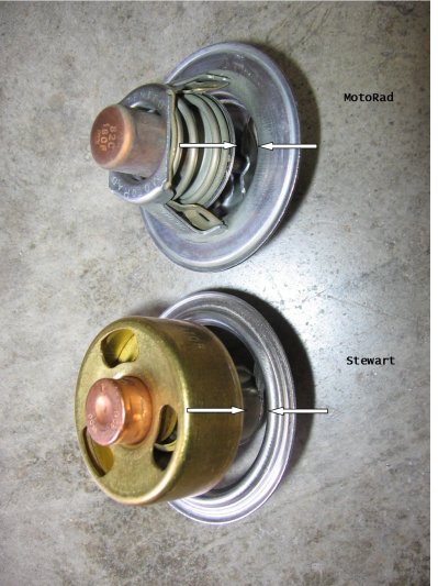
Hey Grumpy, what type of thermostat do you prefer to use. A poppet-style Robert shaw brand or similar balanced-flow design?
 
posting.php?mode=edit&f=57&p=1078

viewtopic.php?f=57&t=4701&p=19139&hilit=t+stat+drill#p19139


tstatdual2.jpg

the top styles cheaper and works fine most of the time, the lower styles more reliable in my opinion, but I drill 6 1/8" holes in the flange of either style, yes it slows the time required to get the engine up to heat up to operational temps but it also prevents wild swings in temps and maintains a far more consistent operational temp, keep in mind a t-stat has little effect on anything but the minimum temperature the engine will run at, it has almost zero effect on the upper temp range
 
grumpyvette said:
the top styles cheaper and works fine most of the time, the lower styles more reliable in my opinion, but I drill 6 1/8" holes in the flange of either style, yes it slows the time required to get the engine up to heat up to operational temps but it also prevents wild swings in temps and maintains a far more consistent operational temp, keep in mind a t-stat has little effect on anything but the minimum temperature the engine will run at, it has almost zero effect on the upper temp range

Thanks for the feedback. Kinda related question. Do you plug the water pump 'bypass' hole on the block in your builds?
 

Attachments

  • images.jpg
    images.jpg
    7.6 KB · Views: 175
bytor said:
grumpyvette said:
the top styles cheaper and works fine most of the time, the lower styles more reliable in my opinion, but I drill 6 1/8" holes in the flange of either style, yes it slows the time required to get the engine up to heat up to operational temps but it also prevents wild swings in temps and maintains a far more consistent operational temp, keep in mind a t-stat has little effect on anything but the minimum temperature the engine will run at, it has almost zero effect on the upper temp range

Thanks for the feedback. Kinda related question. Do you plug the water pump 'bypass' hole on the block in your builds?

Ive seen it done, and have a few friends that have but , Ive never bothered too as Ive yet to see any benefits
 
Starting to make some good progress now. Looks like I will be able to use my stock valve covers.
Intake question, is it a common practice to coat the intake manifold with clear coat or just run it raw?
 

Attachments

  • IMG_0441.JPG
    IMG_0441.JPG
    72.9 KB · Views: 156
Sand and polish that intake :) jk.
I never seen anyone clear coat an intake.
 
I usually bead blast then pressure wash my intakes then paint them with aluminum paint as it tends to make them look a bit better, but I doubt its critical, it does tend to make them look better and stain less from oil or coolant spills
 

I thought about polishing mine, but since it's an air gap just like yours I decided it would be too hard to get everywhere. I just left it plain for the time being, maybe later I will try polishing the intake.

BTW, your motor is really looking very nice!!!

 
Setup my distributor today and here are the measurements I ended up with.

Setup:
Distributor - Mallory Promaster Series
Distributor gasket – 0.027”
Oil pump shaft – Came with the pump Milling 10552 (5.75” long)

Measurements:
Oil pump to distributor shaft overlap = 0.29” (Measured using MSD method described here viewtopic.php?f=54&t=123)

Distributor gear lash = 0.018”

Oil pump vertical play = 0.09”

Distributor shaft end play = 0.006”

I believe all these measurements are in range except for the distributor shaft end play, seems a bit tight. I'm going to bounce it off Mallory support and see what they say.
 
Back
Top