My 1st. Street 383 Build

in most cases you install the fork and throw out bearing AFTER the bell housing installed, but before the transmissions mated to the bell housing as the trans imput shaft slides thru the throw out bearing

viewtopic.php?f=71&t=584&p=26280&hilit=bellhousing#p26280

viewtopic.php?f=71&t=6258&p=19699&hilit=pilot+bearing#p19699

viewtopic.php?f=71&t=447&p=921&hilit=fork+pivot#p921

clutch2.gif
 
Progress update, Got the bellhousing installed and dialed in using these. http://www.robbmcperformance.com/products/dowels.html
I found that I needed to move the bellhousing straight down 0.012" Very easy to do with the adjustable dowels. Here's a few pics, ignore the numbers on the tape.


Got the flywheel installed with no issues.


Installed the clutch set and ready to go.


Checking starter pinion engagement and all within spec..
 

Attachments

  • IMG_0544.JPG
    IMG_0544.JPG
    252.7 KB · Views: 172
  • IMG_0547.JPG
    IMG_0547.JPG
    230 KB · Views: 172
  • IMG_0550.JPG
    IMG_0550.JPG
    279.1 KB · Views: 172
  • IMG_0552.JPG
    IMG_0552.JPG
    260.3 KB · Views: 172
  • IMG_0553.JPG
    IMG_0553.JPG
    286.4 KB · Views: 172
  • IMG_0555.JPG
    IMG_0555.JPG
    299.1 KB · Views: 172
  • IMG_0557.JPG
    IMG_0557.JPG
    274.5 KB · Views: 172
  • IMG_0561.JPG
    IMG_0561.JPG
    232.9 KB · Views: 172
  • IMG_0564.JPG
    IMG_0564.JPG
    339.9 KB · Views: 172
Im darn impressed with the quality of the pictures and the fact that you took the effort to do it correctly.
 

That's not only very nice, but damn nice job there bytor !!!


When do you expect to install the motor in the Vette ?

 
Indycars said:
When do you expect to install the motor in the Vette ?

In the next few days I hope. I have the old motor all disconnected and ready to yank out. Just have to remove that pesky radiator first. I'm planing on having my steering box rebuilt and replace battery cables while I have easy access. So I'm thinking an initial fire up in a few weeks if all goes well.
 
Sharing a few more update pics.
Nasty clutch Z bar. Have the rebuild kit and new pivot balls on hand and ready to rebuild it.


Old engine completely disconnected and ready to pull. Hood and radiator removed for plenty of work room.


Cleaning up and detailing a few accessories along the way.
 

Attachments

  • IMG_0574.JPG
    IMG_0574.JPG
    113.1 KB · Views: 162
  • IMG_0576.JPG
    IMG_0576.JPG
    127.1 KB · Views: 162
  • IMG_0578.JPG
    IMG_0578.JPG
    145.3 KB · Views: 162
  • IMG_0579.JPG
    IMG_0579.JPG
    141 KB · Views: 162
Update, been focusing on 'the while your in there' task lately. Things like having the worn out steering gear box rebuilt, Replacing the 34 year old 'ALUMINUM' battery cables, replacing leaky headlight vacuum hoses and replacing a few seals on the ST-10 4 speed transmission.

Reverse shaft o-ring.


Speedometer gear sleeve, got a new gear, o-ring and seal on the way. That small seal was a pain to track down. The GM part number is 1240382. It had worn a groove in the plastic speedometer gear shaft as well.


Replaced the front bearing retainer seal, the old one was hard and definitely leaking. Easy job to replace.
Old seal...


Nwe seal installed...


Throughout bearing installed correctly.


Below is my first check of the clutch fork alignment. It's a bit of a challenge to measure the 5-7 deg. angle because of the curved fork lever. Finding the 0 deg. center line is hard.


I'll get some pics up later with more detail.

Just looking at it, I believe I need to move it forward some. I have an adjustable pivot and thinking I can use a hanger bent at 6 deg. as a reference. I have also read the you can just adjust the fork all the way forward till it touches the pressure plate then back it off 1/2" or so. I didn't get to spend much time on this as it was getting late. More to come.
 

Attachments

  • IMG_0621.JPG
    IMG_0621.JPG
    104.2 KB · Views: 136
  • IMG_0622.JPG
    IMG_0622.JPG
    148.2 KB · Views: 135
  • IMG_0625.JPG
    IMG_0625.JPG
    166.1 KB · Views: 135
  • IMG_0629.JPG
    IMG_0629.JPG
    167.3 KB · Views: 135
  • IMG_0633.JPG
    IMG_0633.JPG
    119.2 KB · Views: 135
  • IMG_0658.JPG
    IMG_0658.JPG
    115.3 KB · Views: 135
  • IMG_0663.JPG
    IMG_0663.JPG
    83.4 KB · Views: 136
  • IMG_0665.JPG
    IMG_0665.JPG
    72.5 KB · Views: 136
  • Clutchfork1.jpg
    Clutchfork1.jpg
    19.6 KB · Views: 135
bytor said:
Update, been focusing on 'the while your in there' task lately. Things like having the worn out steering gear box rebuilt, Replacing the 34 year old 'ALUMINUM' battery cables, replacing leaky headlight vacuum hoses and replacing a few seals on the ST-10 4 speed transmission.

Every time I try to do something like you're doing here.......one thing leads to another and pretty soon I have a BRAND NEW OLD CAR !!! ;)

I'm glad you got the patience to follow thru and take care of those things that need attention, but will be really hard to get at once the engine is installed. Hard to do when the engine is finished and just begging to be installed and driven.

 
Just a question like this, do the input shaft of your st-10 has some side play? last time i took mine out it did and i am unsure if thats normal or not.
 
mathd said:
Just a question like this, do the input shaft of your st-10 has some side play? last time i took mine out it did and i am unsure if thats normal or not.


I'll double check but I didn't notice much if any side play.
 
mathd said:
Just a question like this, do the input shaft of your st-10 has some side play? last time i took mine out it did and i am unsure if thats normal or not.

they all have SOME minor side play, as in you can move the splined shaft in relation to the trans, THROW OUT BEARING collar (#1 and #2) but its MINIMAL, obviously if its easily wiggled theres something wrong

m22fine1s.jpg
 
well its the splined shaft that move, didnt measure but probably about 1/32"
it has some resistance (no metal to metal banging)and trans work flawlessly.
 
I ended up obsessing about the clutch fork angle so I contacted Ram tech support for their assistance. With the curvature of the clutch fork it was hard for me to tell what I was looking at having never done it before.

Here's the details on my setup and the questions to RAM tech support:

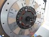
Clutch - RAM Powergrip 98764
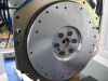
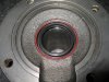
Flywheel - RAM 1501
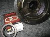
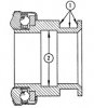
Release bearing - Came with the clutch set, measures 1.25" so I believe it's a #488
Bellhousing - Lakewood 15000
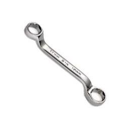
Clutch fork - GM 3887177 stock 1978 Corvette
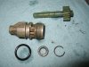
Fork Pivot Ball - 1.5" non-adjustable that came with the bellhousing (and) a 1.66" adjustable Lakewood

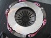
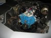
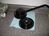
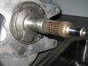
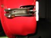
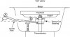
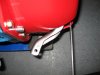
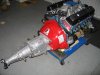
I installed everything and used the non-adjustable pivot first to see how things looked. I felt the clutch fork was too far back and looked almost parallel to the back of the bellhousing.

1.5" pivot installed top view

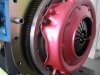
1.5" pivot installed side view


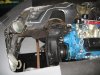
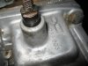
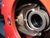
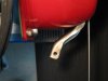
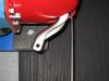
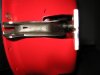
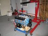
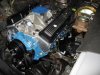
I then replaced the non-adjustable pivot with the adjustable Lakewood unit and adjusted until I had about 1/2 inch of clearance between the clutch fork and bellhousing. The adjustable pivot height ended up at 1.66". Now the fork is pointing forward slightly. I have read that you want a 5-7 degree forward angle on the fork but it's hard to judge the angle with the curved clutch fork.

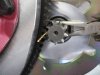
1.66" pivot installed top view

1.66" pivot installed side view


The RAM support folks said the angle I get with the 1.66" pivot is what I'm after so good news. Now I can obsess about something else. :D
 

Attachments

  • 1.5 pivot_top.JPG
    1.5 pivot_top.JPG
    103.1 KB · Views: 250
  • 1.5 pivot_side.JPG
    1.5 pivot_side.JPG
    72.6 KB · Views: 249
  • 1.66 pivot_top.JPG
    1.66 pivot_top.JPG
    106.6 KB · Views: 250
  • 1.66 pivot_side.JPG
    1.66 pivot_side.JPG
    76.5 KB · Views: 248

Your posts are always informative with plenty of excellent pictures and links.

Good to hear you can move on now with your life for a few days until you can find something else to worry about. :D

 
Hey Grumpy, have a few questions for you as I'm getting things buttoned up..

I'm about to install the transmission on the new build up and I have a question about the clutch linkage. I have used some moly paste (sparingly) on the pivot ball and the #1 area in the picture below.


Here http://www.novak-adapt.com/knowledge/clutches_etc.htm they recommend also packing the #2 area with grease. Is this the correct way to do it? Also, I have read conflicting info about lubrication a bronze pilot bearing. The two opinions are to apply a very light coat of moly on the input shaft tip or, don't lubricate because the bronze pilot bearing is 'self-lubricating' and too much moly added could cause it not to lubricate properly.

One more question on header fasteners. I like the idea of using studs instead of bolts.
http://forum.grumpysperformance.com/viewtopic.php?f=56&t=1045&p=5148&hilit=header+stud#p5148

Do you use any kind of lock washer behind the nut and what would you torque the nut to when installing?

Thanks in advance....
 

Attachments

  • throwout_bearing_lubrication_points.jpg
    throwout_bearing_lubrication_points.jpg
    11.7 KB · Views: 187
bytor said:
Hey Grumpy, have a few questions for you as I'm getting things buttoned up..

I'm about to install the transmission on the new build up and I have a question about the clutch linkage. I have used some moly paste (sparingly) on the pivot ball and the #1 area in the picture below.


Here http://www.novak-adapt.com/knowledge/clutches_etc.htm they recommend also packing the #2 area with grease. Is this the correct way to do it? Also, I have read conflicting info about lubrication a bronze pilot bearing. The two opinions are to apply a very light coat of moly on the input shaft tip or, don't lubricate because the bronze pilot bearing is 'self-lubricating' and too much moly added could cause it not to lubricate properly.

Ive always used a thumb full of MOLY past grease spread on the pilot bearing and on the area #2 in your diagram, but Ive never put any on area #1 and I cant remember ever having any problems

One more question on header fasteners. I like the idea of using studs instead of bolts.
http://forum.grumpysperformance.com/viewtopic.php?f=56&t=1045&p=5148&hilit=header+stud#p5148

Do you use any kind of lock washer behind the nut and what would you torque the nut to when installing?

Thanks in advance....

Ive always found the STAR LOCK WASHERS, under the nuts , and used with the studs was all thats required, I generally don,t get overly concerned with exact torque loads I just tighten them about as tight as I can get the nuts with a short box end wrench and have not had any problems

shortboxenda.jpg


STAR-LOCK-WASHER.jpg
 
Got the new engine installed with no major challenges or issues.


One snag I discovered after the engine was installed is one of the trany mount bolt holes was stripped. Wish I had noticed it before. But fortunately, it looks like I have enough access to do a Helicoil repair. I'm thinking I'll go with studs instead of bolts this time as the trany case is aluminum.

If I had not done the research and had the knowledge here on this forum behind me, I'm certain I would have screwed something up or hurt myself. Aside from the technical stuff here, the safety tips are invaluable. More to come....
 

Attachments

  • IMG_0683.JPG
    IMG_0683.JPG
    134.3 KB · Views: 153
  • IMG_0692.JPG
    IMG_0692.JPG
    142.7 KB · Views: 153
  • IMG_0695.JPG
    IMG_0695.JPG
    150.8 KB · Views: 153
Back
Top