My Cam Research for the Experts Eye

from what I can see your fine!
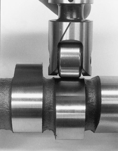
the cam, lobe is not designed to run centered on the lifter bore, specially, if its a flat tappet cam,
and the rollers on a roller lifter are running on the lobe as its
designed to do on a slightly off center lobe location.
lobe8large.jpg
 
Thank you !
Upon more research I was finding out similar info. Here's a pic representing about where the roller lifter rides on the lobe.
You can hopefully see the flat track made in the assembly lube, there's still about .125 in of untouched lobe to the right of where the roller lifter made contact.
So as you say, this all looks to be ok. I'll also stick the distributor in only to also verify gear engagement with the cam is good.

214202215531.jpg

Check, check, and check again....
 
Last edited:
I spent half a day fiddling with the oil pump today. I'm re-using the Melling HV pump that's set up for the Milodon 7qt pan. Nothing wrong with it. I'm also re-using the steel sleeved distributor drive rod and the rear baffle.
First thing I found out was that the ARP stud/ hex nut interferes with the pump housing. Now I understand why the kit includes a smaller 12pt nut.

I loosened both nuts on the rear main so I didn't run the risk of warping the cap or something, swapped the one nut, then torqued both in steps back to 110 ftlbs.
20220315_144406_HDR_resized.jpg

I still needed to slightly grind the pump though.
20220315_144442_HDR_resized.jpg

I then had to add holes in the baffle for the studs. I also checked depth of stud into the cap and there's plenty of clearance to the bearing shell.
20220315_144650_HDR_resized.jpg

I'll add a very very thin smear of Permatex #2 to ensure sealing at pump to baffle to cap then tighten nut to spec.
20220315_145313_HDR_resized.jpg

Another learning curve today.
 
Last edited:
thank you for posting the pictures and verifying the pump mount stud does not have clearance/ depth contact issues with the crank bearing shell in the rear main cap
 
thank you for posting the pictures and verifying the pump mount stud does not have clearance/ depth contact issues with the crank bearing shell in the rear main cap
I wanted to be really careful about that - I followed your posted info. If you look really closely at the base of the pump stud you may see a thin white line. That represents bottoming out.
The stud couldn't thread in that far but I wanted to be really sure I knew how much clearance I had. Before tightening the nut I put a spot of white paint on the top of the stud so I could see if the stud turned further as the nut was torqued. It stayed in place.

20220315_144650_HDR_resized.jpg
 
Info:
Heads are still at the shop, short block is essentially together, so I've been working on electrical till the heads are done. I still need to degree the cam though.
I'll be using the Felpro composition/permatorque head gaskets, not the MLS versions since the block surface is clean and flat but was not machined. The comp gaskets per Felpro are more forgiving plus an added benefit is they are half the cost of the MLS versions.
 
I'll post info on my heads when I get them back. They're actually 427 heads (large oval port) that have worked well, I had done some mild porting and polishing before I first installed them.
I've also decided against powder coating oil pan and timing cover, not cost effective, and I'm not building a show car. Both are very sturdy pieces and there's no need to replace either. I'll blast them very lightly, sand, apply metal etch primer and ceramic engine paint in a gunmetal finish.
20220325_104209_HDR_resized.jpg
 
Last edited:
Hooray - one month later my heads are done. I've had other things to do so it didn't hold me up, but I'm glad to get them. They look good, several valves were replaced, all seats done, seals etc and new springs installed.
352022163227.jpg

Still more wait time ahead though - we're making one last rv trip before the summer madness starts. We don't travel May-October so hopefully I'll have the engine together and back in the car soon.
 
Last edited:
Question please.....
This is about one of the coolant passages vs head gasket.

Here's the gen 4 block with the 3 lower coolant passages. The one I'm asking about is right under the blue tape.
20220407_135207_HDR_resized.jpg

Here's one of the heads (427 heads that have been on the engine since day 1). The 3 coolant passages are in line as I've seen on every BBC head.
20220407_140120_HDR_resized.jpg

This was the old head gasket - note that the hole for that particular coolant passage is only partially aligned. The cylinder head aligns with the head gasket.
20220407_135649_HDR_resized.jpg

I never had an issue with sealing but this engine was always fiddly to keep cool, even with a good crossflow aluminum radiator and dual spal fans. Didn't really overheat but wanted to stay at 200-210.
Do you think this partial alignment had any impact? I'm not sure if it did but wanted to ask about it.

And do you think I should open up that block cooling passage to align with the head gasket and the cylinder head passage? I'm a bit hesitant because of isolating the metal debris and/or that I might screw up the block.
 
Last edited:
,most guys I know either have that coolant hole threaded, pluged, and decked,
and redrill the plug to match the head gasket they want to use
OR
use the solid copper head gaskets
untill recently they made the exact head gasket you need but from the info Ive seen while looking they are no longer made.
the use of solid copper head gaskets sprayed with copper coat avoid ANY LEAK ISSUES\


https://www.jegs.com/i/SCE+Gaskets/...6ISFsKSp1jzyMUa62MvenZczmNVhqcaIaAla2EALw_wcB


Last edited:
Thanks very much, lots to go over. While we're on the road I'll go thru the info and make a determination for going forward. This helps a lot.
 
Back home and back on the engine, need to get this thing done.
I started to degree the cam but ran into a fiddly problem with being able to turn the degree wheel without loosening the balancer bolt after figuring TDC with my dial gauge. Not a big deal, but I paused on this till I get a 1/2-20 stud to use so I can turn the degree wheel without loosening the stud in the crank. I know you can buy specific sockets for this, but this simple/cheap setup will work fine.

Anyway, I did go ahead and determine head gasket selection and verify with Fel Pro tech line. They were very helpful.

Backstory - this engine always ran hot no matter what I did - hi flow pump, big crossflow radiator, dual Spal w shroud. The block as you've seen has the larger 2 coolant passages at the rear, plus the 3 center coolant holes - it's a parallel flow block. Heads match up fine. I had used a 1017 gasket that's essentially a hybrid of parallel and series cooling blocks. The issue that was happening was that coolant flow tended to go thru the 2 larger rear passages (square & triangular looking holes) and in general flowed too quickly thru the engine, thus inefficient heat transfer. This makes sense to me as the hot running was a steady rise to 210/220 usually and it would just not come down from that. Summer temps over 90 in any sort of traffic, forget it.
Talking with Fel Pro tech, the recommendation was to use 1037 gasket that has the 3 center coolant holes but only uses the square hole in the rear of the block - it blocks off the triangular hole. This helps to limit that rear coolant flow and increases flow thru the center holes, should be less short-circuiting and more time in the engine for better heat transfer. I also landed on the 1037 after days of researching but of course I wanted to verify with the mfg.

So the final selection is the Fel Pro 1037, which is .039 in compressed thickness and 4.370 bore. I checked all cylinder deck heights and arrived at an average of (-).020 in (piston in the bore) and bore size is 4.28 in. The previous 1017 had a spec of .0385 in and 4.52.
 
The issue that was happening was that coolant flow tended to go thru the 2 larger rear passages (square & triangular looking holes) and in general flowed too quickly thru the engine, thus inefficient heat transfer.
It also had less heat to give up in the radiator. I think your perspective is wrong on this. What is happening with the new head gasket is a balancing of flow for all cylinders, thus it will cool the engine as a whole better. It certainly will allow more ignition timing since the middle cylinders be cooler and closer in temp to the outer cylinders thus less prone to detonation now.

If coolant going thru the engine too fast was a problem, then why would there be high flow pumps???

Where is your sensor for temperature ?
 
Rick those are good points. I agree with the overall coolant balance being better. I remember as the engine ran at that higher temp slight detonation would happen. I had spent a lot of time setting up an ignition curve so I knew that the timing was good.
I know that a higher flow pump can support a higher block pressure and reduce steam pockets but in my case I think I kept trying to fix unbalanced coolant flow. FP tech was pretty adamant that the issue was the short circuit of flow with the 1017 gasket. Hopefully the 1037 will be a problem solver.
Water temp is taken at right front of intake, fan thermo is on left front of intake.
 
Exercise in frustration yesterday and today trying to degree the cam. Just not getting consistent results.
Yesterday the degree wheel wanted to loosen when I rotated the engine CCW, so I made a double nut assembly to hold everything steady. And I used some old flex plate bolts to help me lever the engine backwards so I didn't risk loosening the degree wheel. That all worked fine.
I did verify TDC but I'm just not getting constant repeatable results on intake and exhaust opening and closing degrees. I'm using the .050 specs given with the cam and my understanding is that if you come up within a degree or 2 of the specs you should be ok. I've looked at a ton of videos to ensure I'm doing it all correctly.
Lobe lift looks ok but I get intake and exhaust opening about 5 degrees off of spec, closing for each is within 1-2 degrees of spec. And I'm having trouble getting to lobe centers as well. I'm all goofed up so I walked away for today.
I ordered some extensions for my dial indicator to ensure that the plunger end can fit right into the center of the lifter. I'm using the top edge of the lifter and its possible that the rounded end of the indicator stem may be wobbling a bit. I know you can get an indicator that fits into the bore but I didn't want to buy what may be a one time use tool. That may change if my frustration increases.
There's always the possibility that the cam isn't ground correctly but I want to be 1000% sure that my measurements are correct first.


Last edited:


Thanks Grumpy, I'll go over every bit of this.
 
Last edited by a moderator:
I ordered some extensions for my dial indicator to ensure that the plunger end can fit right into the center of the lifter. I'm using the top edge of the lifter and its possible that the rounded end of the indicator stem may be wobbling a bit.
If you are using a hydraulic lifter this may cause the lifter piston to depress causing your readings to be invalid. I can't be sure what you mean by "top edge of the lifter" without a pic. Below is how I did my setup, is this what you mean?

IndicatorAndLifter1496.jpg
DialIndicatorSquare02_1503.jpg
 
Hi Rick, yes exactly. I ordered the indicator extensions to duplicate the setup you had.
I think the lifter has enough resistance to push up on the dial indicator without moving the lifter plunger. I'll use the extension centered in the lifter but I'll also place a flat solid circular washer across the top of the lifter and repeat the measurements to see if there's any difference.
I also bought a crank turning nut (has a keyway built into it) so I can turn the crank in either direction without needing a bolt. I will use a bolt for the degree wheel but that's just a slight tightening needed.
While I wait for that stuff I masked and primered the heads and started prepping the oil pan for prime and paint.
In the background I've also continued to work on the car itself.
 
Any chance you are going to take a lift reading every 2°, then we could really compare camshafts ! Nah, that's one hell of a lot of work ..... 180 times, then you record the number, turn it two more degrees ...... or 360 or both intake and exhaust.
 
Back
Top