One of a Kind TRI Y header for 134L Willys

Mark W.

Member
OK I have been building a Tri Y design header for my 48 Willys CJ-2A "restomod" project.

I am running a Willys 134L engine

specs are as follows

Engine bored .060" over now making 140 cu in. Bore 3.185" Stroke 4.375 1-3-4-2
Compression ratio has been raised to 7.2-1
Stock BHP 60 at 4000rpm stock torque 105 ft lbs at 2000rpm
Stock valves and cam spec's as follows:

Intake
Opens 9° BTC
Closes 50° ABC
Duration 239°
Exhaust
Opens 47° BBC
Closes 12° ATC
Duration 239°
Valve Opening Overlap 21°
Valve lift both intake and Exhaust .351"

The intake manifold is a Modified Pierce cast aluminum that was originally made for a 1500cc MG engine I split the Plenum and added a .410" spacer that spread the runners out to match the engine. I then came back and added an aluminum plate with Carb Bore sized holes to the top to return the Carb mounting holes to thier proper spacing. I then added a .5" Micarta (Phenolic) spacer on top of that. The Carb will be a Weber DGV 32/36

The engine has been computer spin balanced from the crank pulley through the clutch pressure plate.

Ignition will be an Autolite IAT-4405 Vacuum advance distributor with a Petronix Ignitor I trigger and a MSD-6A spark box Accel Super coil and Wires (resistor type) and Champion UJ-8 Plugs.

Fan and fuel pump delete

Projected weight for the Jeep is 2600 lbs

Final drive gearing is 5.38's with a 30% Overdrive 29-29.5" tall tires.

Typical operating rpm range 1000-3000 rpm with a 4000 rpm red line.

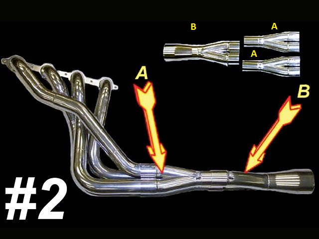
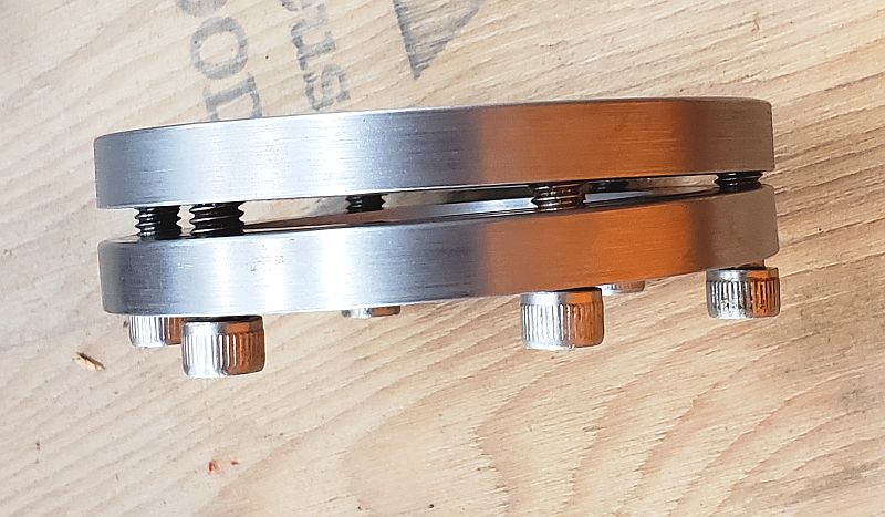
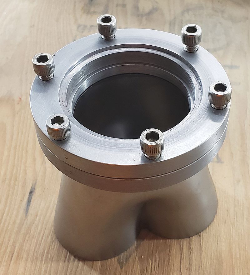
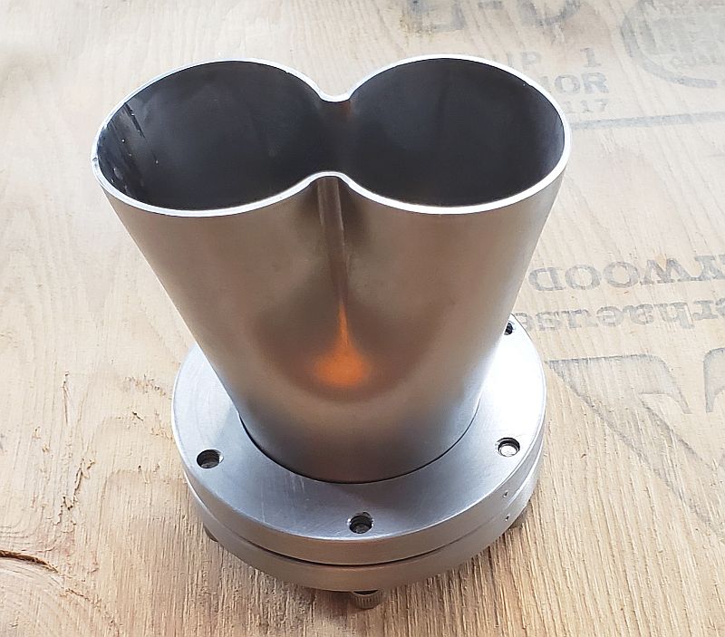
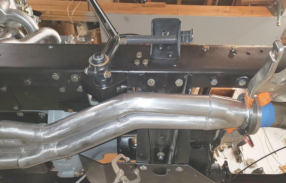
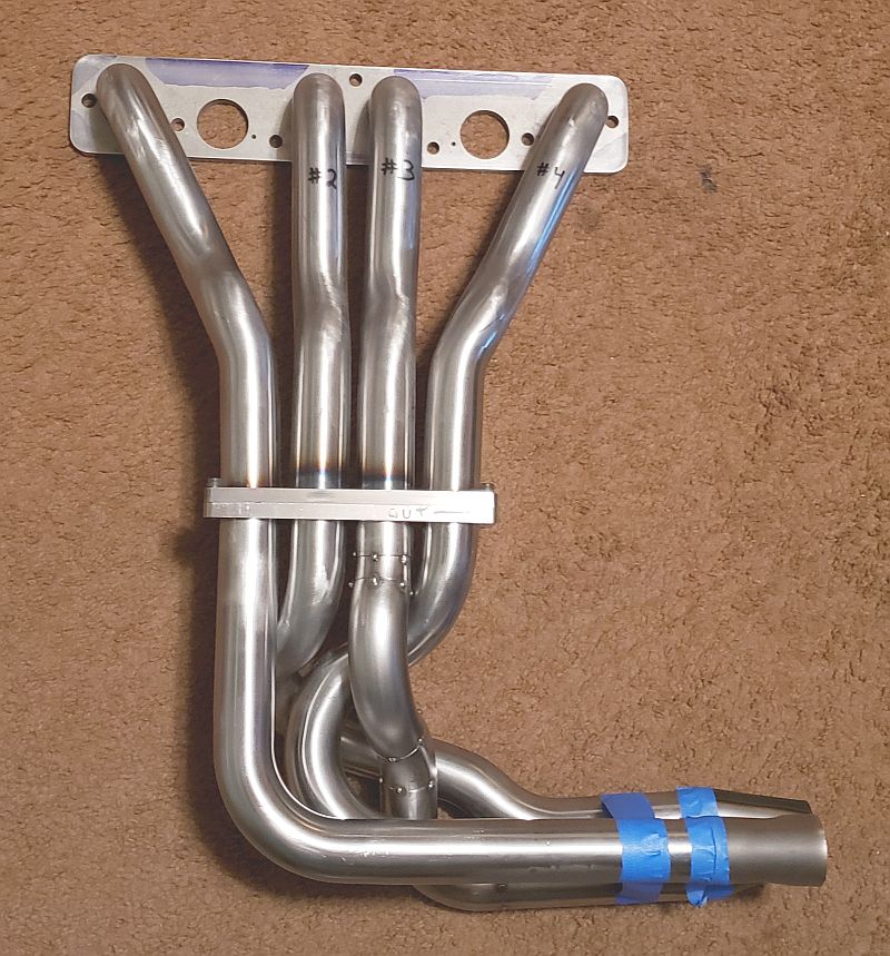
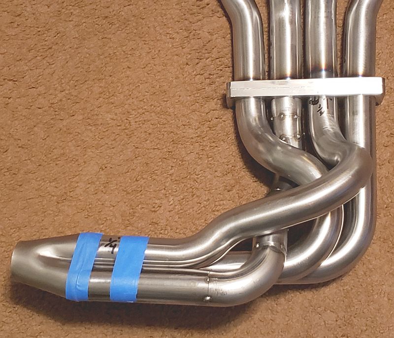
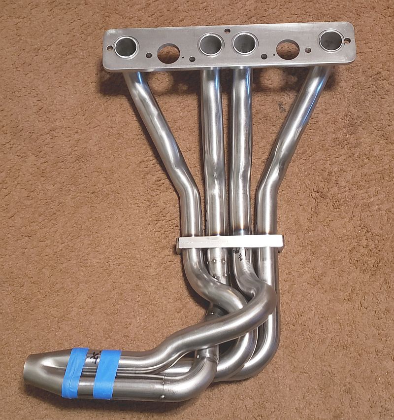
I currently have the Primary section of the Header built. It is 1.375 ID tubing (same as the exhaust ports) with an average length of 36" valve to 2 into 1 collector. Looks like this:


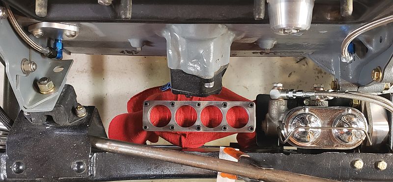
And a photo of the Intake manifold


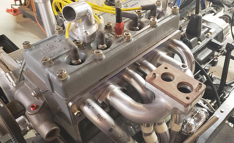
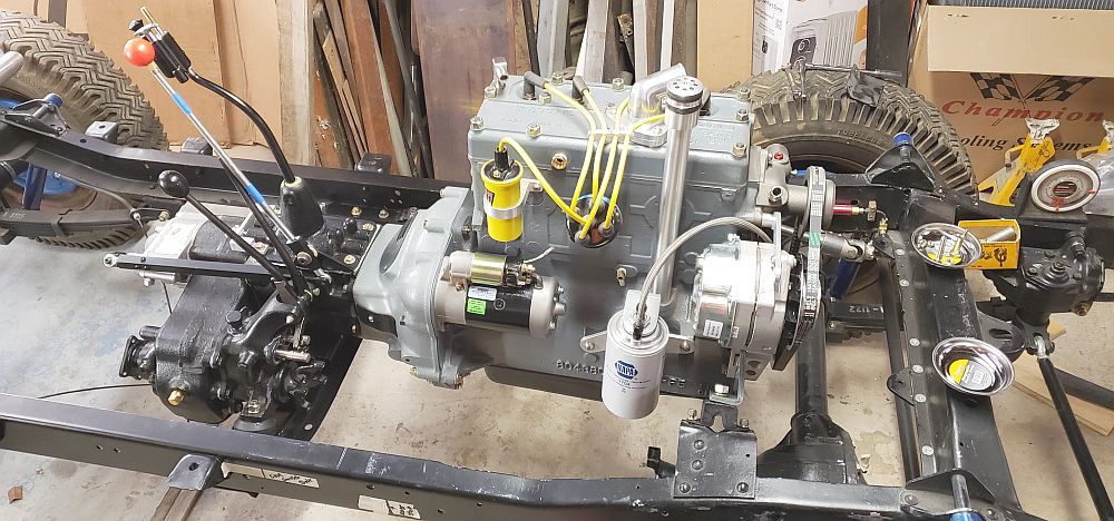
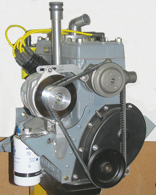
and a couple shots of the rest of the engine:


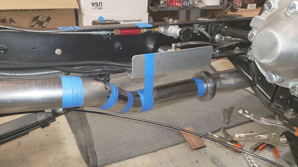
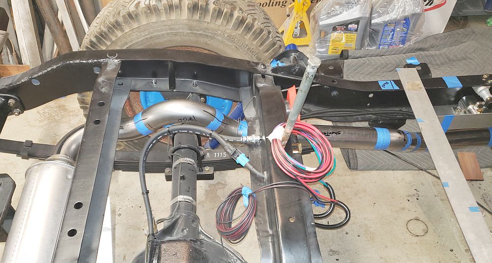
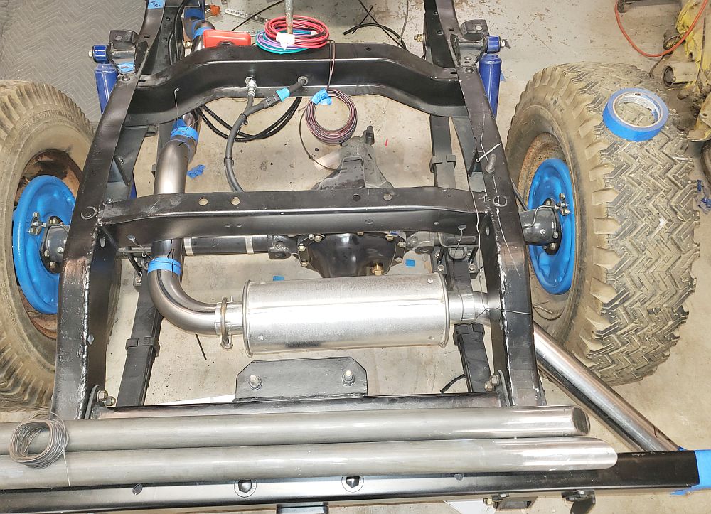
I need help trying to decide what would be the best length for the 1.75" OD Secondary's. I have room for anything up to 36" long on the other end at least 18" long would fit best with 20-24" being near ideal (this is to get pas the transmission cross member and to convert to the 2.25" OD tail pipe before having to go up over the rear axle.

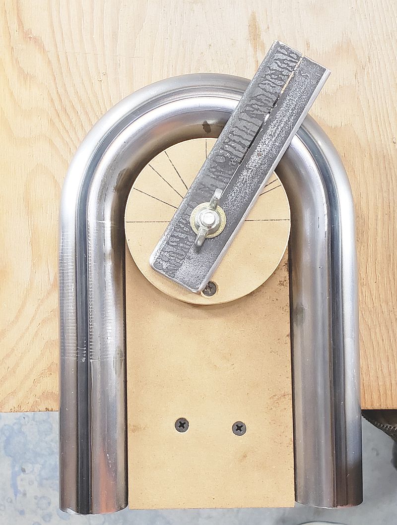
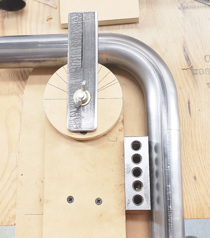
As you can see this has been quite the project all done old school the only thing a computer was used for was research and ordering bends. everything is MIG welded and ground smooth. I will be having Finish Line Coatings here in Miliwaukie OR doing the Ceramic coating on them.

SO anyone have a guess as to what my Secondarys should be or should I just make what fits best.

And PLEASE don't waste time telling me I am crazy for doing all this work to a Willys 134L jeep engine. That horse has been beat to death so many times over the 10 years of this build it would just be a waste of time.

To those that will help THANK YOU SO MUCH.

Mark W.
 
WOW! thats impressive work,
thanks for the clear pictures, obviously clearances must be considered, but 15"-18" is what Id shoot for in length for stage 2|
flowre2.jpg

having built more than my share of custom headers over the decades,
I know how time intensive it can be and your results look to be far higher quality,
than most custom fabricated headers I've seen built,
and the clearance on the spark plugs and wires,
obviously is not an issue like it is on most V8 applications ... with a flat head 4 cylinder.
(a factor some guys forget to check carefully) during custom header fabrication
care to comment on the fabrication, custom fitting, cutting, and welding process?
where did you order the header component s like exhaust plate collector tubing,?
what welder, TIG rods, or mig wire, shield gas, amp settings etc.
flo-c158218234.jpg


http://garage.grumpysperformance.com/index.php?threads/building-custom-headers.961/page-2

http://garage.grumpysperformance.co...e-sizing-for-peak-torque-rpm.6461/#post-20459

http://garage.grumpysperformance.com/index.php?threads/header-dimension-calculator.15013/#post-84911


http://garage.grumpysperformance.com/index.php?threads/x-or-h-pipe.1503/
 
Last edited:
The design is a lot of thinking time. I drive a Dump truck for a paving co so I have a lot of time to just think on things. Then I got to work with pencil and paper working up rough ideas. The next step once I had the engine and drive train in the chassis was to assemble as much of the stuff that would end up in the way as possible. This was when I found out my basic design which would have had the primary's traveling past the Oil Pump (dead center in the block right in the way) in a group of 4 cubed would not in any way work. Ao I changed the idea or design direction to the 4 inline setup you see. Since the 134L has mechanical tappets they need to be adjusted at least every couple years so splitting the Primary's where I did made that easier at the same time made it so assembling the exhaust on a finished vehicle could work.

I then scoured the on line catalogs for what bends were available in the size tubing I needed and then I made some wood models. I settled on a 2.5" CLR for the primary tubes based on the distance from the Intake manifold. I then worked out the easiest way to get out past the oil pump while staying as far from the left frame rail as possible. I needed room for my Steering shaft to pass through there. For straight sections of pipe I used 1.5" OD under sink plastic pipe from the hardware store. And about a roll of masking tape to hold things together as I used what I had like a Lego set and tried to make something that would work.

The bends came from JDM performance in CA The welder is a Lincoln Weld Pak 140 I bought when it was obvious the only way I would get things on the Jeep welded the way I wanted was if I learned to do it myself. The wire is .024" from the local weld shop. 25/75 gas

I made a small tubing cutting jig I used with my 4x6 horizontal/vertical bandsaw and the cuts were trued up on my 2 X 72" belt grinder (I used to be a Custom Knifemaker) the jig looks like this:

The awesome little 2 into 1 collectors came from Cone Engineering also in CA the simple design and short length was what sold me on them.


Nothing fancy but it worked well.

The Header Flange was made based on measurements and drawings off a very good fitting Fel Pro exhaust gasket. I used 3/8" thick 1018 cold finish steel then once I had the blue prints I then transferred them to a piece of Micarta and drilled 1/4" pilot holes then using this "Drill Jig" I made a prototype from 1/2" thick MDF and did some trial fitting. Once I had the corrections I then went back to the Micarta and since I can epoxy a plug into any hole in the Micrata I got the Drill jig pretty dang accurate. Once that was done. I used it to drill a Flange Blank with 1/4" D holes. This then becomes my actual Drill jig. I used it to drill pilot holes in the actual flange. Then placed that in my Mill Drill Vise and using a center finder located the first hole. Then it was just a matter of Drilling out to 1" D then switching to my APT large hole drilling fixture (it uses a 1" pilot with a 1/4" thick spade type bit insert. I first drilled the 1.75" Relief for the welding of the tubes. Then drilled the hole out to 1.5" D to fit the tubing.

The 3 in line flange was made in a similar fashion but the two pieces were made at the same time to keep perfect alignment.

I also made a circular flange that will join the end of the Secondary's to the Tail pipe. This I made on my little 9 x 20 lathe as it was to large to fit into the vise on the Mill Drill


.


Once the tubes were goober welded together I then took to my belt grinders and cleaned up the welds followed by a flap sander and finally see sawing strips of sand paper to get then pieces to 180-220 grit finish

https://www.photo.net/gallery/464820#//Sort-Newest/All-Categories/All-Time/Page-1


https://www.photo.net/gallery/464820#//Sort-Newest/All-Categories/All-Time/Page-1

My big things to look out for were the Oil pump dead center in the engine and sticking a good 3" out the side. The need for clearance from the Steering shaft that passes through the left engine mount and will connect to the column some where near Tube #4. And then the Master Cylinder which is frame mounted and directly in the path of any tubes. SO they had to go under it.


And then just behind the MC is the clutch and barke pedal linkage and just beyond that is the Transmission Cross member. The tubes have to move out towards the frame rail to be able to get as high as possible passing it. Keep in mind this is a JEEP so ground clearance is a BIG concern. Most hot rods don't have to deal with 12" D rocks or ditches or mud ruts but a Jeep does.

Hope this answered most the questions. the other day on one of the Willys Jeep Face book pages someone asked me if I had a dxf. file I could save on the header I had to look it up and then laugh. No computer design file here this is all shade tree mechanic stuff.

Choosing to Resto mod a 1948 Willys CJ-2A Jeep is not like what street rod guys or classic rod guys do. I have no catalog of neat parts to bolt together. I have to make almost everything for everything. When you look at my engine everything that is aluminum is hand made except the neck on the thermostat housing. Which I took one designed for a SBC and then made the mounting plates for. The Oil fill and breather tube is acutally made from some Aluminum tubing with parts from a pre war Leica Camera Close up tube set.

I currently have parts from 27 different jeeps dating from 1946 to 1972 in the mix I have reproduction sht metal from 3 different co's and about 50% of the Tub (you guys call them bodies) is made from scratch I have had to modify almost 50% of the Bolts used to assemble this. I even have adapted a Toyota FJ-40 Starter to the engine.

Every single system on the Jeep has been upgraded

Saginaw Steering with Borgenson joints and Ididit classic column
The 11" drim brakes are from a 68 Wagoneer with a 72 CJ-5 MC
The electrical system is 12V 105amp Delco Marine Alternator I even had to reshape the Right inner fender to allow a huge battery tray for the Series 31 battery all made from scratch fuse and relay setup
The engine work you know about the Clutch was upgraded to an optional 9.25" clutch only available a few years in the 60's this required a different flywheel and bell housing and linkage. The Transmission has all new gears and shafts the Transfer case was up graded to the latest two stick version of the D-18 Then a 30% ATV brand Overdrive was installed between the tranny and transfer case giving me 12 forward gears and 4 in reverse.

the rear axle was up graded to the strongest rear axle ever put under a CJ the Dana 44 30 spline flanged it now has an Eaton E Locker and 5.38 G2 Gears with SKF bearings and seals.

I made all the suspension parts except the U bolts and the Springs.

You get the idea. LOL Its a Street Rod or Resto Mod or custom or FrankenJeep It even has its very own theme song Roger Millers CHUG A LUG its been called that since the song came on the air in 1965.
 
Damn fine job Mark and what determination to finish that beast. It will be a tuff one.
 
The Header was the last big construction project. I still have to rebuild the Distributor and figure out how to install the Petronix unit (no kit for my dizzy) The cam fits its really just figuring out where to place the pikup. Then I have to go through the drive shafts. I have done so much in chunks and segments really I am down to assembly. The sht metal is painted (still have to wet sand and buff) Heck I even have the heater all plumbed and ready to go in.
I'm hoping to be off work another 6 weeks cause once we start up (I work for a Paving co.) I'll be 6 days a week until Nov again. I really want this on the road late this summer.
 
Interesting.
Its a High Output 4 cylinder Flathead engine 1948 the Willy's.
Ford Flathead V8 had 100 horsepower later years.

Its strange but the Farmers had more advanced engines in their tractors in the same era.
Allis Chamlers WC & WD 1939-1953 all had Overhead valves with solid lifter camshaft.
Own a 1952 Allis Chamlers WD.

The crankshaft stroke at 4-3/8" in the 1948 Willy's will make it strong.
Tractor engine stroke length.
Not much cam overlap. They say you need at least 55 degrees overlap to make use of the 5th overlap cycle.
But the Tri-Y header may likely trick the engine & make more torque.
 
That's some impressive fab work using your creative mind!!!

Thanks for the great photos!!!
 
No the 2 wheel Belt grinder aside from the backstand Idler assembly is my own making. I also made other style machines some I sold. Those looked like the ones in this gallery

https://www.photo.net/gallery/464820#//Sort-Newest/All-Categories/All-Time/Page-1

The larger three wheel machine I made a number of an sold to other knifemakers but at the time it was either make knives or machines and I was doing pretty well making knives.

The design is all my own. This was done back in 86-87 now days there are more advanced factory machines some of which use the same ideas I came up with.'

The lathe is a Central machine 9 x 20 nothing special I still don't know how to thread with it. One of these days
The Mill Drill is an older Jet JMD-20 the largest one they made no longer avalable I think and 18 is the biggest now. Its about worn out. I need to source or make a new lead nut for the table.

The saw is 4x6 the same design as a Grizzly like this one but now over 30 years old https://www.grizzly.com/products/Grizzly-4-x-6-Metal-Cutting-Bandsaw/G0622
 
OK Exhaust system now goes from the Block to the exit under the rear cross member behind the Right rear Tire.

I will do the welding on the tail pipe section tomorrow. Then once thats done I can come up with some hangers

A shot of the Secondary's Not as pretty as the Primary's since they are hidden and my lunatic OCD gave up when my back did. Not to mention my supply of abrasives.


And the Tail pipe in all its taped together glory. Coming off the Flange on the back of the Secondary's and heading past the Brake stuff. Also angling in towards the center of the chassis.


Up over the axle. I would have liked it to be a good 1/2" higher as the bottom of the pipe is the same level and the contact surface on the rear axle bumpers. I might try to raise it a little once its together with the hangers.


And a rear view showing my huge Muffler (a flow through Turbo style) And the exit pipe.

 
love the detailed pictures you posted, very helpful in defining what you've accomplished,
impressive work!
 
Thanks guys after this a few days of tying up the loose ends on the Exhaust build then I think I will attack the Carb and Throttle linkage (I have to make a 90 degree turn in roughly 3" of space so I think I am going to come up with some sort of cable like the use on Motor Cycle brakes in a steel tube. Complicated by the Hand throttle that also has to do the same thing. And be very very smooth in operation.
 
Toyota's had/have throttle cables in a steel tube and some were at 90*. Get the whole setup with pedal assembly and be done with it. I use what ever I've seen on anything that might work.


Or you can buy a drive by wire setup.
 
Yea I already have a custom pedal I made as well as the pivot mounted to the back of the engine all I need is to get from the arm to the carb. And a simple 90° bend in some cable will do it.
 
Back
Top