If your installing new O2 sensors for your EFI system the rather obvious first requirement is to make sure they are matched to the control unit thats reading the data, and that the mount location limits their potential to be damages and allows easy access for maintenance, you also want to use some anti-seize on the threads so they won,t tend to rust solidly into the mount bungs your welding into the collectors
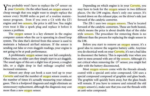
placing them in the primary tube of a header limits the sample to the related cylinder, placing it in the collector samples the average of that cylinder head, if you were to place it in the (H) or (X) pipe you would get the average for the whole engine and loose a good deal of your diagnostic info as to the location or cause of a fuel/air variation, now the heated wide band style seems to work fine in the header collectors and Id place the sensor in the most easily accessible location you could, about mid collector, the narrow band single wire style should be placed in the collector as close to the primary pipes as practicable, but remember the narrow band tend to read accurately only near a fuel air ratio of 14.7:1 while the wide band heated O2 sensors are more accurate over a wider range of fuel/air ratios and keep in mind you want the wires routed so road trash won,t bust/snag the wires and the wires won,t burn on the hot exhaust pipes.
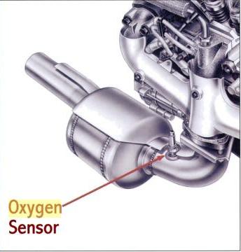
bungs can be welded to header collectors, in several locations
http://www.jegs.com/i/JEGS/555/30742/10002/-1
http://www.jegs.com/i/JEGS/555/30747/10002/-1
http://www.jegs.com/i/Edelbrock/350/3591/10002/-1
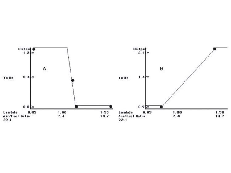
it helps if you understand that oxygen sensors do not measure your true fuel air ratio,entering the engine, but instead measure the remaining oxygen content of the burnt exhaust gases,and there are both narrow and wide band sensors
INFO OFF THE NET
"
The O2 sensor generates voltage in the range of about 0 to 1 volts. Higher voltages (greater than 0.5 volts) means there little or no O2 in the exhaust and indicates a rich mixture. Lower voltages (less than 0.5 volts) means there is a lot of O2 in the exhaust and indicates a lean mixture.
Check the number of "O2 cross counts" with a scan tool. This is the number of times the O2 sensor voltage crosses 450 mV in a sample period (which I believe is 10 seconds). The higher this number is the better. I think a good minimum is 10 but hopefully you'll see values above 20.
Although they don't last forever, O2 sensors are frequently replaced when still good. But if yours has white deposits on it,or its wet black and oil coated it's probably contaminated.
If you remove your O2 sensor and decide to reinstall it, make sure to use some of the special high heat anti-seize (which is made out of tiny glass beads). New sensors come with it pre-applied. (But if you install and remove a new sensor, you need to apply more anti-seize!) The stuff I use is AC/Delco High Temp Anti-Seize Compound (part 5613695).
O2 sensors are another part your local AC/Delco distributor has cheaper than the dealer"
http://www.carcraft.com/techarticles/cc ... to_04.html
http://www.carcraft.com/techarticles/cc ... index.html
http://www.diyautotune.com/
viewtopic.php?f=44&t=469&p=6061&hilit=scan#p6061
You cannot turn OFF the rear 02s, only turn off their error codes from tripping.
Bad idea not using the rears as they also are used by the PCM to compute the fuel trims
racingvette posted this additional info
"As per GM :
The rear oxygen sensor, located after the catalyst, is used for fuel trim corrections on OBD-II vehicles. By virtue of its location, the rear sensor is generally protected from high temperatures and much of the contamination that affects the front oxygen sensors.
In addition, the rear sensor sees exhaust gases that are equilibrated – they have already been converted by the catalyst so that there is very little residual oxygen.
This allows the rear sensor to respond to much smaller changes in exhaust gas oxygen content. In turn, it then possible for the rear sensor voltage to remain near the 0.45 volt switchpoint.
This characteristic allows the rear sensor to be used for fuel control. Under steady rpm and load conditions, the short term fuel trim bias can be adjusted so that the rear sensor voltage is maintained near the 0.45 volt switchpoint.
This ensures that the catalyst is getting a stoichiometric exhaust gas mixture, despite any shift in the front sensor switchpoint.
The rear fuel trim corrections are learned in KAM (Keep Alive Memory).
Internally, this system is known as Fore Aft Oxygen Sensor Control (FAOSC). Note that FAOSC learns and reacts very slowly because the catalyst, with its large/slow oxygen storage and release characteristic, is part of the control loop. Also, this system cannot be used with a "y-pipe" exhaust where a single rear sensor would try to adjust dual front sensors.
Rear O2s if you will are a fine tune of the commanded fuel flow but are very much part of the model used in the PCM's math to correct AFR for closed loop
This means running no rear O2s or Simms will effect how the PCM computes what the fuel trims are.
There is 2 02 wiring connectors per side on frame rail
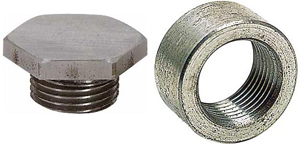
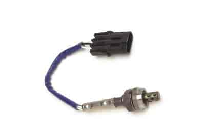
Each side has 2 different shaped wiring connectors and the front and rear 02s have a matching connector shape so they cannot be connected in wrong UNLESS someone has hacked the 02 wires and used the wrong connector or incorrect wiring order.
Look at the stock 02 sensors and it will be clear which shape they have and match to the main wiring harness.
If you are wrongly using the rear 02 connectors for the fronts then they are on the wrong side of engine as the right rear connector is for the left rear 02 and same for left side is for right rear 02.
Using a OBD-II scanner would quickly tell you the state of the 02 sensors and wacked fuel trims would point to 02s in the wrong placement"
placing them in the primary tube of a header limits the sample to the related cylinder, placing it in the collector samples the average of that cylinder head, if you were to place it in the (H) or (X) pipe you would get the average for the whole engine and loose a good deal of your diagnostic info as to the location or cause of a fuel/air variation, now the heated wide band style seems to work fine in the header collectors and Id place the sensor in the most easily accessible location you could, about mid collector, the narrow band single wire style should be placed in the collector as close to the primary pipes as practicable, but remember the narrow band tend to read accurately only near a fuel air ratio of 14.7:1 while the wide band heated O2 sensors are more accurate over a wider range of fuel/air ratios and keep in mind you want the wires routed so road trash won,t bust/snag the wires and the wires won,t burn on the hot exhaust pipes.
bungs can be welded to header collectors, in several locations
http://www.jegs.com/i/JEGS/555/30742/10002/-1
http://www.jegs.com/i/JEGS/555/30747/10002/-1
http://www.jegs.com/i/Edelbrock/350/3591/10002/-1
it helps if you understand that oxygen sensors do not measure your true fuel air ratio,entering the engine, but instead measure the remaining oxygen content of the burnt exhaust gases,and there are both narrow and wide band sensors
INFO OFF THE NET
"
The O2 sensor generates voltage in the range of about 0 to 1 volts. Higher voltages (greater than 0.5 volts) means there little or no O2 in the exhaust and indicates a rich mixture. Lower voltages (less than 0.5 volts) means there is a lot of O2 in the exhaust and indicates a lean mixture.
Check the number of "O2 cross counts" with a scan tool. This is the number of times the O2 sensor voltage crosses 450 mV in a sample period (which I believe is 10 seconds). The higher this number is the better. I think a good minimum is 10 but hopefully you'll see values above 20.
Although they don't last forever, O2 sensors are frequently replaced when still good. But if yours has white deposits on it,or its wet black and oil coated it's probably contaminated.
If you remove your O2 sensor and decide to reinstall it, make sure to use some of the special high heat anti-seize (which is made out of tiny glass beads). New sensors come with it pre-applied. (But if you install and remove a new sensor, you need to apply more anti-seize!) The stuff I use is AC/Delco High Temp Anti-Seize Compound (part 5613695).
O2 sensors are another part your local AC/Delco distributor has cheaper than the dealer"
http://www.carcraft.com/techarticles/cc ... to_04.html
http://www.carcraft.com/techarticles/cc ... index.html
http://www.diyautotune.com/
viewtopic.php?f=44&t=469&p=6061&hilit=scan#p6061
You cannot turn OFF the rear 02s, only turn off their error codes from tripping.
Bad idea not using the rears as they also are used by the PCM to compute the fuel trims
racingvette posted this additional info
"As per GM :
The rear oxygen sensor, located after the catalyst, is used for fuel trim corrections on OBD-II vehicles. By virtue of its location, the rear sensor is generally protected from high temperatures and much of the contamination that affects the front oxygen sensors.
In addition, the rear sensor sees exhaust gases that are equilibrated – they have already been converted by the catalyst so that there is very little residual oxygen.
This allows the rear sensor to respond to much smaller changes in exhaust gas oxygen content. In turn, it then possible for the rear sensor voltage to remain near the 0.45 volt switchpoint.
This characteristic allows the rear sensor to be used for fuel control. Under steady rpm and load conditions, the short term fuel trim bias can be adjusted so that the rear sensor voltage is maintained near the 0.45 volt switchpoint.
This ensures that the catalyst is getting a stoichiometric exhaust gas mixture, despite any shift in the front sensor switchpoint.
The rear fuel trim corrections are learned in KAM (Keep Alive Memory).
Internally, this system is known as Fore Aft Oxygen Sensor Control (FAOSC). Note that FAOSC learns and reacts very slowly because the catalyst, with its large/slow oxygen storage and release characteristic, is part of the control loop. Also, this system cannot be used with a "y-pipe" exhaust where a single rear sensor would try to adjust dual front sensors.
Rear O2s if you will are a fine tune of the commanded fuel flow but are very much part of the model used in the PCM's math to correct AFR for closed loop
This means running no rear O2s or Simms will effect how the PCM computes what the fuel trims are.
There is 2 02 wiring connectors per side on frame rail
Each side has 2 different shaped wiring connectors and the front and rear 02s have a matching connector shape so they cannot be connected in wrong UNLESS someone has hacked the 02 wires and used the wrong connector or incorrect wiring order.
Look at the stock 02 sensors and it will be clear which shape they have and match to the main wiring harness.
If you are wrongly using the rear 02 connectors for the fronts then they are on the wrong side of engine as the right rear connector is for the left rear 02 and same for left side is for right rear 02.
Using a OBD-II scanner would quickly tell you the state of the 02 sensors and wacked fuel trims would point to 02s in the wrong placement"