I found this question posted else ware (quote below) and just for giggles I ran the info data through the math and as is very common,
its rather obvious that the guy posting this, is looking at cams that have a good deal longer duration and more lift than the engine is likely to run correctly with.
now he may make very good peak power with the cams he listed, but he will sacrifice a bit of low and mid range torque that the properly matched cam would provide that would still produce very good peak power.
FROM PAST EXPERIENCE , IF YOUR GOAL IS MAX POWER, I'D SUGGEST A CYLINDER HEAD THAT FLOWS IN THE 350 + CFM RANGE AT .600-.650 LIFT.
THE 496 DISPLACEMENT AND 10.5:1 COMPRESSION WILL PROVIDE PLENTY OF OFF IDLE TORQUE FOR STREET TIRES SO A SINGLE PLANE INTAKE WOULD BE FINE
anytime you start to assemble a list of matched components where your intent on building that engine to meet a certain power and rpm limitations you need to mentally step back and do the math thats required to keep all the parts you select , are kept with-in that intended power and rpm range, and while looking closely at both the financial budget and the component stress limitations, and you'll need to keep in mind fuel octane youl use,and the drive train gearing and vehicle weight ,and the probable durability and traction limits its likely to be used under.
If youll spend 90% of your engines operational life at under 5800 rpm it makes very little sense in my opinion to build the engine for peak power over about 5800 rpm, just for a couple hp you,ll very seldom have access too, it ,makes more sense in my opinion to concentrate on durability and drive ability, in that 3700 rpm-6000 rpm youll need 90% of the time, and maximizing the torque curve,
yes you could use some of the better flow rate, 280cc-290cc oval port heads to get a bit more low and mid range torque but at a minimal reduction in peak power
Btw heres a tip learned through experience , if your 496 -540 displacement BBC combo includes an engine with at least 10:1 compression and a cam with at least 240 duration at .050 lift, and oval port heads, youll almost always find a single plane intake has some advantages over a dual plane intake.
https://www.holley.com/products/intakes/single_plane_manifolds/parts/7620
![7620_2[583x].jpg](/proxy.php?image=http%3A%2F%2Fwww.grumpysperformance.com%2Fjuly2017%2F7620_2%5B583x%5D.jpg&hash=5931892943d24f9505466692c10aa541)
the 10.6:1 compression results in calcs that show that the intake valve should seat at about 70- 73 degrees past bdc and intake duration should be in the 240-245 range with exhaust duration maybe 5-7 degrees longer and a 105-106 lca, this is very likely to limit lift to the low to mid .580-.600 range in a hydraulic roller cam, if your want to maintain, a reasonably long and trouble free use as daily transportation.
IF you wanted to use the cams listed in the link boosting the compression too between 11.5:1-to 12:1 and use of race octane fuel would be required, to allow the full potential.
a 496 bbc will generally use a port cross sectional area near 4 sq inches.
this will place you in the larger oval port and smaller rectangle port standard bbc head configuration range.
when you see guys selecting long duration cams in a 496 BBC with only 10.7:1 compression thats intended to be used with pump octane high test fuel, they are generally trying to compensate for poor flowing cylinder heads, adding duration allows more time for the ports to flow but results in a lower effective dynamic compression ratio.
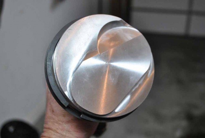
what length connecting rod and what piston pin height are you using, building the 496 BBC?
yes Im assuming its a tall deck 10.2" block and a 4.25" stroke
a 4.25" stroke,6.8" rod and 1.270 pin height, for that 10.2 deck height block
6.8" rod divided by a 4.25" stroke=1.6 ratio
displacement = bore x bore x stroke x 8 x .7854
1/2 stroke + rod length+piston pin compression height,
should roughly equal block deck height ,
plus or minus a few thousandths,
minor adjustments in compression,
due to head gasket thickness and what the piston deck height is are common
http://garage.grumpysperformance.co...-about-your-potential-dream-bbc-combos.14607/
http://garage.grumpysperformance.co...od-rod-length-too-stroke-info.510/#post-10311
http://garage.grumpysperformance.co...onnecting-rod-rod-length-too-stroke-info.510/
http://garage.grumpysperformance.com/index.php?threads/measuring-rod-and-pin-heights.3760/#post-9968
http://garage.grumpysperformance.com/index.php?threads/bbc-related-links-and-useful-info.17140/
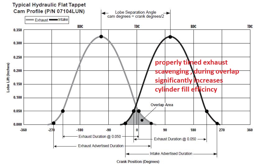
Id also point out that cam timing matched to the exhaust scavenging has a huge effect on potential intake flow rates
a good set of BBC heads with a 2.30 inch intake valve, header primary's 38" long with 2" pipes and 3.5" collectors about 20 inches long, can flow more than adequately for the 496 BBC that will rarely see over 6500 rpm in a street/strip engine combo.
keep in mind the cam timing must match the header design and displacement and dynamic compression, to fully allow the cams overlap period to match the intended power /rpm band and effective exhaust scavenging.
something rather similar to this cam used with 1.8:1 roller rockers would be my suggestion.
yes I'm well aware that 90% plus of the people reading this thread ,
won,t bother to read through the links and sub links,
but for the few who want the info they are
included
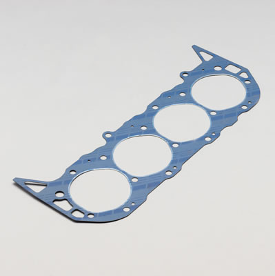
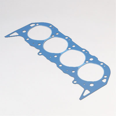
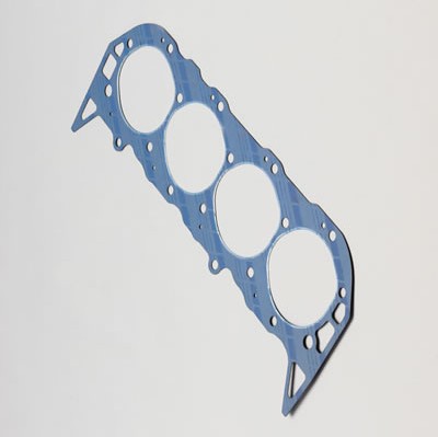
found this gasket over at summit..
using the correct head gasket too match the heads and cylinder heads your using on any big block chevy engine, is critical to prevent coolant loss, and maintain proper cooling
be aware that head bolts enter the block coolant passages,
so if you failed to dip the bolt threads in sealant when they were assembled,
through the heads coolant can seep up along the head bolts,
into the area under the valve cover
btw read this
both of these work great at sealing head bolt threads,IF you forgot to use thread sealant on the head bolt threads, why, not try to eliminate one potential area of concern,why not pull each head bolt one at a time and clean its threads dip the clean bolt in the can of sealant and re-install and re-tighten the individual bolt to the required torque, before removing the next bolt, I've done this in the past when guys failed too seal the bolt threads and its worked and there was no head gasket issues later, the only thing you have to loose by trying this is the cost of a can of thread sealant and an hour or two of your time, and of course you'll more than likely need to re-adjust valves as the rockers will need to be removed at some point in the process..
http://www.summitracing.com/parts/FE...2/?image=large
Brand Fel-Pro
Manufacturer's Part Number Q8180PT2
Part Type Head Gaskets
Product Line Fel-Pro Head Gaskets
Summit Racing Part Number FEL-8180PT-2
Bore (in) 4.370 in.
Bore (mm) 110.998mm
Gasket Material PermaTorqueMLS
Compressed Thickness (in) 0.039 in.
Compressed Volume (cc) 9.700cc
Lock Wire No
Quantity Sold individually.
FIRST GEN, SBC CLOYES ROLLER TIMING SET
https://www.summitracing.com/parts/clo-9-1100/overview/
MARK IV BBC CLOYES ROLLER TIMING SET 1965-90
https://www.summitracing.com/parts/clo-c-3024x/overview/
MARK VI BBC CLOYES ROLLER TIMING SET 1991-95
https://www.summitracing.com/parts/...-specific/engine-family/chevy-big-block-gen-v
According to summits apps page
The gasket your have fits
http://www.summitracing.com/parts/FP...ET&prefilter=1
Make CHEVROLET
Engine Type V8
Liter 6.5
CID 396
Engine Size 6.5L/396
Beginning Year 1966
Ending Year 1970
Engine Family Chevy big block Mark IV
Make CHEVROLET
Engine Type V8
Liter 6.6
CID 402
Engine Size 6.6L/402
Beginning Year 1970
Ending Year 1972
Engine Family Chevy big block Mark IV
Make CHEVROLET
Engine Type V8
Liter 7.4
CID 454
Engine Size 7.4L/454
Beginning Year 1970
Ending Year 1990
Engine Family Chevy big block Mark IV
read and pay attention to the linked info
http://www.superchevy.com/how-to/en...-big-block-casting-changes-through-the-years/
http://garage.grumpysperformance.com/index.php?threads/another-496bbc.5123/
it may be the result of a crack in the head or block or just an intake or head gasket leaking, issue, as stated change oil and filter ,
and if the problem returns you darn sure better track down the source before repairs get exponentially more expensive
some cracks won,t leak until the engine heat of the engine thats been running for awhile expands the metal.
if its not up too operating temp, theres no leak.
its not un-common for intake gaskets to leak coolant,
into the lifter gallery if they were not correctly installed or damaged, or intake manifolds to leak coolant,
if the coolant passages are corroded or improperly machined,
or too find coolant leaks if the wrong head gaskets were used.
Quote:
Coolant Routing Mk IV/Gen 5/Gen 6
There are two different ways that coolant can be routed through the engine: series flow and parallel flow. Both ways work just fine. There may be a slight preference for parallel flow, but it is not a big deal. Series flow has the water exiting the water pump, flowing through the block to the rear, it then transfers through the head gasket and into the cylinder head through two large passages on each cylinder bank at the rear of the block. The coolant then travels from the rear of the head, forward to the front of the head, into the intake manifold water passage and out past the thermostat and thermostat housing. The water cools the block first, then it cools the head. The coldest water (coming out of the water pump) is directly below the hottest water (having already picked up the heat of the block and the head) as the hot water transfers into the intake manifold. By contrast, parallel flow has the water exiting from the water pump into the block, where a portion "geysers" up into the head between the first and second cylinder, another portion "geysers" up to the head between the second and third cylinders, another portion geysers up to the head between the third and fourth cylinder, and the remainder transfers to the head at the rear of the block. The coolant temperature inside the engine is more even that way. The differences in coolant routing is having (or not having) the three additional coolant transfer holes in each block deck, and three matching holes in the head gasket. The heads have passages for either system, and are not different based on coolant flow.
Be aware that gaskets that DO have the three extra holes between the cylinders often have restricted coolant flow at the rear--instead of having two large coolant transfer holes at the rear, there is only one, and it's the smaller of the two holes that remains. This is important because if you use a parallel flow head gasket on a series flow block, you can have massive overheating and there's NOTHING that will cure the problem except to replace the head gaskets with ones that don't restrict flow at the rear of the block, or to drill the block decks to allow the coolant to flow into the head between the cylinders. Here's why they can overheat: A series-flow block doesn't have the openings between the cylinders, no coolant can flow up to the head there. The gasket may only have the single, smaller opening at the rear, so the amount of water that gets through that opening is greatly reduced from what the block designers intended. The result is that the coolant flow through the engine is only a fraction of what is needed.
Most, but NOT all Mk IV engines are Series Flow. ALL Gen 5 and Gen 6 engines are Parallel Flow. A series flow block can be converted to parallel flow by drilling 3 holes in each deck surface, and then use parallel flow head gaskets. You can use the parallel flow gaskets as templates for locating the additional holes. It's really easy: Put the parallel flow gaskets on the block, mark the location and size of the three extra holes. Remove the gasket. Grab a 1/2" drill and a drill bit of the correct size, and pop the extra holes in the block. There is NO modification needed on the head castings. Some blocks have one of the holes already, but it needs to be ground oblong to properly match the gasket. Again, very easy with a hand held die grinder and rotary file.
I'd assume the intake gaskets are the source until proven otherwise.
but be aware that miss matched head gaskets, to the heads and block combo in use, can cause several issues
don,t assume the worst, just logically and step by step track down and correct the issue using FACTS.
The Gen V was first installed in the 1991 year models.
The earliest casting I've decoded was a very late (Nov/Dec?) 1989 date.
The Gen VI was first installed in the 1996 year models.
The cams for the Mark IV and Gen V are interchangable for flat tappet lifters.
The Gen VI where the first equiped with Roller Lifters, but the main difference is the machined flats on the lifter bores of this block - you can still install an earlier cam without rollers.
The cam retainer plate holes are verticle on a Gen V~VI, rotated 90deg from the Mark IV's horizontal orientation.
The '91 on trucks with Gen V's had manual transmissions and use a bracket for the pivot, the later medium duty trucks have a hydraulic clutch.
The Gen blocks use longer main cap bolts than the Mark blocks.
The crank on the Gen engines uses one long key in the keyway slot for the cam drive gear and the damper - the Mark cranks have two short keyway slots and two seperate keys, one for the cam gear one for the damper.
As he stated, Gen cranks are one-piece seal, Mark are two-piece.
The Flex plates are interchangeable - but Flywheels, for truck and marine applications, are not interchangeable on Mark and Gen engines.
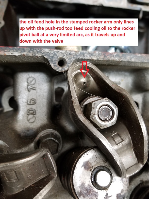
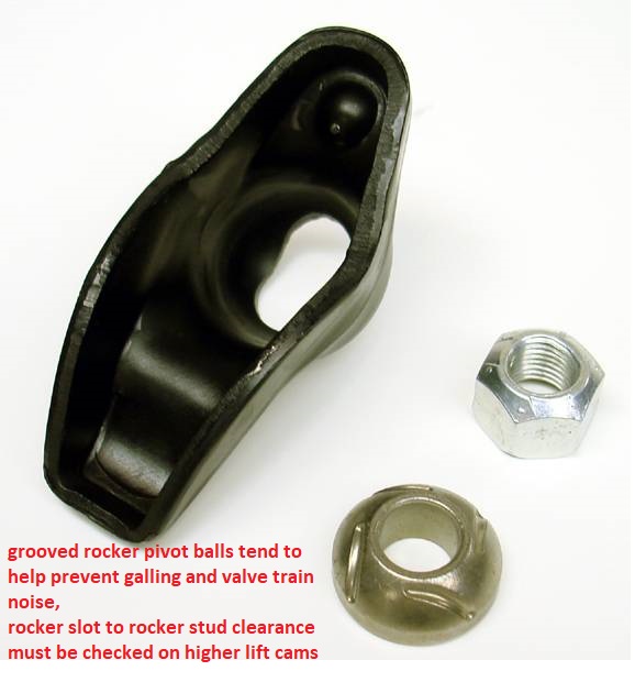
KEEP IN MIND, MANY PEOPLE THAT HAVE BROKEN ROCKER STUDS HAVE FAILED TO VERIFY THE PISTON TO VALVE, CLEARANCES, ROCKER STUD TO ROCKER SLOT CLEARANCES,AND SPRING BIND CLEARANCES, etc.
it takes hundreds of pounds of force to bust rocker studs and or bend push rods, if you have those issues STOP AND LOCATE the geometry or CLEARANCE ISSUES CAUSING THE PROBLEM
theres several manufacturers and models available , heres a basic 1.5:1 ratio SBC version.
http://www.summitracing.com/parts/lun-85025
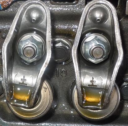
the grooved rocker pivot ball design was an effort by G.M. engineering to economically solve the issue of marginal oil flow causing rocker ball galling, and resulting noisy, or broken valve trains
FAILING TO READ THE LINKS WOULD BE A BIG MISTAKE HERE!
http://www.chevydiy.com/gaskets-fasteners-guide-big-block-chevy-engines/
http://www.superchevy.com/how-to/4567-chevrolet-big-block-engine-generations/
http://hotrodenginetech.com/top-10-reasons-to-build-gen-vi-based-big-blocks/
http://garage.grumpysperformance.co...-brief-big-block-chevy-history.951/#post-5878
http://garage.grumpysperformance.com/index.php?threads/another-496bbc.5123/
HEADS LIKE THIS WOULD BE A DAMN GOOD MATCH
http://www.airflowresearch.com/305cc-bbc-rectangle-port-cylinder-head/#specs (best)
http://www.jegs.com/i/Brodix/158/2061015/10002/-1 (ok)
https://www.summitracing.com/parts/nal-12363400/overview/ (OK)
https://www.summitracing.com/parts/tfs-41410001-m22/media/chartsandguides
http://www.compcams.com/Company/CC/cam-specs/Details.aspx?csid=584&sb=2
IF you have the newer mark V-or- VI ,1 piece rear seal block,
a forged scat rotating assembly similar too this, with the correct pistons, rings etc. might be used
https://www.summitracing.com/parts/sca-1-42460bi/applications
http://garage.grumpysperformance.com/index.php?threads/dynamic-vs-static-compression.727/
http://www.wallaceracing.com/runnertorquecalc.php
http://garage.grumpysperformance.com/index.php?threads/port-speeds-and-area.333/
http://garage.grumpysperformance.com/index.php?threads/crowers-valve-timing-charts.4299/
http://garage.grumpysperformance.com/index.php?threads/semi-fool-proof-cam-sellection.82/
http://www.wallaceracing.com/header_length.php
http://www.hotrod.com/articles/big-block-chevy-intake-cylinder-head-dyno-test/
http://www.superchevy.com/how-to/project-cars/sucp-1001-complete-chevy-big-block-build-testing/
http://www.chevydiy.com/how-to-build-chevy-big-blocks-intake-manifold-guide/
https://www.profilerperformance.com/206J-bbc-single-plane-intake.html
http://garage.grumpysperformance.com/index.php?threads/is-backpressure-hurting-your-combo.495/
http://garage.grumpysperformance.co...gine-to-match-the-cam-specs.11764/#post-55651
http://garage.grumpysperformance.co...y-in-building-a-good-engine.11682/#post-54682
http://garage.grumpysperformance.com/index.php?threads/port-speeds-and-area.333/#post-51660
http://garage.grumpysperformance.co...-calculators-and-basic-math.10705/#post-50173
ID call holleys tech guys for the correct 950cfm-1050 cfm dominator carb
https://www.holley.com/products/fuel_systems/carburetors/dominator/

(Words and photos by Scott Liggett) – We know many Bang Shifters are not made out of money. We are in that crowd ourselves. Any way we can save money on our project cars allows us to have a better car or truck. The easiest place to save money using our time and sweat instead of paying shop labor rates. One place many people often over look is the assembly part of rebuilding an engine.
Sure, there are few that have access to the tools necessary to do machine work on our engines, but putting together an engine doesn’t require fancy tools. A good torque wrench is about the only fancy tool that we needed putting together a 454 we recently had machined for a rebuild. Since we were getting estimates up to $500 from machine shops to assemble our engine, we decided that we save that money by taking the time to do it ourselves. That is just putting the new parts and machined block, crank and rods back together.
Yes, we were a bit apprehensive to do it. Engines are not cheap to get built these days. That can scare many people away from attempting this kind of work. But, after talking to some friends and our machine shops, we decided to go for it.
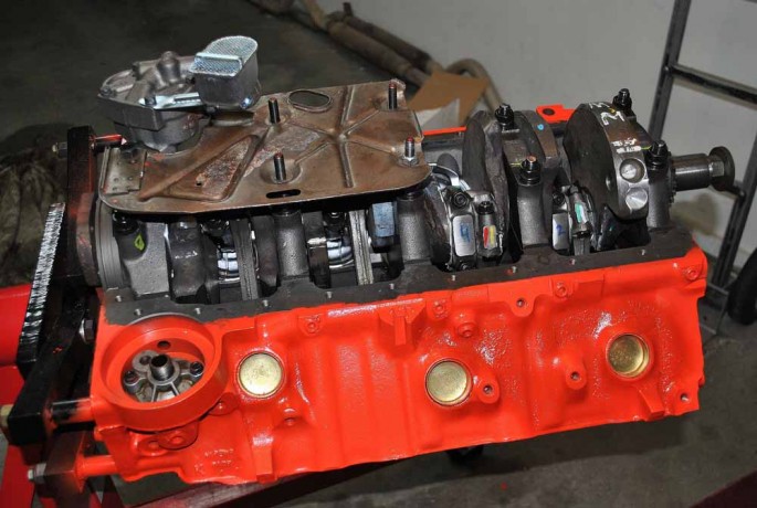
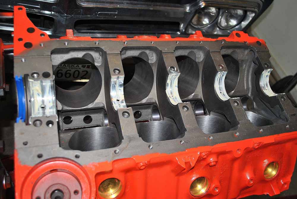
Truth be told, this is our second time assembling this 454 after machine work. But, the reasoning for this had nothing to do with the machine work done, or assembly job. We had two things that had us pulling the engine again after only 10,000 miles. First, we had constant lifter noise after the engine warmed up. Second,was piston slap from only doing a dingle ball hone with the original pistons with new rings and bearings. All the lifters failed a bleed down test and the pistons had too much clearance after the home honing job. This time we bought new pistons and had the block completely machined top to bottom with a .030 over bore. The rotating assembly had to be balanced for use with the new pistons.
You want to work in as clean as space as possible to avoid debris getting into your fresh engine. We were working in Scott’s one car garage at his house, which is pretty clean. We kept the engine covered by old, but clean towels in between days we were working on the engine.
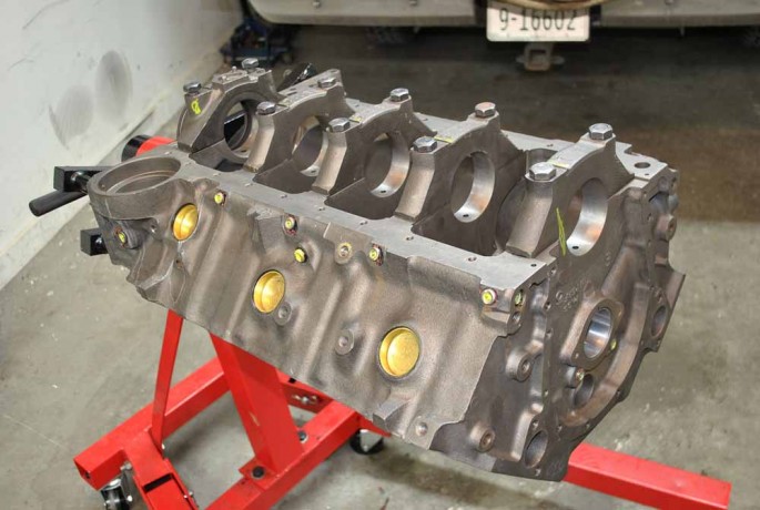
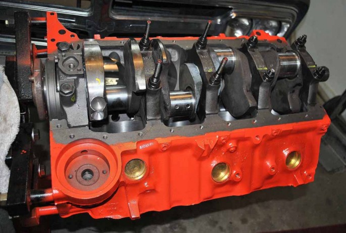
This is how we received our 454 block back from the machine shop. The guys over at BluePrint Engines did the work for Scott and the block came back looking like a brand new casting, not like a 45 year old block. In case it isn’t obvious, the first thing to do is to get it on an engine stand. We got our from Harbor Freight, but this one is the big dog. A fully dressed 454 weighs near 700 lbs. They also replaced all the freeze and galley plugs for us.
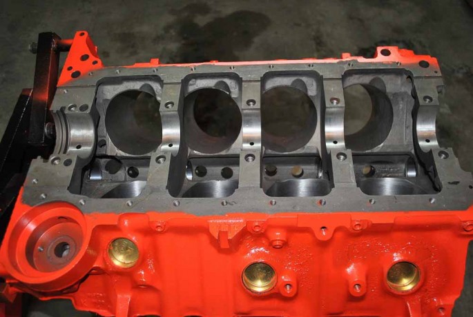
After taping off the areas we didn’t want painted, we shot the engine in Chevy Orange. We were told not to paint in the oil filter housing, so we took some time to clean that up later in the build.
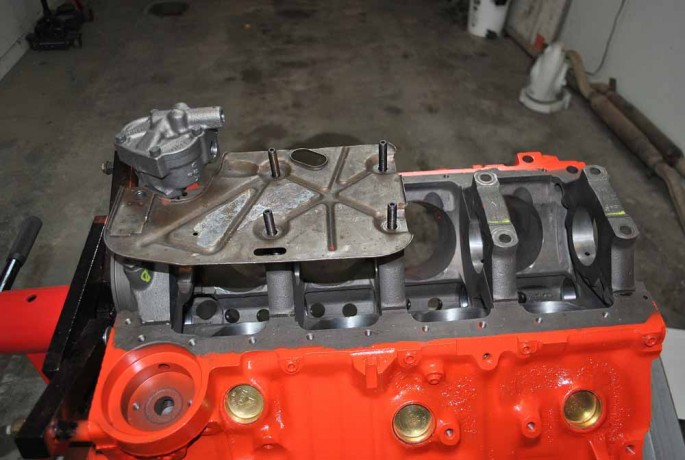
Before doing any assembly, we decided to see if our factory windage tray would work with the Milodon 7 quart oil pan and Melling high volume oil pump we are using. We also decided to upgrade to ARP main studs instead reusing the original main bolts for better support for the crank. The studs have provisions for the windage tray.

Even though the Milodon pan has these dimples to make room for the studs, we had to dimple them a bit more so the pan would sit flush on the block.
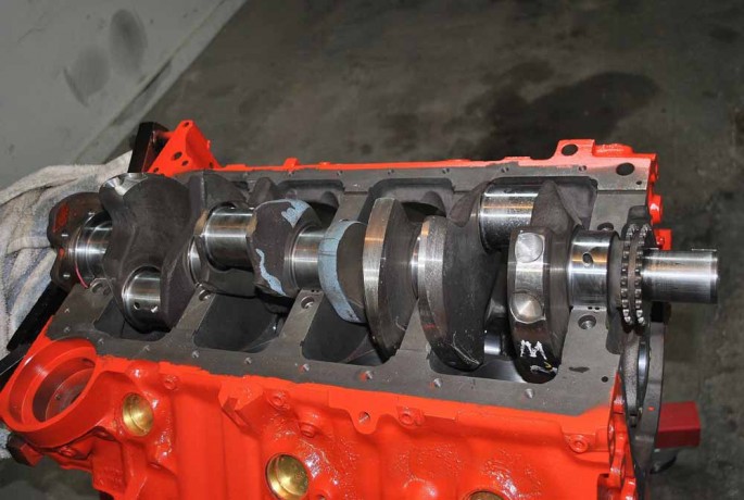
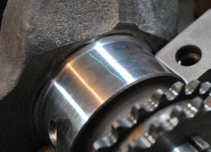
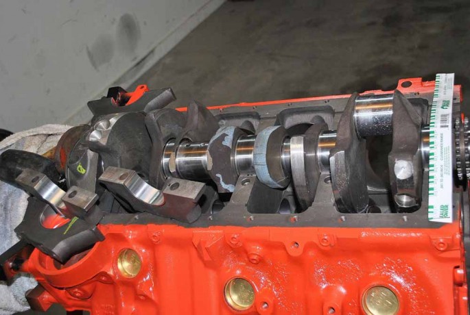
BluePrint Engines did the crank turning and balancing for us as well. The crank was standard when we took it to them, but polishing did not get all the scratches out of the bearing surfaces, so we had it turned .010/.010. They balance all their rotating assemblies below 2 grams, but ours came out .41 grams on the front and .89 grams on the back. We first laid in the block sides of the main bearings and carefully laid the crank in the block without any assembly lube at this point. Forged big block cranks weigh in excess of 60 pounds, so if you can get help to set it in the block, do so. Dropping it on your bearings, or your foot, would not be good.
Next, we cleaned the main caps with Brakleen and a lint free rag before installing their half of the main bearings. Even though the block was thoroughly washed after machining, their was still some dirt after sitting around for two weeks before getting to work on it. The rear main seal is not needed at this point.
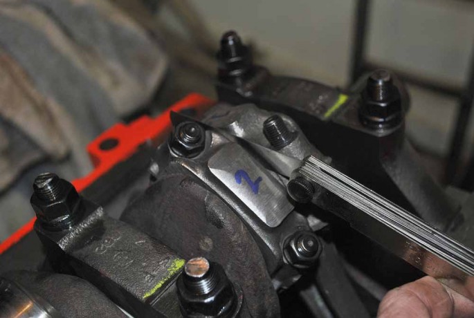
We got some Plastigauge from the local parts store to double check bearing clearances. Your machine shop should have done this during the machining process with their measurements. You are just making sure. Taking your time and being anal during engine assembly is a good thing. After laying the piece of waxy, plastic string across the bearing surface on the mains, you place the main caps on and torque them down to manufacture specs. In the case of our 454, it was 105 ft lbs.
Next, remove the main caps and check the measurements on the Plastigauge’s paper cover. Our Chevy Factory Overhaul Manual says that the main should have between .001 and .003 clearance. All of our mains had .015 readings. This is only approximately, but you are being sure of what you got before you have the engine together and running. The alternative is finding bearing material in your oil filter after a few miles. Not a good day. Repeat this process on all of the main caps and bearings.


Remove the crank from the block, then get out your engine assembly lube and liberally cover the main bearings. Then, you need get out the rear main seal from your engine gasket set. Fel-Pro includes instructions on which way it is suppose be installed to keep it from leaking all over your driveway.
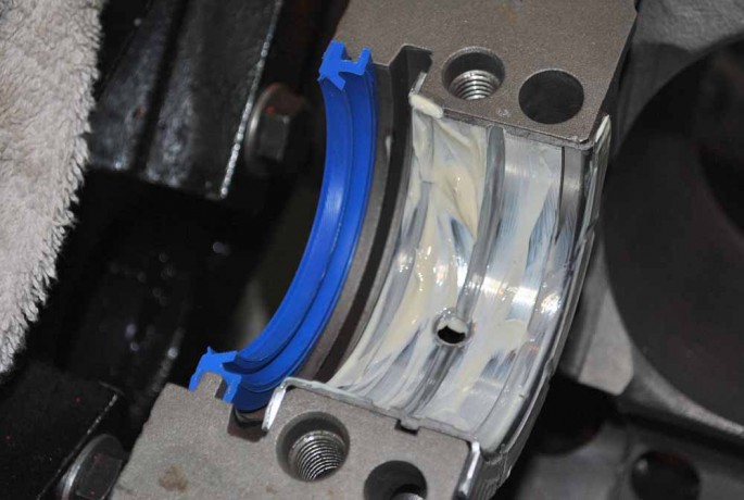
Some people say you should install the rear main seal halves offset slightly for better leak protection. Others don’t. We did.. We did add a little bit of RightStuff sealant on the seal ends for added security.
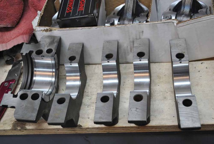
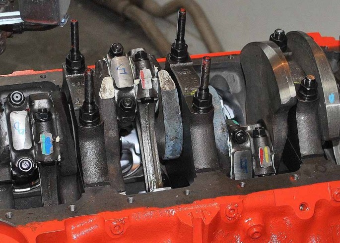
Now your crank is done. Time to move on the connecting rods and pistons. We used the same plastigauge on each of the rod bearings to check their clearances as well.

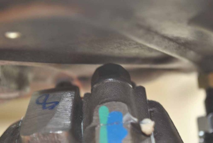
For the purpose of checking the bearing clearances with the pistons already installed on the rods, we did this before installing the rings on the pistons. This made sliding them in and out of the bores much easier. The rods were stamped with their numbers when Scott took the engine apart before machining, but he wrote big numbers on the end caps cause he is slowly going blind like all middle aged men. The machine shop added those colored paint dabs as part of their checks and rechecks. They mark the side of the rod that has the rod bearing tabs. The tabs should face towards the outer part of the block.
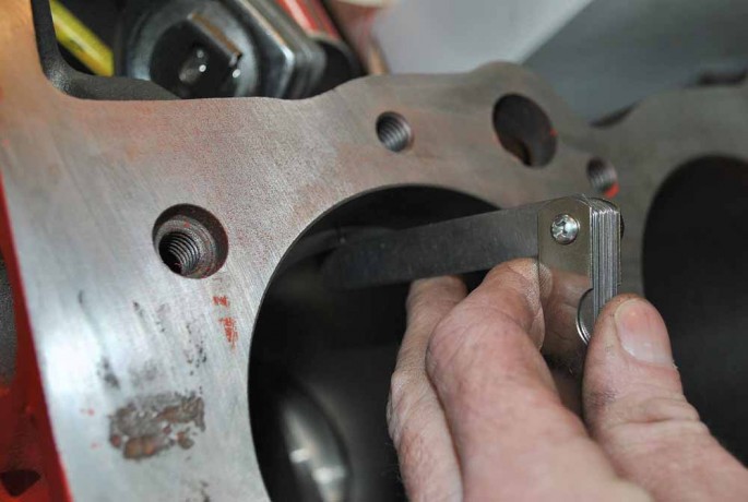
Torque the rod bolts to their recommended specs. Before removing the rod caps and checking the clearances with the plastigauge you used, check the side clearances on the rods. We checked between the rod pairs and between the rods and the crank sides. On our 454, those clearances should be between .015″ and .021″. Bearing clearances on our 454 is the same as mains, .001″-.003″.

After checking the rod clearances were all good, we moved on to installing the rings on the pistons. Even if you buy rings that are supposed to be pregapped, we suggest you check the clearances anyways. Remember what we said about being thoroughly anal? Our rings came with our piston set from Keith Black. They are moly rings, but we had to gap them. It is tedious, but necessary. Too tight of clearances and you will break them and the ring lands on the pistons. Too loose and you can have oil usage problems and lack of power. We wanted to get consistent measurements, so we always made sure they were the same distance down in the bores each time.
Using a feeler gauge find the clearance on the ring. The measurement will depend on the type of rings you are using and the intended purpose of your engine. The use of nitrous and boosted engines need more clearance for the added cylinder pressure and heat. We wanted .021″ on the top ring, and .024″ on the second ring.
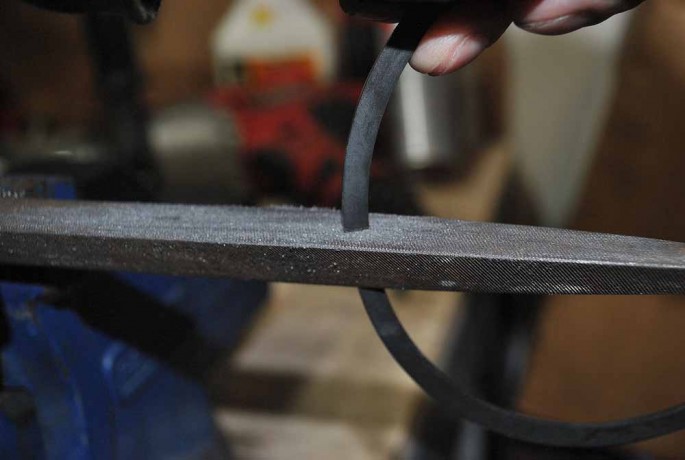
Our rings needed a bit of filing. here are ring gapping tools available from many companies, but we put a metal file in the bench vise and gently ground them a bit. Do a little bit at a time. Don’t get in a hurry. It’s better to go back to the file a few times, then over gap your rings.
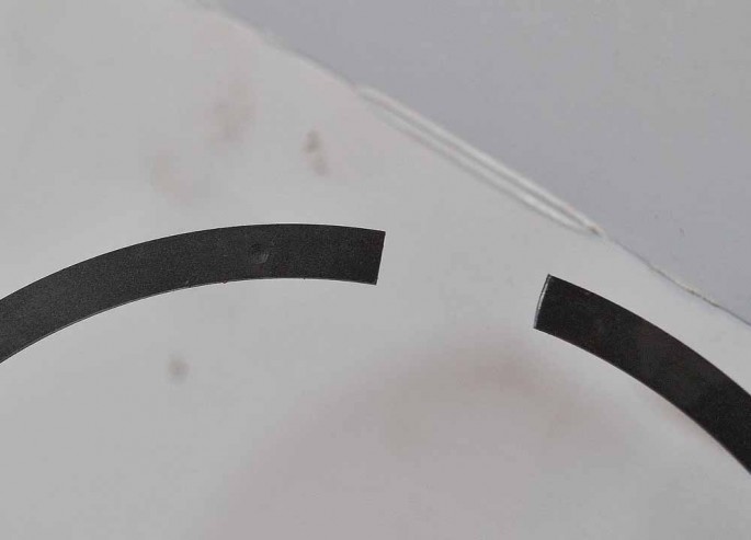
Once all 16 rings are gapped, they need to be installed on the pistons. Certain types of rings are reversible. Ones that are not often have a dot to which side is the top. Keith Black’s instructions said not spiral them onto the pistons. This means we needed to spread the two ends apart in order to get the rings on the pistons. There are many inexpensive tools for safely doing this. We should have gotten one ourselves as we got impatient and broke one of the rings trying to install it. The oil rings are the easiest to install and are usually three pieces.
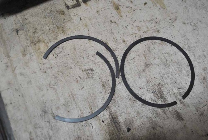
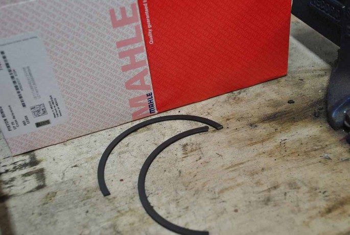
Since ring sets don’t come with spares, we had to order another set. We were able to get another set of the same style and material from another brand, but it will work.
Clock the rings 180* apart before moving on to installing the pistons and rods in the engine for the last time.

Now that there are piston rings on your pistons, getting them into the block is a little more work. So not damage the bearing surfaces on your crank, cover the rod bolts with rubber hoses or specific boots so not to scratch crank. We just used 3/8″ fuel line.
Now, it’s time to install your rods and pistons for the last time. You will need a ring compressor. There are fancy, size specific ones available. We just used this $18.00 one we got at Napa. Set the rod into the bore, then tap the compressor flush with the deck surface of the block. Be sure the valve reliefs in the pistons are oriented in the correct direction.
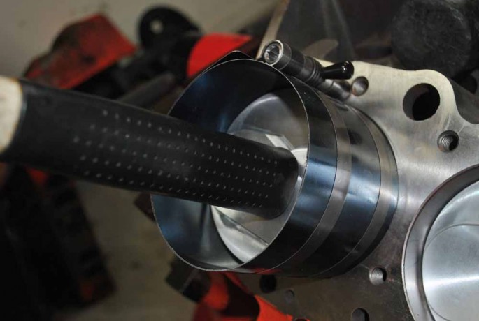
We used the rubber handle of a ballpeen hammer to tap the piston down into the bore. A dead blow, or a specific dead blow piston driving tool will work as well. Just do not use anything metal against the piston face. That would be bad.

With this type of ring compressor tool, you do need to stop a couple of times during the piston installation to be sure the compressor stays flush with the deck surface. If the piston ring slips out, you will be starting over.
Use the engine assembly lube on the rod bearing halves just like the main bearings. When you get the piston driven down to where the rod meets the crank throw, put the rod cap on the rod and tighten the bolts down to recommended specs. Our ARP rod bolts were torqued to 50 ft lbs.
You will need to install your oil pump next. Don’t forget the oil pump pickup screen as well. We are using a Melling high volume pump and a pickup screen for use with a 7 quart oil pan. This pickup screen is pretty much dummy proof in it’s installation. We still checked for it’s clearance to the bottom of the oil pan. Before installing the oil pump, make sure you install the oil pump drive shaft first, or the day you fire up your engine will not be a good day. The oil pump’s bolt gets torqued to 60 ft lbs on our 454. The rotating assembly installation is complete.
We took some extra time to install our factory windage tray for better oil control and a few more horsepower. Our ARP stud kit included the four longer studs for its use. Be sure to check the rod clearance under the windage tray. Rotating parts need at least .060″ clearance.
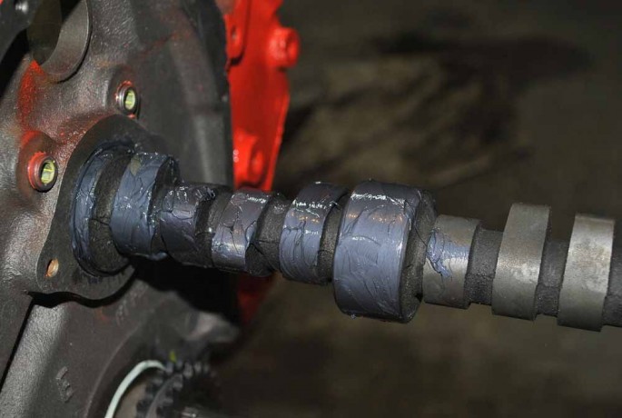
Flip the engine back over for the camshaft installation. Apply liberal amounts of moly lube to the camshaft lobes and bearing surfaces. We only add the moly lube to four lobes and a bearing surface at a time, then install the cam up to that point. Then add some more to the next set of four. The keeps your hands cleaner and it easier to install. We used a 5/16″ x 6 inch long bolt in the front of the cam for more leverage. Or, you can buy a cam handle. We’re cheap.

We used this cam moly lube we got from Isky. This tub has been used on five or six cams and we still have plenty left.
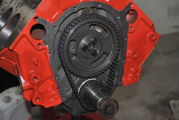
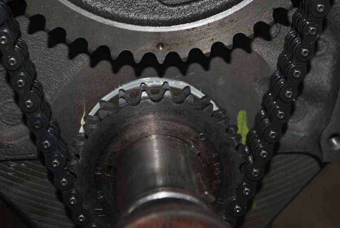
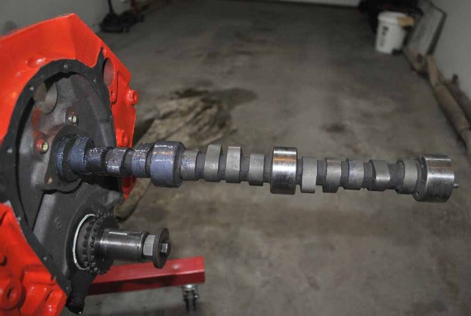
The last thing to do is install the timing chain. First, drive the crank gear on the crank with the round dot on the crank key way and the dot pointing straight up. The cam gear goes on with the dot pointing straight down. This Cloyes timing set has a three way set up for advancing, or retarding the cam 4*. We installed ours straight up.
That’s it for the short block. The cam’s lifters will go in with the pushrods and valvetrain. It wasn’t all that hard, was it? We did this over a weekend.
http://www.hotrod.com/how-to/engine/0806phr-chevy-496-big-block-engine-build/
http://www.dragzine.com/news/probe-industries-496ci-pistonsstroker-kits-for-big-blocks/
http://idealhowtovideo.com/bigblock80006.htm
http://www.superchevy.com/how-to/project-cars/sucp-0312-496-street-bruiser/
http://www.twperformanceparts.com/index.php?route=product/product&product_id=5302
http://www.twperformanceparts.com/index.php?route=product/product&product_id=3910
http://www.superchevy.com/how-to/project-cars/sucp-0901-496-chevy-big-block-build/
http://www.superchevy.com/how-to/engines-drivetrain/1407-642-hp-budget-iron-head-build/
http://garage.grumpysperformance.co...-articles-you-might-want-too-look-over.14682/
http://garage.grumpysperformance.com/index.php?threads/build-a-496-stroker-bbc.101/
http://www.superchevy.com/how-to/engines-drivetrain/1005chp-496ci-engine-build/
http://www.ebay.com/itm/Step-by-Ste...Big-Block-Engine-2-Disc-5Hr-DVD-/370654732889
http://garage.grumpysperformance.co...im-good-to-go-on-valve-clearance-right.15160/
http://www.superchevy.com/how-to/en...estech-performance-496-chevy-big-block-build/
http://www.hotrod.com/how-to/engine/116-0703-big-block-chevy-engine-build/
like with most performance parts and applications the critical part of the build,
is generally in selecting the correct components for that particular application,
and in assembling those components correctly with the correct clearances.
its always a multi layered process,
you can,t expect sub-par or weak parts to withstand the shock and torque and rpm/impact loads.
you can,t also expect improperly installed or clearanced or insufficiently lubricated or cooled parts to last very long under loads.
obviously the process REQUIRES the person doing the work, or assembly to do some in depth research,
and have any tools or measuring devices that will be needed.
the sub links contain a wealth of info
http://garage.grumpysperformance.com/index.php?threads/a-few-basic-precision-tools.16344/
http://garage.grumpysperformance.co...tion-of-crank-durring-short-blk-assembly.852/
http://garage.grumpysperformance.com/index.php?threads/bearing-clearances.2726/
http://garage.grumpysperformance.co...d-rod-orientation-clearance-issues-etc.16027/
http://garage.grumpysperformance.co...ng-rod-bolt-stretch-preload.11050/#post-85102
http://garage.grumpysperformance.com/index.php?threads/another-496bbc.5123/
http://garage.grumpysperformance.co...-building-a-peanut-port-big-block-combo.2900/
http://garage.grumpysperformance.com/index.php?threads/bbc-build-advice.15921/
http://garage.grumpysperformance.co...e-springs-and-setting-up-the-valve-train.181/
http://garage.grumpysperformance.co...-on-the-cheap-well-to-start.11739/#post-55478
http://garage.grumpysperformance.co...y-in-building-a-good-engine.11682/#post-54682
http://garage.grumpysperformance.com/index.php?threads/bearings-and-oil-flow.150/
http://garage.grumpysperformance.com/index.php?threads/oil-system-mods-that-help.2187/
 blog.dartheads.com

 www.motortrend.com
 www.enginelabs.com
its rather obvious that the guy posting this, is looking at cams that have a good deal longer duration and more lift than the engine is likely to run correctly with.
now he may make very good peak power with the cams he listed, but he will sacrifice a bit of low and mid range torque that the properly matched cam would provide that would still produce very good peak power.
FROM PAST EXPERIENCE , IF YOUR GOAL IS MAX POWER, I'D SUGGEST A CYLINDER HEAD THAT FLOWS IN THE 350 + CFM RANGE AT .600-.650 LIFT.
THE 496 DISPLACEMENT AND 10.5:1 COMPRESSION WILL PROVIDE PLENTY OF OFF IDLE TORQUE FOR STREET TIRES SO A SINGLE PLANE INTAKE WOULD BE FINE
anytime you start to assemble a list of matched components where your intent on building that engine to meet a certain power and rpm limitations you need to mentally step back and do the math thats required to keep all the parts you select , are kept with-in that intended power and rpm range, and while looking closely at both the financial budget and the component stress limitations, and you'll need to keep in mind fuel octane youl use,and the drive train gearing and vehicle weight ,and the probable durability and traction limits its likely to be used under.
If youll spend 90% of your engines operational life at under 5800 rpm it makes very little sense in my opinion to build the engine for peak power over about 5800 rpm, just for a couple hp you,ll very seldom have access too, it ,makes more sense in my opinion to concentrate on durability and drive ability, in that 3700 rpm-6000 rpm youll need 90% of the time, and maximizing the torque curve,
yes you could use some of the better flow rate, 280cc-290cc oval port heads to get a bit more low and mid range torque but at a minimal reduction in peak power
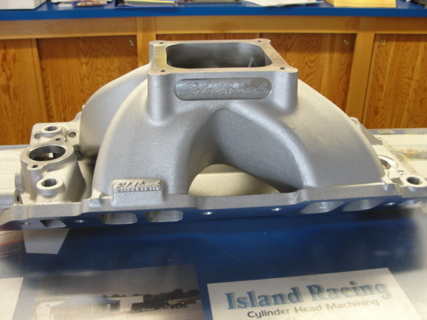
Btw heres a tip learned through experience , if your 496 -540 displacement BBC combo includes an engine with at least 10:1 compression and a cam with at least 240 duration at .050 lift, and oval port heads, youll almost always find a single plane intake has some advantages over a dual plane intake.
https://www.holley.com/products/intakes/single_plane_manifolds/parts/7620
I have rebuilt the 496 lower end with scat forged rotating assembly. -20 dome forged wiseco pistons, with 119 cc heads, compression will be 10.6:1. I'm torn between two cams. Stick shift, so no flashing to think about./4.10 gears/29" tyres. Wondering if the duration will be weak with the extra cubes from a 454.
Howard's Cam-108 Lobe Sep .680 / .680 lift
Duration at 050 Exhaust: 269
Duration at 050 Intake: 261
Lunati Voodoo-110 Lobe Sep .680 /.680 lift
Intake Duration at 050 inch Lift: 255
Exhaust Duration at 050 inch Lift: 263
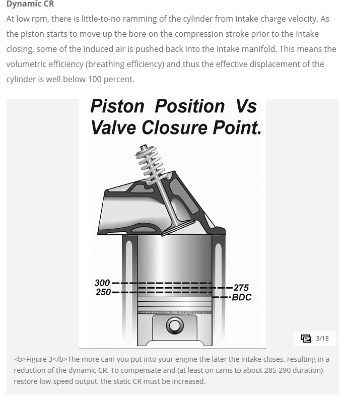
the 10.6:1 compression results in calcs that show that the intake valve should seat at about 70- 73 degrees past bdc and intake duration should be in the 240-245 range with exhaust duration maybe 5-7 degrees longer and a 105-106 lca, this is very likely to limit lift to the low to mid .580-.600 range in a hydraulic roller cam, if your want to maintain, a reasonably long and trouble free use as daily transportation.
IF you wanted to use the cams listed in the link boosting the compression too between 11.5:1-to 12:1 and use of race octane fuel would be required, to allow the full potential.
a 496 bbc will generally use a port cross sectional area near 4 sq inches.
this will place you in the larger oval port and smaller rectangle port standard bbc head configuration range.
when you see guys selecting long duration cams in a 496 BBC with only 10.7:1 compression thats intended to be used with pump octane high test fuel, they are generally trying to compensate for poor flowing cylinder heads, adding duration allows more time for the ports to flow but results in a lower effective dynamic compression ratio.
what length connecting rod and what piston pin height are you using, building the 496 BBC?
yes Im assuming its a tall deck 10.2" block and a 4.25" stroke
a 4.25" stroke,6.8" rod and 1.270 pin height, for that 10.2 deck height block
6.8" rod divided by a 4.25" stroke=1.6 ratio
displacement = bore x bore x stroke x 8 x .7854
1/2 stroke + rod length+piston pin compression height,
should roughly equal block deck height ,
plus or minus a few thousandths,
minor adjustments in compression,
due to head gasket thickness and what the piston deck height is are common
http://garage.grumpysperformance.co...-about-your-potential-dream-bbc-combos.14607/
http://garage.grumpysperformance.co...od-rod-length-too-stroke-info.510/#post-10311
http://garage.grumpysperformance.co...onnecting-rod-rod-length-too-stroke-info.510/
http://garage.grumpysperformance.com/index.php?threads/measuring-rod-and-pin-heights.3760/#post-9968
http://garage.grumpysperformance.com/index.php?threads/bbc-related-links-and-useful-info.17140/
Id also point out that cam timing matched to the exhaust scavenging has a huge effect on potential intake flow rates
a good set of BBC heads with a 2.30 inch intake valve, header primary's 38" long with 2" pipes and 3.5" collectors about 20 inches long, can flow more than adequately for the 496 BBC that will rarely see over 6500 rpm in a street/strip engine combo.
keep in mind the cam timing must match the header design and displacement and dynamic compression, to fully allow the cams overlap period to match the intended power /rpm band and effective exhaust scavenging.
something rather similar to this cam used with 1.8:1 roller rockers would be my suggestion.
yes I'm well aware that 90% plus of the people reading this thread ,
won,t bother to read through the links and sub links,
but for the few who want the info they are
included
found this gasket over at summit..
using the correct head gasket too match the heads and cylinder heads your using on any big block chevy engine, is critical to prevent coolant loss, and maintain proper cooling
be aware that head bolts enter the block coolant passages,
so if you failed to dip the bolt threads in sealant when they were assembled,
through the heads coolant can seep up along the head bolts,
into the area under the valve cover
btw read this
both of these work great at sealing head bolt threads,IF you forgot to use thread sealant on the head bolt threads, why, not try to eliminate one potential area of concern,why not pull each head bolt one at a time and clean its threads dip the clean bolt in the can of sealant and re-install and re-tighten the individual bolt to the required torque, before removing the next bolt, I've done this in the past when guys failed too seal the bolt threads and its worked and there was no head gasket issues later, the only thing you have to loose by trying this is the cost of a can of thread sealant and an hour or two of your time, and of course you'll more than likely need to re-adjust valves as the rockers will need to be removed at some point in the process..
http://www.summitracing.com/parts/FE...2/?image=large
Brand Fel-Pro
Manufacturer's Part Number Q8180PT2
Part Type Head Gaskets
Product Line Fel-Pro Head Gaskets
Summit Racing Part Number FEL-8180PT-2
Bore (in) 4.370 in.
Bore (mm) 110.998mm
Gasket Material PermaTorqueMLS
Compressed Thickness (in) 0.039 in.
Compressed Volume (cc) 9.700cc
Lock Wire No
Quantity Sold individually.
FIRST GEN, SBC CLOYES ROLLER TIMING SET
https://www.summitracing.com/parts/clo-9-1100/overview/
MARK IV BBC CLOYES ROLLER TIMING SET 1965-90
https://www.summitracing.com/parts/clo-c-3024x/overview/
MARK VI BBC CLOYES ROLLER TIMING SET 1991-95
https://www.summitracing.com/parts/...-specific/engine-family/chevy-big-block-gen-v
According to summits apps page
The gasket your have fits
http://www.summitracing.com/parts/FP...ET&prefilter=1
Make CHEVROLET
Engine Type V8
Liter 6.5
CID 396
Engine Size 6.5L/396
Beginning Year 1966
Ending Year 1970
Engine Family Chevy big block Mark IV
Make CHEVROLET
Engine Type V8
Liter 6.6
CID 402
Engine Size 6.6L/402
Beginning Year 1970
Ending Year 1972
Engine Family Chevy big block Mark IV
Make CHEVROLET
Engine Type V8
Liter 7.4
CID 454
Engine Size 7.4L/454
Beginning Year 1970
Ending Year 1990
Engine Family Chevy big block Mark IV
read and pay attention to the linked info
http://www.superchevy.com/how-to/en...-big-block-casting-changes-through-the-years/
http://garage.grumpysperformance.com/index.php?threads/another-496bbc.5123/
it may be the result of a crack in the head or block or just an intake or head gasket leaking, issue, as stated change oil and filter ,
and if the problem returns you darn sure better track down the source before repairs get exponentially more expensive
some cracks won,t leak until the engine heat of the engine thats been running for awhile expands the metal.
if its not up too operating temp, theres no leak.
its not un-common for intake gaskets to leak coolant,
into the lifter gallery if they were not correctly installed or damaged, or intake manifolds to leak coolant,
if the coolant passages are corroded or improperly machined,
or too find coolant leaks if the wrong head gaskets were used.
Quote:
Coolant Routing Mk IV/Gen 5/Gen 6
There are two different ways that coolant can be routed through the engine: series flow and parallel flow. Both ways work just fine. There may be a slight preference for parallel flow, but it is not a big deal. Series flow has the water exiting the water pump, flowing through the block to the rear, it then transfers through the head gasket and into the cylinder head through two large passages on each cylinder bank at the rear of the block. The coolant then travels from the rear of the head, forward to the front of the head, into the intake manifold water passage and out past the thermostat and thermostat housing. The water cools the block first, then it cools the head. The coldest water (coming out of the water pump) is directly below the hottest water (having already picked up the heat of the block and the head) as the hot water transfers into the intake manifold. By contrast, parallel flow has the water exiting from the water pump into the block, where a portion "geysers" up into the head between the first and second cylinder, another portion "geysers" up to the head between the second and third cylinders, another portion geysers up to the head between the third and fourth cylinder, and the remainder transfers to the head at the rear of the block. The coolant temperature inside the engine is more even that way. The differences in coolant routing is having (or not having) the three additional coolant transfer holes in each block deck, and three matching holes in the head gasket. The heads have passages for either system, and are not different based on coolant flow.
Be aware that gaskets that DO have the three extra holes between the cylinders often have restricted coolant flow at the rear--instead of having two large coolant transfer holes at the rear, there is only one, and it's the smaller of the two holes that remains. This is important because if you use a parallel flow head gasket on a series flow block, you can have massive overheating and there's NOTHING that will cure the problem except to replace the head gaskets with ones that don't restrict flow at the rear of the block, or to drill the block decks to allow the coolant to flow into the head between the cylinders. Here's why they can overheat: A series-flow block doesn't have the openings between the cylinders, no coolant can flow up to the head there. The gasket may only have the single, smaller opening at the rear, so the amount of water that gets through that opening is greatly reduced from what the block designers intended. The result is that the coolant flow through the engine is only a fraction of what is needed.
Most, but NOT all Mk IV engines are Series Flow. ALL Gen 5 and Gen 6 engines are Parallel Flow. A series flow block can be converted to parallel flow by drilling 3 holes in each deck surface, and then use parallel flow head gaskets. You can use the parallel flow gaskets as templates for locating the additional holes. It's really easy: Put the parallel flow gaskets on the block, mark the location and size of the three extra holes. Remove the gasket. Grab a 1/2" drill and a drill bit of the correct size, and pop the extra holes in the block. There is NO modification needed on the head castings. Some blocks have one of the holes already, but it needs to be ground oblong to properly match the gasket. Again, very easy with a hand held die grinder and rotary file.
I'd assume the intake gaskets are the source until proven otherwise.
but be aware that miss matched head gaskets, to the heads and block combo in use, can cause several issues
don,t assume the worst, just logically and step by step track down and correct the issue using FACTS.
The Gen V was first installed in the 1991 year models.
The earliest casting I've decoded was a very late (Nov/Dec?) 1989 date.
The Gen VI was first installed in the 1996 year models.
The cams for the Mark IV and Gen V are interchangable for flat tappet lifters.
The Gen VI where the first equiped with Roller Lifters, but the main difference is the machined flats on the lifter bores of this block - you can still install an earlier cam without rollers.
The cam retainer plate holes are verticle on a Gen V~VI, rotated 90deg from the Mark IV's horizontal orientation.
The '91 on trucks with Gen V's had manual transmissions and use a bracket for the pivot, the later medium duty trucks have a hydraulic clutch.
The Gen blocks use longer main cap bolts than the Mark blocks.
The crank on the Gen engines uses one long key in the keyway slot for the cam drive gear and the damper - the Mark cranks have two short keyway slots and two seperate keys, one for the cam gear one for the damper.
As he stated, Gen cranks are one-piece seal, Mark are two-piece.
The Flex plates are interchangeable - but Flywheels, for truck and marine applications, are not interchangeable on Mark and Gen engines.
KEEP IN MIND, MANY PEOPLE THAT HAVE BROKEN ROCKER STUDS HAVE FAILED TO VERIFY THE PISTON TO VALVE, CLEARANCES, ROCKER STUD TO ROCKER SLOT CLEARANCES,AND SPRING BIND CLEARANCES, etc.
it takes hundreds of pounds of force to bust rocker studs and or bend push rods, if you have those issues STOP AND LOCATE the geometry or CLEARANCE ISSUES CAUSING THE PROBLEM
theres several manufacturers and models available , heres a basic 1.5:1 ratio SBC version.
http://www.summitracing.com/parts/lun-85025
the grooved rocker pivot ball design was an effort by G.M. engineering to economically solve the issue of marginal oil flow causing rocker ball galling, and resulting noisy, or broken valve trains
FAILING TO READ THE LINKS WOULD BE A BIG MISTAKE HERE!
http://www.chevydiy.com/gaskets-fasteners-guide-big-block-chevy-engines/
http://www.superchevy.com/how-to/4567-chevrolet-big-block-engine-generations/
http://hotrodenginetech.com/top-10-reasons-to-build-gen-vi-based-big-blocks/
http://garage.grumpysperformance.co...-brief-big-block-chevy-history.951/#post-5878
http://garage.grumpysperformance.com/index.php?threads/another-496bbc.5123/
HEADS LIKE THIS WOULD BE A DAMN GOOD MATCH
http://www.airflowresearch.com/305cc-bbc-rectangle-port-cylinder-head/#specs (best)
http://www.jegs.com/i/Brodix/158/2061015/10002/-1 (ok)
https://www.summitracing.com/parts/nal-12363400/overview/ (OK)
https://www.summitracing.com/parts/tfs-41410001-m22/media/chartsandguides
http://www.compcams.com/Company/CC/cam-specs/Details.aspx?csid=584&sb=2
IF you have the newer mark V-or- VI ,1 piece rear seal block,
a forged scat rotating assembly similar too this, with the correct pistons, rings etc. might be used
https://www.summitracing.com/parts/sca-1-42460bi/applications
http://garage.grumpysperformance.com/index.php?threads/dynamic-vs-static-compression.727/
http://www.wallaceracing.com/runnertorquecalc.php
http://garage.grumpysperformance.com/index.php?threads/port-speeds-and-area.333/
http://garage.grumpysperformance.com/index.php?threads/crowers-valve-timing-charts.4299/
http://garage.grumpysperformance.com/index.php?threads/semi-fool-proof-cam-sellection.82/
http://www.wallaceracing.com/header_length.php
http://www.hotrod.com/articles/big-block-chevy-intake-cylinder-head-dyno-test/
http://www.superchevy.com/how-to/project-cars/sucp-1001-complete-chevy-big-block-build-testing/
http://www.chevydiy.com/how-to-build-chevy-big-blocks-intake-manifold-guide/
https://www.profilerperformance.com/206J-bbc-single-plane-intake.html
http://garage.grumpysperformance.com/index.php?threads/is-backpressure-hurting-your-combo.495/
http://garage.grumpysperformance.co...gine-to-match-the-cam-specs.11764/#post-55651
http://garage.grumpysperformance.co...y-in-building-a-good-engine.11682/#post-54682
http://garage.grumpysperformance.com/index.php?threads/port-speeds-and-area.333/#post-51660
http://garage.grumpysperformance.co...-calculators-and-basic-math.10705/#post-50173
ID call holleys tech guys for the correct 950cfm-1050 cfm dominator carb
https://www.holley.com/products/fuel_systems/carburetors/dominator/
(Words and photos by Scott Liggett) – We know many Bang Shifters are not made out of money. We are in that crowd ourselves. Any way we can save money on our project cars allows us to have a better car or truck. The easiest place to save money using our time and sweat instead of paying shop labor rates. One place many people often over look is the assembly part of rebuilding an engine.
Sure, there are few that have access to the tools necessary to do machine work on our engines, but putting together an engine doesn’t require fancy tools. A good torque wrench is about the only fancy tool that we needed putting together a 454 we recently had machined for a rebuild. Since we were getting estimates up to $500 from machine shops to assemble our engine, we decided that we save that money by taking the time to do it ourselves. That is just putting the new parts and machined block, crank and rods back together.
Yes, we were a bit apprehensive to do it. Engines are not cheap to get built these days. That can scare many people away from attempting this kind of work. But, after talking to some friends and our machine shops, we decided to go for it.
Truth be told, this is our second time assembling this 454 after machine work. But, the reasoning for this had nothing to do with the machine work done, or assembly job. We had two things that had us pulling the engine again after only 10,000 miles. First, we had constant lifter noise after the engine warmed up. Second,was piston slap from only doing a dingle ball hone with the original pistons with new rings and bearings. All the lifters failed a bleed down test and the pistons had too much clearance after the home honing job. This time we bought new pistons and had the block completely machined top to bottom with a .030 over bore. The rotating assembly had to be balanced for use with the new pistons.
You want to work in as clean as space as possible to avoid debris getting into your fresh engine. We were working in Scott’s one car garage at his house, which is pretty clean. We kept the engine covered by old, but clean towels in between days we were working on the engine.


This is how we received our 454 block back from the machine shop. The guys over at BluePrint Engines did the work for Scott and the block came back looking like a brand new casting, not like a 45 year old block. In case it isn’t obvious, the first thing to do is to get it on an engine stand. We got our from Harbor Freight, but this one is the big dog. A fully dressed 454 weighs near 700 lbs. They also replaced all the freeze and galley plugs for us.

After taping off the areas we didn’t want painted, we shot the engine in Chevy Orange. We were told not to paint in the oil filter housing, so we took some time to clean that up later in the build.

Before doing any assembly, we decided to see if our factory windage tray would work with the Milodon 7 quart oil pan and Melling high volume oil pump we are using. We also decided to upgrade to ARP main studs instead reusing the original main bolts for better support for the crank. The studs have provisions for the windage tray.
Even though the Milodon pan has these dimples to make room for the studs, we had to dimple them a bit more so the pan would sit flush on the block.

BluePrint Engines did the crank turning and balancing for us as well. The crank was standard when we took it to them, but polishing did not get all the scratches out of the bearing surfaces, so we had it turned .010/.010. They balance all their rotating assemblies below 2 grams, but ours came out .41 grams on the front and .89 grams on the back. We first laid in the block sides of the main bearings and carefully laid the crank in the block without any assembly lube at this point. Forged big block cranks weigh in excess of 60 pounds, so if you can get help to set it in the block, do so. Dropping it on your bearings, or your foot, would not be good.

Next, we cleaned the main caps with Brakleen and a lint free rag before installing their half of the main bearings. Even though the block was thoroughly washed after machining, their was still some dirt after sitting around for two weeks before getting to work on it. The rear main seal is not needed at this point.

We got some Plastigauge from the local parts store to double check bearing clearances. Your machine shop should have done this during the machining process with their measurements. You are just making sure. Taking your time and being anal during engine assembly is a good thing. After laying the piece of waxy, plastic string across the bearing surface on the mains, you place the main caps on and torque them down to manufacture specs. In the case of our 454, it was 105 ft lbs.


Next, remove the main caps and check the measurements on the Plastigauge’s paper cover. Our Chevy Factory Overhaul Manual says that the main should have between .001 and .003 clearance. All of our mains had .015 readings. This is only approximately, but you are being sure of what you got before you have the engine together and running. The alternative is finding bearing material in your oil filter after a few miles. Not a good day. Repeat this process on all of the main caps and bearings.
Remove the crank from the block, then get out your engine assembly lube and liberally cover the main bearings. Then, you need get out the rear main seal from your engine gasket set. Fel-Pro includes instructions on which way it is suppose be installed to keep it from leaking all over your driveway.

Some people say you should install the rear main seal halves offset slightly for better leak protection. Others don’t. We did.. We did add a little bit of RightStuff sealant on the seal ends for added security.

Now your crank is done. Time to move on the connecting rods and pistons. We used the same plastigauge on each of the rod bearings to check their clearances as well.
For the purpose of checking the bearing clearances with the pistons already installed on the rods, we did this before installing the rings on the pistons. This made sliding them in and out of the bores much easier. The rods were stamped with their numbers when Scott took the engine apart before machining, but he wrote big numbers on the end caps cause he is slowly going blind like all middle aged men. The machine shop added those colored paint dabs as part of their checks and rechecks. They mark the side of the rod that has the rod bearing tabs. The tabs should face towards the outer part of the block.

Torque the rod bolts to their recommended specs. Before removing the rod caps and checking the clearances with the plastigauge you used, check the side clearances on the rods. We checked between the rod pairs and between the rods and the crank sides. On our 454, those clearances should be between .015″ and .021″. Bearing clearances on our 454 is the same as mains, .001″-.003″.
After checking the rod clearances were all good, we moved on to installing the rings on the pistons. Even if you buy rings that are supposed to be pregapped, we suggest you check the clearances anyways. Remember what we said about being thoroughly anal? Our rings came with our piston set from Keith Black. They are moly rings, but we had to gap them. It is tedious, but necessary. Too tight of clearances and you will break them and the ring lands on the pistons. Too loose and you can have oil usage problems and lack of power. We wanted to get consistent measurements, so we always made sure they were the same distance down in the bores each time.

Using a feeler gauge find the clearance on the ring. The measurement will depend on the type of rings you are using and the intended purpose of your engine. The use of nitrous and boosted engines need more clearance for the added cylinder pressure and heat. We wanted .021″ on the top ring, and .024″ on the second ring.

Our rings needed a bit of filing. here are ring gapping tools available from many companies, but we put a metal file in the bench vise and gently ground them a bit. Do a little bit at a time. Don’t get in a hurry. It’s better to go back to the file a few times, then over gap your rings.

Once all 16 rings are gapped, they need to be installed on the pistons. Certain types of rings are reversible. Ones that are not often have a dot to which side is the top. Keith Black’s instructions said not spiral them onto the pistons. This means we needed to spread the two ends apart in order to get the rings on the pistons. There are many inexpensive tools for safely doing this. We should have gotten one ourselves as we got impatient and broke one of the rings trying to install it. The oil rings are the easiest to install and are usually three pieces.


Since ring sets don’t come with spares, we had to order another set. We were able to get another set of the same style and material from another brand, but it will work.

Clock the rings 180* apart before moving on to installing the pistons and rods in the engine for the last time.
Now that there are piston rings on your pistons, getting them into the block is a little more work. So not damage the bearing surfaces on your crank, cover the rod bolts with rubber hoses or specific boots so not to scratch crank. We just used 3/8″ fuel line.

Now, it’s time to install your rods and pistons for the last time. You will need a ring compressor. There are fancy, size specific ones available. We just used this $18.00 one we got at Napa. Set the rod into the bore, then tap the compressor flush with the deck surface of the block. Be sure the valve reliefs in the pistons are oriented in the correct direction.

We used the rubber handle of a ballpeen hammer to tap the piston down into the bore. A dead blow, or a specific dead blow piston driving tool will work as well. Just do not use anything metal against the piston face. That would be bad.
With this type of ring compressor tool, you do need to stop a couple of times during the piston installation to be sure the compressor stays flush with the deck surface. If the piston ring slips out, you will be starting over.

Use the engine assembly lube on the rod bearing halves just like the main bearings. When you get the piston driven down to where the rod meets the crank throw, put the rod cap on the rod and tighten the bolts down to recommended specs. Our ARP rod bolts were torqued to 50 ft lbs.

You will need to install your oil pump next. Don’t forget the oil pump pickup screen as well. We are using a Melling high volume pump and a pickup screen for use with a 7 quart oil pan. This pickup screen is pretty much dummy proof in it’s installation. We still checked for it’s clearance to the bottom of the oil pan. Before installing the oil pump, make sure you install the oil pump drive shaft first, or the day you fire up your engine will not be a good day. The oil pump’s bolt gets torqued to 60 ft lbs on our 454. The rotating assembly installation is complete.


We took some extra time to install our factory windage tray for better oil control and a few more horsepower. Our ARP stud kit included the four longer studs for its use. Be sure to check the rod clearance under the windage tray. Rotating parts need at least .060″ clearance.


Flip the engine back over for the camshaft installation. Apply liberal amounts of moly lube to the camshaft lobes and bearing surfaces. We only add the moly lube to four lobes and a bearing surface at a time, then install the cam up to that point. Then add some more to the next set of four. The keeps your hands cleaner and it easier to install. We used a 5/16″ x 6 inch long bolt in the front of the cam for more leverage. Or, you can buy a cam handle. We’re cheap.
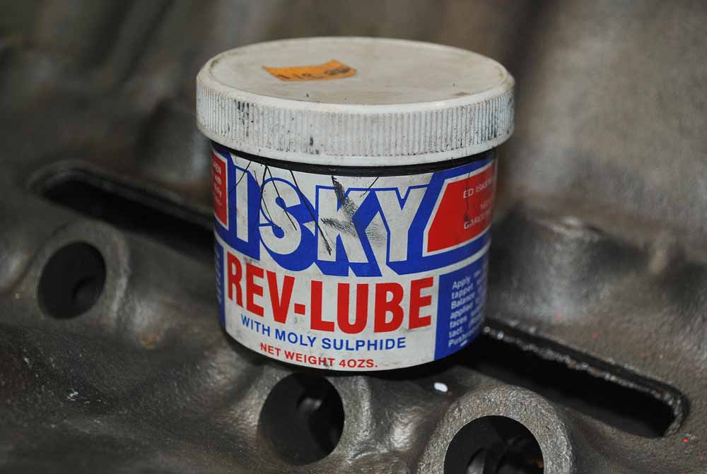
We used this cam moly lube we got from Isky. This tub has been used on five or six cams and we still have plenty left.


The last thing to do is install the timing chain. First, drive the crank gear on the crank with the round dot on the crank key way and the dot pointing straight up. The cam gear goes on with the dot pointing straight down. This Cloyes timing set has a three way set up for advancing, or retarding the cam 4*. We installed ours straight up.
That’s it for the short block. The cam’s lifters will go in with the pushrods and valvetrain. It wasn’t all that hard, was it? We did this over a weekend.
http://www.hotrod.com/how-to/engine/0806phr-chevy-496-big-block-engine-build/
http://www.dragzine.com/news/probe-industries-496ci-pistonsstroker-kits-for-big-blocks/
http://idealhowtovideo.com/bigblock80006.htm
http://www.superchevy.com/how-to/project-cars/sucp-0312-496-street-bruiser/
http://www.twperformanceparts.com/index.php?route=product/product&product_id=5302
http://www.twperformanceparts.com/index.php?route=product/product&product_id=3910
http://www.superchevy.com/how-to/project-cars/sucp-0901-496-chevy-big-block-build/
http://www.superchevy.com/how-to/engines-drivetrain/1407-642-hp-budget-iron-head-build/
http://garage.grumpysperformance.co...-articles-you-might-want-too-look-over.14682/
http://garage.grumpysperformance.com/index.php?threads/build-a-496-stroker-bbc.101/
http://www.superchevy.com/how-to/engines-drivetrain/1005chp-496ci-engine-build/
http://www.ebay.com/itm/Step-by-Ste...Big-Block-Engine-2-Disc-5Hr-DVD-/370654732889
http://garage.grumpysperformance.co...im-good-to-go-on-valve-clearance-right.15160/
http://www.superchevy.com/how-to/en...estech-performance-496-chevy-big-block-build/
http://www.hotrod.com/how-to/engine/116-0703-big-block-chevy-engine-build/
like with most performance parts and applications the critical part of the build,
is generally in selecting the correct components for that particular application,
and in assembling those components correctly with the correct clearances.
its always a multi layered process,
you can,t expect sub-par or weak parts to withstand the shock and torque and rpm/impact loads.
you can,t also expect improperly installed or clearanced or insufficiently lubricated or cooled parts to last very long under loads.
obviously the process REQUIRES the person doing the work, or assembly to do some in depth research,
and have any tools or measuring devices that will be needed.
- I think most of us have run into a great many similar choices, between buying tools and auto parts,
its simply the result of a limited budget ,in most cases,
and most of us make a few mistakes ,
but as long as you keep the goal of building the car in mind you'll do ok.
after you gain experience there's both engineering and art involved in the process,
you'll generally start with a goal, you've envisioned for your car, reality and physics will provide some of the limitations, you'll be limited to a budget and at times by your access too tools and limited by your skills and knowledge, youll generally start,by simply making a very detailed list of the components you want too use ,to upgrade and modify the car to gain the performance and look of the car, and once you have that list of components, and being forced by going back through that detailed, list and doing the required math too verify you have selected the correct matching parts, and when you find you have to change a few components you go back, change the list and again revue the math, most of us start out without the required knowledge to accurately match parts and your goal.
yet this process forces you to do some research into what you can reasonably accomplish with the tools and skills you have and the realization that you may need to acquire both skills and more tools as you proceed.
the sub links contain a wealth of info
http://garage.grumpysperformance.com/index.php?threads/a-few-basic-precision-tools.16344/
http://garage.grumpysperformance.co...tion-of-crank-durring-short-blk-assembly.852/
http://garage.grumpysperformance.com/index.php?threads/bearing-clearances.2726/
http://garage.grumpysperformance.co...d-rod-orientation-clearance-issues-etc.16027/
http://garage.grumpysperformance.co...ng-rod-bolt-stretch-preload.11050/#post-85102
http://garage.grumpysperformance.com/index.php?threads/another-496bbc.5123/
http://garage.grumpysperformance.co...-building-a-peanut-port-big-block-combo.2900/
http://garage.grumpysperformance.com/index.php?threads/bbc-build-advice.15921/
http://garage.grumpysperformance.co...e-springs-and-setting-up-the-valve-train.181/
http://garage.grumpysperformance.co...-on-the-cheap-well-to-start.11739/#post-55478
http://garage.grumpysperformance.co...y-in-building-a-good-engine.11682/#post-54682
http://garage.grumpysperformance.com/index.php?threads/bearings-and-oil-flow.150/
http://garage.grumpysperformance.com/index.php?threads/oil-system-mods-that-help.2187/
Everything You Wanted to Know About the Big-Block Chevy Engine
The big block Chevy is one of the most raced engine platforms in motorsports. We've compiled some history and a massive library of parts swap knowledge into a comprehensive resource. Read on!
blog.dartheads.com
Various Chevy Big-Block Casting Changes
We show you the latest Chevrolet big-block casting and how it differs from earlier versions. Tale a look at the changes here!
Differences In Gen IV, V, and VI Big Blocks | Ground Up Motors - SS396.com
What exactly are the differences between the generations of big blocks? The big block Chevy engine, AKA BBC, AKA Rat Motor, has been in production since 1965.
www.ss396.com
Generation Gap: Big-Block Chevy OE And Aftermarket Block Variants
The big-block Chevy has been around for 60 years and is still going strong. We look at the major generations within the BBC lineup.
Last edited: