http://store.summitracing.com/partdetai ... toview=sku
https://www.carshopinc.com/product_info.php/products_id/49347/SPG1-12
yes I use both micrometers and snap gauges and cross check with plasti-gauge
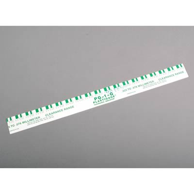
and yes when you compare the crushed width of the plasti-gauge youll find it rarely falls as an exact match to the bar chart tape that is packaged with it so you can judge clearance based on crush width
http://garage.grumpysperformance.com/index.php?threads/bearing-clearances.2726/
btw spray the bearing and the crank surfaces, and the plastigage with WD40 before you measure clearances and it won,t tend to stick as much

http://www.compperformancegroupstores.c ... re_Code=PH
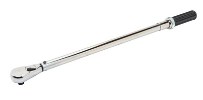
viewtopic.php?f=50&t=342&p=418&hilit=+wrench#p418
http://video.google.com/videosearch?oe= ... Q&start=20
http://www.carcraft.com/techfaq/116_070 ... index.html
[color=#ff00000]you can buy single strips but its far cheaper in larger size boxes, if your useing it frequently[/color]
http://store.summitracing.com/partdetai ... toview=sku
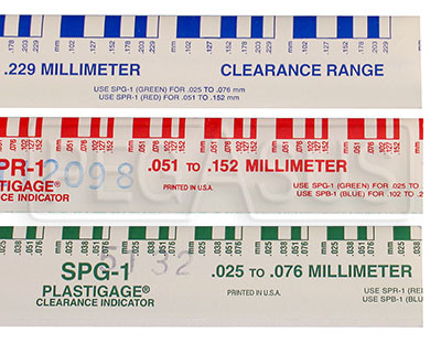
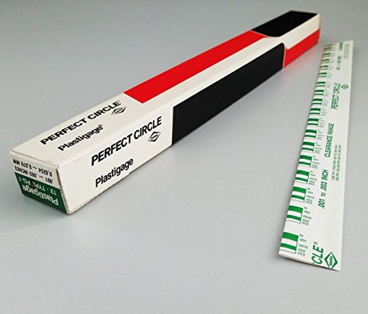
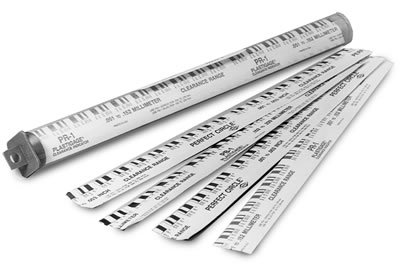
Plastigage, Green Kit, 0.001 in.-0.003 in. Clearance Range, Each
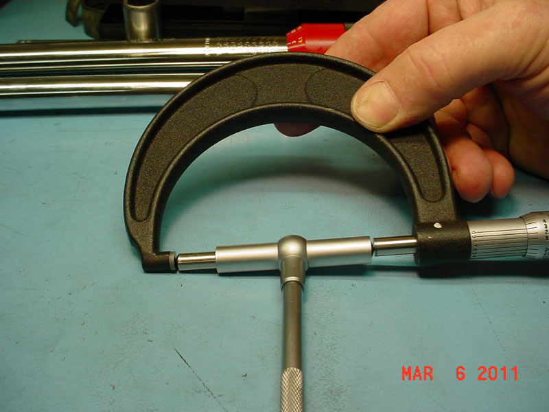
Ive always used both the .002-.006 range AND the 0.001 in.-0.003 in. Clearance Range, plus a complete set of mics and snap gauges
with no problems
"Accurately measure bearing clearances.
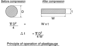
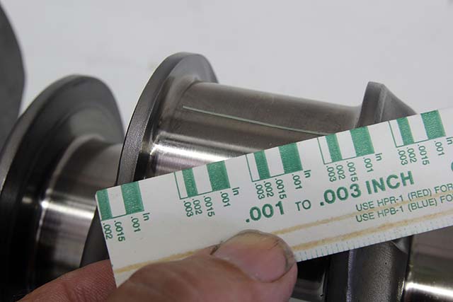
Made from a special extruded plastic thread with accurately controlled crush properties, Plastigage provides a fast and accurate way to check bearing clearances. Plastigage is packaged in a calibrated envelope that not only protects the plastic threads, but also serves as a scale to measure the bearing clearance. One package contains enough Plastigage to check both main and connecting rod clearance for one engine. "
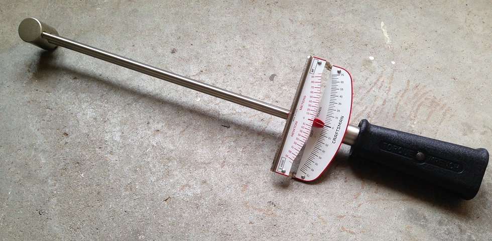
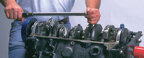
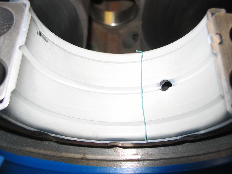
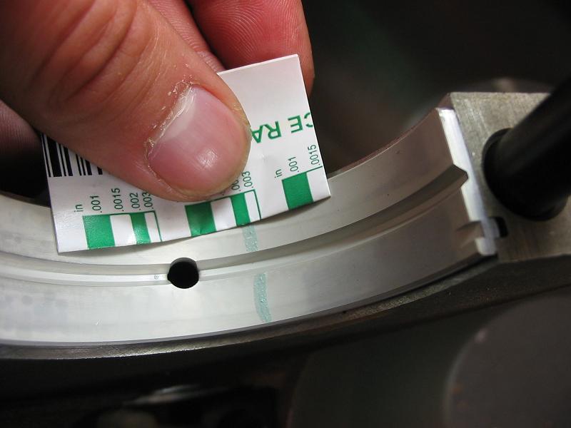
now this stuff is really easy to use , it looks like green angle hair spaugetti,, you spray down your crank journal,and matched bearing surfaces with wd-40 so it won,t stick to the surfaces, lay a 1/2" long section in the center of the journal, replace the bearing cap, and torque to specs, then WITHOUT spinning the crank you disassemble the bearing cap, remove the cap and use the edge of the package the plastigage came in to compare the crushed width to the scale on the edge of the packaging.
simple and REASONABLY EFFECTIVE, if you don,t own snap gauges and a full set of mics.......just remember to remove it from the bearing or journal,before you proceed further, in the engines reassembly
now personally I like the stuff (PLASTIGAGE) as a secondary way to check bearing clearances, but a decent set of mics and a machinists caliper and snap gauges is a good thing to have , and altho I use plastigage I don,t trust it alone to check clearances

http://www.harborfreight.com/cpi/ctaf/d ... umber=5649

http://www.harborfreight.com/cpi/ctaf/d ... mber=32214

http://www.harborfreight.com/cpi/ctaf/d ... umber=5043

http://www.harborfreight.com/cpi/ctaf/d ... mber=97389
http://www.use-enco.com/CGI/INPAGE?PMPA ... s/317-0764
now theres FAR better QUALITY tools than the ones I linked too, but unless your doing engines on a regular basis I find these will work reasonably well, naturally if your doing it seriously youll want better quality tools
HERES MORE INFO
Plastigage, a registered trade mark, is used to determine the clearance between a bearing insert and its journal. For the occasional engine builder, using this product is a much cheaper alternative to purchasing sets of OD and ID micrometers, which will easily run into a thousand dollars or more.
The proper way a machinist would determine bearing clearance would be to measure the OD of the journal diameter of a shaft and subtract from that the ID of the installed bearing insert, the difference being the clearance.
The clearance provides space for several events, first shafts and blocks are seldom if ever exactly straight so the clearance provides mechanical space where the shaft can find the center between it and the block. The clearance is then taken up by the oil pumped into the clearance such that the shaft is supported on a wedge of oil all the way around the journal. The clearance also provides a leakage rate for the oil thru the bearing to remove heat and debris, and keeps lubrication on the bearing surfaces which would be worked out by the mechanical forces if these were lubed with grease.
If the clearance is too tight, the shaft and block cannot find a center that provides an oil wedge all around the bearing, then there will be metal to metal contact. This problem is made worse by expansion of parts when they heat up and expand into the clearance. If the clearance is too wide an oil wedge cannot form because the leakage rate out of the bearing is too high, again metal to metal contact will occur.
The factory and bearing manufacturers specify a range of acceptable clearances for your engine. Running on the lower side is good for commuter street use as it minimizes oil loss thru the bearing which reduces the work the oil rings have to do in-order to keep excessive oil thrown from the crank off the cylinder walls. It also allows the factory to run a smaller hence cheaper oil pump, this also reduces parasitic power losses from the crankshaft which improves fuel mileage on their government mandated CAFE tests. Performance use dictates that clearances be set toward the high side to allow for greater thermal expansion that comes with the heat of competition. These wider clearances are usually accompanied with a high volume oil pump to insure enough oil is pumped thru the engine to provide wedge development inside the bearings. This always results in tremendous amounts of oil being slung off the crankshaft which if left uncontrolled will overcome the oil rings ability to scrape it off the cylinder walls. To control this oil, competition engines will include scrapers and windage trays to peel this extra oil off the crank and return it to the pan.
Clearance between the crank's rod journal and bearing, while lacking the long alignment issue of the main journals to block, are subject to many of the same problems in developing an oil wedge between the journal and the bearing insert. There are additional problems with the rods in that there are alternating loads between power stroke and the other strokes that the oil wedge must protect the journal and bearing from. This is made more difficult by the fact the bearings are rather narrow making it easy for the forces on the power stroke to blow the wedge out. Plus these bearings carry the greatest loads which always hit in exactly the same place, so impact and heat are big problems for these bearings requiring a lot of oil flow thru them to cool the working surfaces. Again the manufacturer specifies clearances and the same rules apply here as with the main bearings regarding street to competition use.
The choice of bearing material also affects what clearances should be used. Typically copper/lead, copper/tin, copper/babbitt bearings should run toward the low side to the middle of clearances, aluminum bearings should be set from the middle to upper band of the clearances.
If you're building a full out race motor you can run wider clearances than recommended, but this is the ozone of pros who usually can afford to replace the motor if their clearance choices are wrong. Don't go there unless you've got big bucks and intend to run with the big boys.
Plastigage comes in several size ranges, so you need an idea of where your clearances should be falling in-order to get the right stuff. If the clearances are wrong the only choice is machining. Too tight and the shaft may have to have one or more journals turned down. If the clearance is too wide then either the shaft has to be replaced or it can be turned to a standard undersized with new specific bearings for that undersize. If the shaft is a little too large or small, most bearing companies and the factory include a selection of bearings that range from +/- .0001 to .00015 or .0002 inch around the nominal dimension so you can dial the clearance in pretty well.
Bogie posted this info above
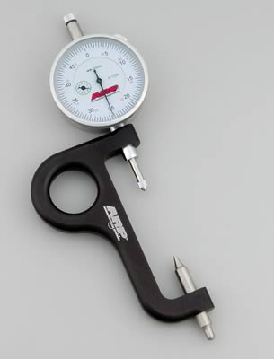
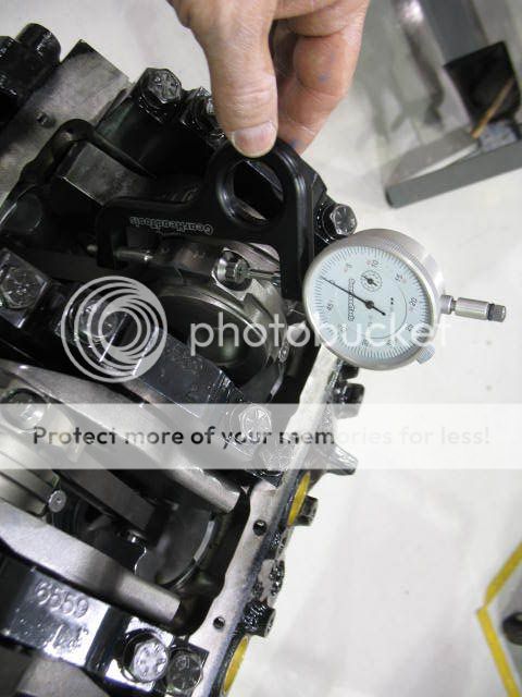
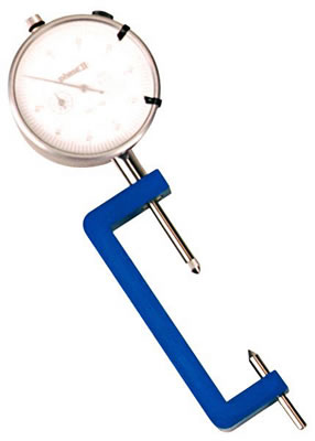
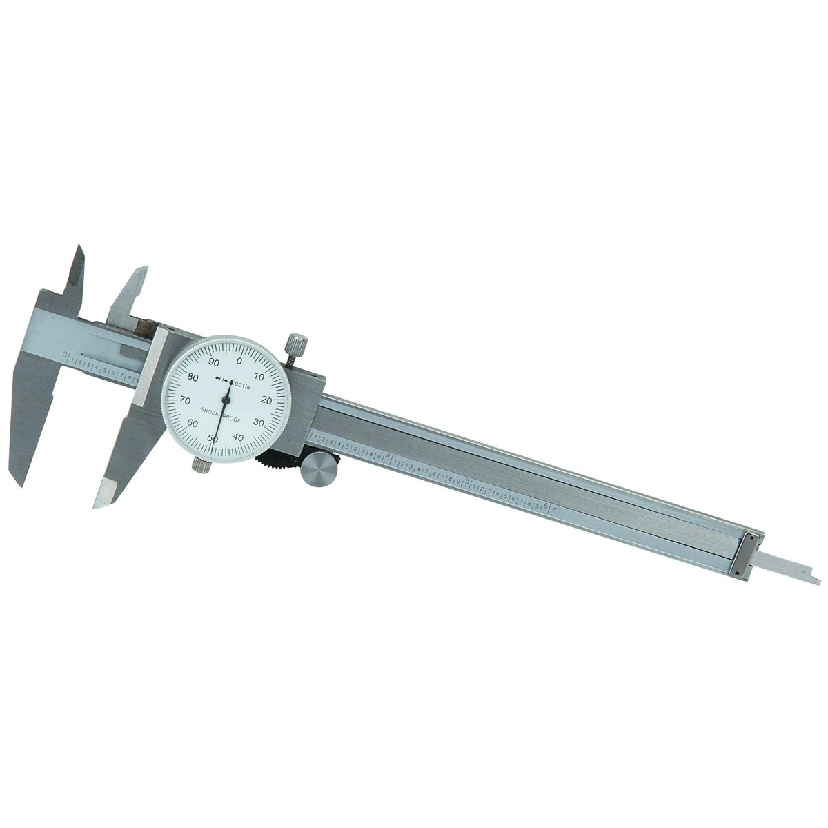
yes I find it amazing that theres guys in this hobby without snap gauges and dial indicator calipers, so many problems are avoided by actually knowing the accurate measurements
http://www.harborfreight.com/6-inch-dia ... 66541.html
https://www.carshopinc.com/product_info.php/products_id/49347/SPG1-12
yes I use both micrometers and snap gauges and cross check with plasti-gauge
and yes when you compare the crushed width of the plasti-gauge youll find it rarely falls as an exact match to the bar chart tape that is packaged with it so you can judge clearance based on crush width
http://garage.grumpysperformance.com/index.php?threads/bearing-clearances.2726/
btw spray the bearing and the crank surfaces, and the plastigage with WD40 before you measure clearances and it won,t tend to stick as much
http://www.compperformancegroupstores.c ... re_Code=PH
viewtopic.php?f=50&t=342&p=418&hilit=+wrench#p418
http://video.google.com/videosearch?oe= ... Q&start=20
http://www.carcraft.com/techfaq/116_070 ... index.html
[color=#ff00000]you can buy single strips but its far cheaper in larger size boxes, if your useing it frequently[/color]
http://store.summitracing.com/partdetai ... toview=sku
Plastigage, Green Kit, 0.001 in.-0.003 in. Clearance Range, Each
Ive always used both the .002-.006 range AND the 0.001 in.-0.003 in. Clearance Range, plus a complete set of mics and snap gauges
with no problems
"Accurately measure bearing clearances.
Made from a special extruded plastic thread with accurately controlled crush properties, Plastigage provides a fast and accurate way to check bearing clearances. Plastigage is packaged in a calibrated envelope that not only protects the plastic threads, but also serves as a scale to measure the bearing clearance. One package contains enough Plastigage to check both main and connecting rod clearance for one engine. "
now this stuff is really easy to use , it looks like green angle hair spaugetti,, you spray down your crank journal,and matched bearing surfaces with wd-40 so it won,t stick to the surfaces, lay a 1/2" long section in the center of the journal, replace the bearing cap, and torque to specs, then WITHOUT spinning the crank you disassemble the bearing cap, remove the cap and use the edge of the package the plastigage came in to compare the crushed width to the scale on the edge of the packaging.
simple and REASONABLY EFFECTIVE, if you don,t own snap gauges and a full set of mics.......just remember to remove it from the bearing or journal,before you proceed further, in the engines reassembly
now personally I like the stuff (PLASTIGAGE) as a secondary way to check bearing clearances, but a decent set of mics and a machinists caliper and snap gauges is a good thing to have , and altho I use plastigage I don,t trust it alone to check clearances
http://www.harborfreight.com/cpi/ctaf/d ... umber=5649
http://www.harborfreight.com/cpi/ctaf/d ... mber=32214
http://www.harborfreight.com/cpi/ctaf/d ... umber=5043
http://www.harborfreight.com/cpi/ctaf/d ... mber=97389
http://www.use-enco.com/CGI/INPAGE?PMPA ... s/317-0764
now theres FAR better QUALITY tools than the ones I linked too, but unless your doing engines on a regular basis I find these will work reasonably well, naturally if your doing it seriously youll want better quality tools
HERES MORE INFO
Plastigage, a registered trade mark, is used to determine the clearance between a bearing insert and its journal. For the occasional engine builder, using this product is a much cheaper alternative to purchasing sets of OD and ID micrometers, which will easily run into a thousand dollars or more.
The proper way a machinist would determine bearing clearance would be to measure the OD of the journal diameter of a shaft and subtract from that the ID of the installed bearing insert, the difference being the clearance.
The clearance provides space for several events, first shafts and blocks are seldom if ever exactly straight so the clearance provides mechanical space where the shaft can find the center between it and the block. The clearance is then taken up by the oil pumped into the clearance such that the shaft is supported on a wedge of oil all the way around the journal. The clearance also provides a leakage rate for the oil thru the bearing to remove heat and debris, and keeps lubrication on the bearing surfaces which would be worked out by the mechanical forces if these were lubed with grease.
If the clearance is too tight, the shaft and block cannot find a center that provides an oil wedge all around the bearing, then there will be metal to metal contact. This problem is made worse by expansion of parts when they heat up and expand into the clearance. If the clearance is too wide an oil wedge cannot form because the leakage rate out of the bearing is too high, again metal to metal contact will occur.
The factory and bearing manufacturers specify a range of acceptable clearances for your engine. Running on the lower side is good for commuter street use as it minimizes oil loss thru the bearing which reduces the work the oil rings have to do in-order to keep excessive oil thrown from the crank off the cylinder walls. It also allows the factory to run a smaller hence cheaper oil pump, this also reduces parasitic power losses from the crankshaft which improves fuel mileage on their government mandated CAFE tests. Performance use dictates that clearances be set toward the high side to allow for greater thermal expansion that comes with the heat of competition. These wider clearances are usually accompanied with a high volume oil pump to insure enough oil is pumped thru the engine to provide wedge development inside the bearings. This always results in tremendous amounts of oil being slung off the crankshaft which if left uncontrolled will overcome the oil rings ability to scrape it off the cylinder walls. To control this oil, competition engines will include scrapers and windage trays to peel this extra oil off the crank and return it to the pan.
Clearance between the crank's rod journal and bearing, while lacking the long alignment issue of the main journals to block, are subject to many of the same problems in developing an oil wedge between the journal and the bearing insert. There are additional problems with the rods in that there are alternating loads between power stroke and the other strokes that the oil wedge must protect the journal and bearing from. This is made more difficult by the fact the bearings are rather narrow making it easy for the forces on the power stroke to blow the wedge out. Plus these bearings carry the greatest loads which always hit in exactly the same place, so impact and heat are big problems for these bearings requiring a lot of oil flow thru them to cool the working surfaces. Again the manufacturer specifies clearances and the same rules apply here as with the main bearings regarding street to competition use.
The choice of bearing material also affects what clearances should be used. Typically copper/lead, copper/tin, copper/babbitt bearings should run toward the low side to the middle of clearances, aluminum bearings should be set from the middle to upper band of the clearances.
If you're building a full out race motor you can run wider clearances than recommended, but this is the ozone of pros who usually can afford to replace the motor if their clearance choices are wrong. Don't go there unless you've got big bucks and intend to run with the big boys.
Plastigage comes in several size ranges, so you need an idea of where your clearances should be falling in-order to get the right stuff. If the clearances are wrong the only choice is machining. Too tight and the shaft may have to have one or more journals turned down. If the clearance is too wide then either the shaft has to be replaced or it can be turned to a standard undersized with new specific bearings for that undersize. If the shaft is a little too large or small, most bearing companies and the factory include a selection of bearings that range from +/- .0001 to .00015 or .0002 inch around the nominal dimension so you can dial the clearance in pretty well.
Bogie posted this info above
yes I find it amazing that theres guys in this hobby without snap gauges and dial indicator calipers, so many problems are avoided by actually knowing the accurate measurements
http://www.harborfreight.com/6-inch-dia ... 66541.html
Last edited by a moderator: