The ratio between the caliper and master cylinder is a function of the net effective caliper piston bore area divided by the bore area of the master cylinder. To compare these ratios and do the calculation, you must start with the total piston area of the pistons in one side of one caliper.
Id also point out most disc brakes are designed to be used with a master cylinder thats using a matched power brake booster, and calipers as a set.
and that generally requires a certain minimal engine vacuum.
are you using a master cylinder and power brake booster,
that are original factory-matched to the brake calipers you installed?
what is the engine plenum vacuum at idle?
related threads
https://www.joesracing.com/master-cylinder-math/#:~:text=The ratio between the caliper,one side of one caliper.
http://garage.grumpysperformance.co...ouble-shooting-brakes-3.380/page-2#post-93670
http://garage.grumpysperformance.com/index.php?threads/c4-brakes-and-trouble-shooting-them.15862/
http://garage.grumpysperformance.com/index.php?threads/trouble-shooting-brakes-1.526/#post-6093
http://garage.grumpysperformance.com/index.php?threads/trouble-shooting-brakes-2.972/
http://auto.howstuffworks.com/auto-parts/brakes/brake-types/power-brake1.htm
http://auto.howstuffworks.com/auto-parts/brakes/brake-types/power-brake2.htm
http://auto.howstuffworks.com/auto-parts/brakes/brake-types/power-brake3.htm
BRAKES
Master Cylinder Math
Going faster creates a need for stopping faster. Efficient braking is based on choosing the right components and matching the proper combinations will result in a brake system that works in conjunction with the specifics of your car, track and driver style. It is highly recommended that you work with your brake company engineer to assist you in building the right combination to tailor a system for your application. Since pad compound, rotors, calipers and master cylinders all work together in relation to car weight, speed and track characteristics, it makes sense to think of your brake system as a package. Each brake component relates to the other braking variables and an individual change may necessitate the need to reanalyze your entire brake system in your effort to achieve a balanced clamping force on your car.
We contacted long time brake expert Carl Bush from Wilwood engineering to help our readers understand the brake system. While I encourage you to consult your brake company engineer to build the right braking system, I also encourage you to learn how the parts interrelate. With your own knowledge base, education will allow you to better communicate your needs resulting in the best brake system possible.
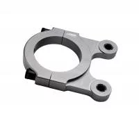
Billet Clamp on Reservoir Mount
A Billet Clamp On Reservoir Mount allows you to mount your brake fluid reservoir at a high point resulting in improved brake bleeding. Remote mounting keeps unwanted heat away from your brake fluid.
Question: How do you pick the proper master cylinder?
Carl Bush: Master cylinders are an integral component in the brake system. They are responsible for sending the correct amount of pressure and balance to the brake calipers. But it must be remembered that they are only one component in a system, and do not function alone. Brake requirements for different types of race cars will vary by component and element. But all systems do carry a common thread. They must allow the driver to stop the car with comfortable leg effort while contributing to the overall handling and performance of the car.
Question: How do master cylinders work?
Carl Bush: A master cylinder is used to convert force from the brake pedal into the hydraulic pressure that operates the brake calipers. The amount of pressure generated is a function of the force being applied, divided by the master cylinder bore area. A 1” master cylinder has a bore area of .785” inches squared. For every hundred pounds of force applied to the master cylinder piston by the pedal push-rod or balance bar, that master cylinder will generate pressure equal to 100 divided by .785 or 127.4 PSI. By calculating the area in inches squared (bore x bore x .785”) for any master cylinder size, you can calculate how much pressure change would be affected by a bore size change.
A 7/8” bore master cylinder has a bore area of .6” inches squared. If we apply that same 100 pounds of force to the 7/8” master cylinder, using the formula 100 divided by .6, that same 100 pounds of force from the pedal will generate 166.7 PSI. A decrease in master cylinder bore area produced a proportionate increase in line pressure. This line pressure management becomes a key factor in setting brake balance.
Master Cylinder bore size
Master Cylinder bore size is the element that affects pressure
Math Explained
Carl explains that a 1” Master Cylinder has a bore area of .785” squared. To get to this number you use the formula for Area which is: Area = 3.14 (Pi) multiplied by the radius squared. So you calculate the radius of 1” bore which is simply half of the diameter which equals .5” (half an inch). The result is that a 1” master cylinder has a radius of half an inch. You then multiply your radius which is a half an inch (.5) by itself so .5” X .5” = .25” or a quarter of an inch. .Multiply .25 X 3.14 (pi) and you arrive at Carl’s .785” area number. Basically, I just repeated what Carl said in an effort to make the math more simple and I bet the barrage of numbers made the calculation more intimidating and confusing? It’s ok – we will get to a simple way to look at the master cylinder math and going through the steps will make the process easier to understand.
Another way to explain Carl’s math uses a 7/8” master cylinder as the example. We will do the calculation and show our work to reinforce the math for calculating bore area.
Bore = 7/8”
7 divided by 8 gets us the decimal equivalent = .875”
The Radius is .875” divided by 2 = .4375”
.4375” Multiplied by .4375” (Squared) = .1914”
.1914” Multiplied by (Pi) 3.14” = .6” – which is the answer Carl explained above.
With the progression towards understanding the math we can do take the steps the easy way. Use Carl’s magic formula of Bore X Bore X .785” (.785 is the magic number that simplifies the above equations as it simply pre-calculates the squared business relating to Pi in advance). So a 7/8” bore is .875” X .875” X .785” = .6” Bore Area. It turns out you can use the number .785” and multiply it by ANY Bore X Bore as the reusable number of.785” is a derivative of Pi and it is a repeatable math number that can be used with any and all bore sizes. So, the complicated math shown relating to Master Cylinder Bore Area can be simplified. Now we have taken another step towards understanding.
Bore X Bore X .785” – you can always use .785” in the equation.
Let’s check with the Easy 1, 2, 3 method:
For an example 7/8” Bore master cylinder the Bore Area math is:
- Step 1 – Convert the fraction Bore to a decimal by dividing the bottom number in the fraction into the top number.
- 7 divided by 8 = .875”. 7/8” is the bore marked on the outside of the master cylinder and .875” is the decimal bore equivalent of 7/8”
- Step 2 – Multiply the bore diameter (our example is .875”) by itself which is the same as bore squared.
- Step 3 – Multiply the bore squared result from step 2 (.766) by the reusable number (always .785 with every master cylinder size – you can count on .785 to work every time with every master cylinder size).
- .875” X .875” = .766
- .766 X .785” = .6
- .6 is the Bore Area for a 7/8” Master Cylinder!
- The EASY 1, 2, 3 Bore Area calculation is right here!
Our example was for a 7/8” master cylinder. Now you can use the bore size on your car and substitute your actual numbers to come up with your Bore Area, front and rear, by following the 1,2,3 calculation above. Now that we have our Bore area numbers of .6 for a 7/8” master cylinder and .785” for a 1” master cylinder what do we do next? Carl states that a smaller master cylinder bore creates more pressure with an equal amount of force. A 1” master cylinder creates 127.4 PSI as compared to a 7/8” master cylinder which is 166.7 PSI based on your foot making 100 pounds of force at the master cylinder. It is important to consider that the smaller cylinder makes more pressure but the smaller bore will move less fluid. More travel will be needed to make up for the reduction in fluid moved by a 7/8” master cylinder as compared to the larger 1”. Carl explains further in the next section.
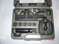
Caliper Mount
Utilizing a bolt on caliper mount ensures that your calipers are square to the rotor improving pad wear and braking efficiency.
How do fluid volume and leverage come into play?
Carl Bush:
While a change in master cylinder bore size affects a pressure change, it also changes the amount of pedal travel realized to add the additional stroke needed to displace enough fluid to move the caliper pistons. This volume ratio plays an important role in the clamping capability of the caliper, and leverage that the driver has to generate that clamping force. The ratio between the caliper and master cylinder is a function of the net effective caliper piston bore area divided by the bore area of the master cylinder. To compare these ratios and do the calculation, you must start with the total piston area of the pistons in one side of one caliper.
A front brake set using four piston calipers with 1.75” diameters will have a net bore area of 4.8” inches squared as each 1.75” diameter piston has an individual bore area of 2.4” inches squared.
Jeff’s Easy Math works for caliper piston bores too – 1.75” X 1.75” = 3.06” X Reusable Number .785” = 2.40” X 2 Pistons = Carl’s Net Bore Area of 4.8”
Carl Bush – Continued
By running the formula, the leverage ratio between a 7/8” bore master cylinder and the 1.75” four piston caliper will be equal to:
Effective Caliper Piston Area (4.8) / Master Cylinder Bore Area (7/8 which is .6) =
4.8 / .6 = 8 for an 8:1 ratio
The driver leverage is then determined by multiplying the Pedal Ratio x the Caliper Piston Bore to Master Cylinder ratio. (Note from Jeff: “The pedal ratio is marked on your pedal assembly when you buy it or use the Pedal Ratio Drawing shown”)
Carl’s Example
Pedal Ratio (6:1) x (Piston Bore (4.8) / Master Cylinder Ratio (.6) results in (8) = Driver Leverage (48:1)
6 x (4.8 / .6) = 48:1
You can substitute any number of piston bore combinations with master cylinder sizes with any pedal ratio to determine the driver’s actual brake leverage.
For fun Carl has given you the answer to the test with this chart.
Common Caliper Piston Size Diameter / Area
Diameter, Inches 1.12 1.25 1.38 1.62 1.75 1.88 2.00 2.38 2.75 2.94
Area / Piston, Inches 0.99 1.23 1.48 2.07 2.40 2.76 3.14 4.45 5.94 6.78
Common Master Cylinder Bore Sizes / Area
Diameter, Inches 0.62 0.75 0.81 0.88 1.00 1.12
Area / Piston, Inches Sq. 0.31 0.44 0.52 0.60 0.79 0.99
By changing to a 7:1 ratio pedal (from the 6:1 shown in Carl’s Example), the driver would then realize a final ratio of 56:1 with the same caliper and master cylinder (Jeff’s math 7 x (4.8 / .6) = 56:1). Consequently, a 5:1 pedal would only give the driver a 30:1 ratio (Jeff’s math 5 x (4.8 / .6) = 30:1). If we compare the front leverage ratio to the rear leverage ratio on any given car, this tells us the front to rear static bias capability of the car.
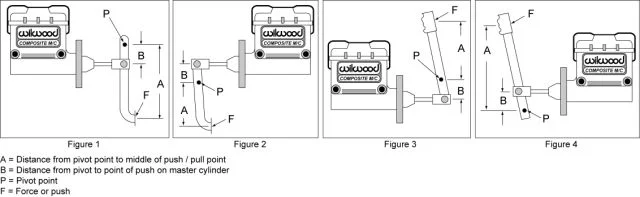
A = Distance from pivot point to middle of push / pull point
B = Distance from pivot to point of push on master cylinder
P = Pivot point
F = Force or push
Pedal Ratio is determined by dividing length “A” by length “B”. The amount of force at “F” determines the force to the master cylinders
Now that we know the math, can you explain a common set up for our readers?
Carl Bush: A common set up that could be found on a weekly show short track asphalt car is to use the example above with 1.75” piston calipers on the front with a 7/8” bore master cylinder, and a pair of 1.38” piston calipers on the rear with a 1” master cylinder. A 6:1 floor mount pedal ratio is also common. We have already determined that the 1.75 pistons with a 7/8” master cylinder and a 6:1 pedal will give the driver an overall brake leverage of 48:1 on the front. If we use the same formulas with the 1 3/8” piston calipers and 1” master cylinder on the rear, that produces a total driver’s rear leverage ratio of 22.75:1. When we compare the 48:1 ratio in the front, to the 22.75:1 ratio in the rear, we see that the car will be baselined with a front to rear static leverage bias of 67.8%, as long as the balance bar is centered and equal force is being applied to both master cylinders. You can substitute any combination of parts and their sizes to determine the exact influence they will have on the baseline static bias ratio.
Four Piston Calipers
Four piston calipers can usually be found with piston sizes from 1.125″ to 1.875″. The area of two pistons on one side of the caliper determine the calipers influence on clamping capability.
How do we use pressure to determine brake bias?
Carl Bush: Although racing with a perfectly centered balance bar is the ideal goal, it seldom happens in reality. Besides, one of the advantages in using an adjustable balance bar is having the ability to adjust that leverage to optimize handling and driver comfort on track. Trying to measure the post-race leverage split at the balance bar is difficult and unrealistic. However, using pressure gauges to measure pressure differentials s at any given balance bar setting is relatively simple. The brake gauges will show the actual pressure split in the car based on the balance bar adjustments made by the driver. Those pressures can then be multiplied by the effective caliper piston bore areas to calculate the last on-track static bias settings.
Going back to our (common setup) example, if we apply 50 pounds of leg force against a 6:1 pedal, we will generate 300 total pounds of force against the balance bar. If the balance bar is perfectly centered, it will distribute that force equally to each master cylinder. With each master cylinder receiving an equal force amount of 150 pounds, the 7/8” master cylinder should produce 250 PSI (Jeff’s math: 250 PSI comes from 150 divided by .6 which is the 7/8” master cylinder math result) while the rear 1” master cylinder produces 192 PSI (Jeff’s math: 192 PSI comes from 150 divided by .785 which is the 1” master cylinder math result). In practical use of gauges, you can use any level of effort and pressure for your comparisons. The end result will be the same.
When the front pressure of 250 PSI from the 7/8” master cylinder is multiplied by the 4.8” inches of caliper bore area of the front 1.75” piston front calipers, we get a front clamping force of 1200. On the rear, we will have 192 PSI x 2.97” caliper area or 570 pounds of rear caliper clamping force. When comparing the these front to rear clamping force total in the same way you would compare wheel weights for balance, we would see that this car has a total of 1770 pounds of caliper clamping force at these line pressures with 1200 pounds or 67.8 % on the front. It’s that same static bias ratio that was measured using the overall driver leverage ratios.
Now, if every car and driver had the same braking requirements and pedal feel preferences, we would never need to adjust anything. But, every car and every driver are unique and adjustments will get made.
The ratio examples that have been used here are very common in many short track asphalt cars. But your car, for a wide variety of reasons, may have quite different requirements. As a racer or crew chief, you can use these formulas to map the existing brake setup on your own race car, and then make calculated decisions when the desired handling or driver feel isn’t being delivered. The inability to reach the desired bias or driver’s feel of the pedal is the indication you will need to evaluate your component selection and consider possible alternatives. By using the formulas in these examples, you can accurately calculate what affects a component change will make to your existing baseline, and record those final ratios in your records to use for future adjustments and set up for any given track type or conditions.
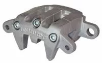
Metric Caliper
Calipers such as this metric replacement only have one piston on one side. The calculation of their clamping capability still uses the same formula.
Closing
As you can see, using the experience of you brake manufacturer is very valuable. Still, when you breakdown the math it is not all that hard. By understanding the pressures, bore areas and ratios you can improve your understanding of the brake system. A thorough understanding will help you to make improvements to an existing car or transfer learned knowledge to a new car. Be taking the time to understand the basic math behind the braking system you can calculate and record winning brake set ups. Slowing down to do the math will help you to go fast.