quench area:
A zone in the combustion chamber where the piston at top dead center is very close to the cylinder head. Because the piston and cylinder head is cooler than the unburned part of the fuel-air mixture (i.e., end gas), they pull the heat from the end gas. Because the end gas is now cooler, detonation is quenched or reduced. However, the process does form unburned hydrocarbons.
BTW, When a head gasket thickness is listed its supposed to be the compressed gasket thickness
keep in mind it assumes you use the factory heads with the matched factory head bolts torqued to the factory suggested torque settings,this can be important in determining quench distance.
SQUISH
An area in the combustion chamber of some engines where the piston squishes or squeezes part of the fuel-air mixture at the end of the compression stroke. As the piston approaches top dead center, the mixture is pushed out of the squish area and this promotes turbulence, further mixing of the fuel-air mixture and more efficient combustion
run less than about .035 thousands and at high rpm levels the pistons might hit the cylinder heads, run more than about .044 thousands the QUENCH effect of forceing the fuel air mix to the center of the cylinder from the cylinders edge area looses both speed and effectiveness, remember the quench area must be so tight that virtually all the fuel/air mix is forced (squished) into the center area and none is allowed to burn untill its squirted into the burn area increaseing turbulance and burn efficiency
in theory the much better quench, combined with the shorter more compact area the flame front needs to cover and the far higher turbulance combine to allow more of the pressure to build AFTER the crank passes TDC on the end of compression and begining of the power stroke
its mostly an advantage in that you get a more even and FASTER burn in the cylinder and less chance of detonation, simply because both the lower time and faster pressure curves favor the ignition flame front vs detonation
look, it takes approximately 40 thousands of a second for the flame from the ignition to cross a 4.25" bore,at low rpms and still takes about 15 milliseconds at high RPM due to the much faster movement of the compressed fuel air mix in the cylinders, lets look at what that means
if the chevy plug is located 4/5ths of the way to one side thats a time of about 32 thousands for the pressure to build as the flame travels 3.4" in the chevy but in a compact combustion chamber it could only take the cylinder flame front less than 10-20 thousands of a second to travel acrossed the combustion chamber for a complete burn at low rpms, this of course speeds up as the swirl and turbulance increase with increased engine RPMs but the ratios stay similar. this results in more useable energy WORKING on the piston AFTER IT PASSES TOP DEAD CENTER ON THE POWER STROKE. BUT MODERN WEDGE combustion chambers use increased QUENCH to speed the flame front and lower the burn time combined with a smaller combustion chambers.
the differance may be easier to grasp if you think of the quench area as a significant part of the total combustion chamber voluum,thats forcing its potential fuel/air mix into the central combustion chamber as a jet of highly compressed F/A mix, like the differance between lighting a cup of gasoline by simply placing it next to a camp fire vs throwing it violently into a camp fire
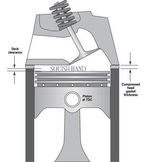
it should be rather obvious that youll need to know the exact distance the piston deck sits at TDC ,above or below the block deck surface and the valve notch recess or pop-up dome volume of the piston to do accurate quench or compression calculations
the quench (squish) at .030 would be unlikely to be a problem from the octane being to low, angle, but rather a potential for the piston to head contact as the rpms build and the rods stretch on the exhaust strokes where theres little compression to slow the rod stretch as they play (crack the whip) at high rpms and if you don,t think rods and pistons expand under high rpm and high heat then youve probably never seen the marks the heads quench areas leaves on heads/pistons at quench distances lower than about .035 which Ive found its best to exceed and stay in the .038-.042 range.
yes its entirely possible to run a .030 quench, but you better be running top quality components and measure very carefully.
get out a .030 feeler gauge and look at it on edge then rock the piston in the bore slightly and you think about it a bit.
http://em-ntserver.unl.edu/Mechanic...ion and Compression in Connecting Rods VI.htm
the quench/squish area is generally located opposite the spark plug location side of the bore, and theres generally a matching flat area on the combustion chamber
here the dome and spark plug side is on the right and the flat quench/squish is on the left

heres a cylinder head

the spark plug and dome goes to the exhaust side,(lower edge) the quench squish area is the matching flat area towards the intake on these sbc heads (upper edge in this picture)
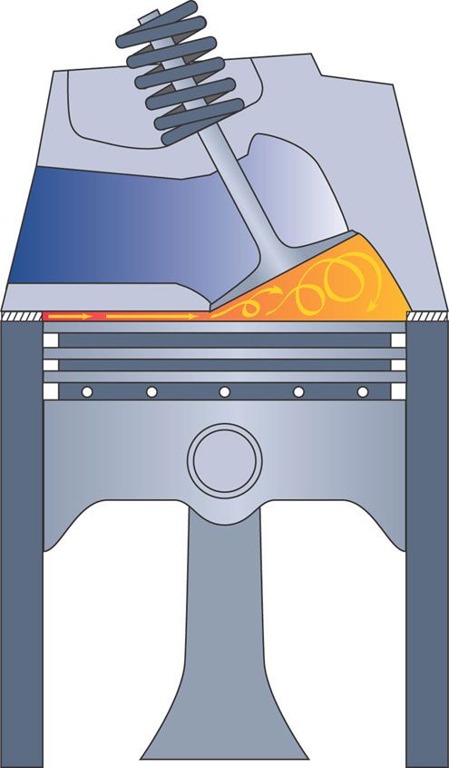
the idea, is that as the piston almost impacts the head the two flat areas force the cylinder voluum trapped between the flat areas violently toward the spark plug , this speeds the burn rate and tends to limit detonation
think of clapping your hands together violently with a raw egg in your palm, that raw egg will be forced away from the impending impact and squezzed out to spray to the sides, the cylinders voluum get sprayed the same way but limited by the bore and chamber in only towards the sparkplug direction, thus a high velocity mist of gas and air gets thrown into the area of ignition just as the burn starts, speeding the burn rate and lowering the distance the flame must cross
look at this picture, in a real engine the distance is very tight unlike the diagram and a good percentage of the cylinder voluum is compressed and forced into the dome/spark plug area
HOW DO YOU CHECK??
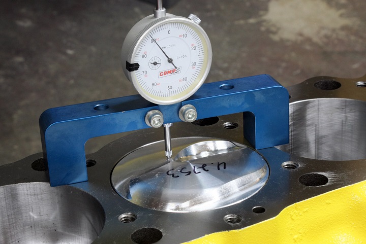
generally you measure the piston to block/deck height and then add the compressed head gasket thickness to the deck height distance to find the heads distance from the piston, but cross check with
a dial indicator on a deck bridge
http://store.summitracing.com/partdetail.asp?autofilter=1&part=PRO-66797&N=700+115&autoview=sku

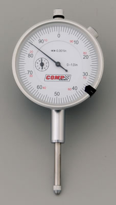
and a dial indicator
http://store.summitracing.com/partd...part=PRO-66962&N=700+-111345+115&autoview=sku
and re- check with plasti-gage during the pre assembly

btw spray the bearing and the crank surfaces, and the plastigauge with WD40 before you measure clearances and it won,t tend to stick as much
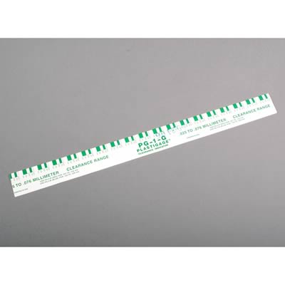
and before someone points out that plastigage won,t measure .038-.042, yeah! your correct by itself it wont but Ive cut dime size end tabs from a cheap feeler gauge
http://www.mytoolstore.com/kd/kdfeel01.html

and I usually use a .035 tab with a cross of plastigauge on top set on the quench area, its easily placed and removed and measured after spining the engine over and theres no chance of damage to the piston or head,
lots of guys just use soft solder and a machinists mic., and it works fine in most cases, the potential problem with that is that solder forces the piston to compress the solder and it takes a good deal MORE force to compress solder than a thin thread of plastic, when the rods in compression youll get a similar clearance, but when the rods whipping the piston around on the exhaust stroke under TENSION that quench distance tends to be closer to the head as the rod,piston and clearances tend to stretch out due to heat and inertial loads due to centrifical forces, you need to be sure the piston wont hit the head on both the exhaust and compression strokes and holding the piston down, away from the head crushing solder tends to give a slighly wider clearance because it tends to rock the piston in its bore, firmly away from the quench clearance on its piston pin.
yeah! Ive done it both ways and the differance is minor but there is still a differance of a couple thousands, probably not significant in most cases but get that clearance real tight and it might be critical info to know
A zone in the combustion chamber where the piston at top dead center is very close to the cylinder head. Because the piston and cylinder head is cooler than the unburned part of the fuel-air mixture (i.e., end gas), they pull the heat from the end gas. Because the end gas is now cooler, detonation is quenched or reduced. However, the process does form unburned hydrocarbons.
BTW, When a head gasket thickness is listed its supposed to be the compressed gasket thickness
keep in mind it assumes you use the factory heads with the matched factory head bolts torqued to the factory suggested torque settings,this can be important in determining quench distance.
SQUISH
An area in the combustion chamber of some engines where the piston squishes or squeezes part of the fuel-air mixture at the end of the compression stroke. As the piston approaches top dead center, the mixture is pushed out of the squish area and this promotes turbulence, further mixing of the fuel-air mixture and more efficient combustion
run less than about .035 thousands and at high rpm levels the pistons might hit the cylinder heads, run more than about .044 thousands the QUENCH effect of forceing the fuel air mix to the center of the cylinder from the cylinders edge area looses both speed and effectiveness, remember the quench area must be so tight that virtually all the fuel/air mix is forced (squished) into the center area and none is allowed to burn untill its squirted into the burn area increaseing turbulance and burn efficiency
in theory the much better quench, combined with the shorter more compact area the flame front needs to cover and the far higher turbulance combine to allow more of the pressure to build AFTER the crank passes TDC on the end of compression and begining of the power stroke
its mostly an advantage in that you get a more even and FASTER burn in the cylinder and less chance of detonation, simply because both the lower time and faster pressure curves favor the ignition flame front vs detonation
look, it takes approximately 40 thousands of a second for the flame from the ignition to cross a 4.25" bore,at low rpms and still takes about 15 milliseconds at high RPM due to the much faster movement of the compressed fuel air mix in the cylinders, lets look at what that means
if the chevy plug is located 4/5ths of the way to one side thats a time of about 32 thousands for the pressure to build as the flame travels 3.4" in the chevy but in a compact combustion chamber it could only take the cylinder flame front less than 10-20 thousands of a second to travel acrossed the combustion chamber for a complete burn at low rpms, this of course speeds up as the swirl and turbulance increase with increased engine RPMs but the ratios stay similar. this results in more useable energy WORKING on the piston AFTER IT PASSES TOP DEAD CENTER ON THE POWER STROKE. BUT MODERN WEDGE combustion chambers use increased QUENCH to speed the flame front and lower the burn time combined with a smaller combustion chambers.
the differance may be easier to grasp if you think of the quench area as a significant part of the total combustion chamber voluum,thats forcing its potential fuel/air mix into the central combustion chamber as a jet of highly compressed F/A mix, like the differance between lighting a cup of gasoline by simply placing it next to a camp fire vs throwing it violently into a camp fire
it should be rather obvious that youll need to know the exact distance the piston deck sits at TDC ,above or below the block deck surface and the valve notch recess or pop-up dome volume of the piston to do accurate quench or compression calculations
the quench (squish) at .030 would be unlikely to be a problem from the octane being to low, angle, but rather a potential for the piston to head contact as the rpms build and the rods stretch on the exhaust strokes where theres little compression to slow the rod stretch as they play (crack the whip) at high rpms and if you don,t think rods and pistons expand under high rpm and high heat then youve probably never seen the marks the heads quench areas leaves on heads/pistons at quench distances lower than about .035 which Ive found its best to exceed and stay in the .038-.042 range.
yes its entirely possible to run a .030 quench, but you better be running top quality components and measure very carefully.
get out a .030 feeler gauge and look at it on edge then rock the piston in the bore slightly and you think about it a bit.
http://em-ntserver.unl.edu/Mechanic...ion and Compression in Connecting Rods VI.htm
the quench/squish area is generally located opposite the spark plug location side of the bore, and theres generally a matching flat area on the combustion chamber
here the dome and spark plug side is on the right and the flat quench/squish is on the left
heres a cylinder head
the spark plug and dome goes to the exhaust side,(lower edge) the quench squish area is the matching flat area towards the intake on these sbc heads (upper edge in this picture)
the idea, is that as the piston almost impacts the head the two flat areas force the cylinder voluum trapped between the flat areas violently toward the spark plug , this speeds the burn rate and tends to limit detonation
think of clapping your hands together violently with a raw egg in your palm, that raw egg will be forced away from the impending impact and squezzed out to spray to the sides, the cylinders voluum get sprayed the same way but limited by the bore and chamber in only towards the sparkplug direction, thus a high velocity mist of gas and air gets thrown into the area of ignition just as the burn starts, speeding the burn rate and lowering the distance the flame must cross
look at this picture, in a real engine the distance is very tight unlike the diagram and a good percentage of the cylinder voluum is compressed and forced into the dome/spark plug area
HOW DO YOU CHECK??
generally you measure the piston to block/deck height and then add the compressed head gasket thickness to the deck height distance to find the heads distance from the piston, but cross check with
a dial indicator on a deck bridge
http://store.summitracing.com/partdetail.asp?autofilter=1&part=PRO-66797&N=700+115&autoview=sku
and a dial indicator
http://store.summitracing.com/partd...part=PRO-66962&N=700+-111345+115&autoview=sku
and re- check with plasti-gage during the pre assembly
btw spray the bearing and the crank surfaces, and the plastigauge with WD40 before you measure clearances and it won,t tend to stick as much
and before someone points out that plastigage won,t measure .038-.042, yeah! your correct by itself it wont but Ive cut dime size end tabs from a cheap feeler gauge
http://www.mytoolstore.com/kd/kdfeel01.html
and I usually use a .035 tab with a cross of plastigauge on top set on the quench area, its easily placed and removed and measured after spining the engine over and theres no chance of damage to the piston or head,
lots of guys just use soft solder and a machinists mic., and it works fine in most cases, the potential problem with that is that solder forces the piston to compress the solder and it takes a good deal MORE force to compress solder than a thin thread of plastic, when the rods in compression youll get a similar clearance, but when the rods whipping the piston around on the exhaust stroke under TENSION that quench distance tends to be closer to the head as the rod,piston and clearances tend to stretch out due to heat and inertial loads due to centrifical forces, you need to be sure the piston wont hit the head on both the exhaust and compression strokes and holding the piston down, away from the head crushing solder tends to give a slighly wider clearance because it tends to rock the piston in its bore, firmly away from the quench clearance on its piston pin.
yeah! Ive done it both ways and the differance is minor but there is still a differance of a couple thousands, probably not significant in most cases but get that clearance real tight and it might be critical info to know