Replacing Hard Brake Lines On C4 Corvette

Grumpy

The Grumpy Grease Monkey mechanical engineer.
Staff member
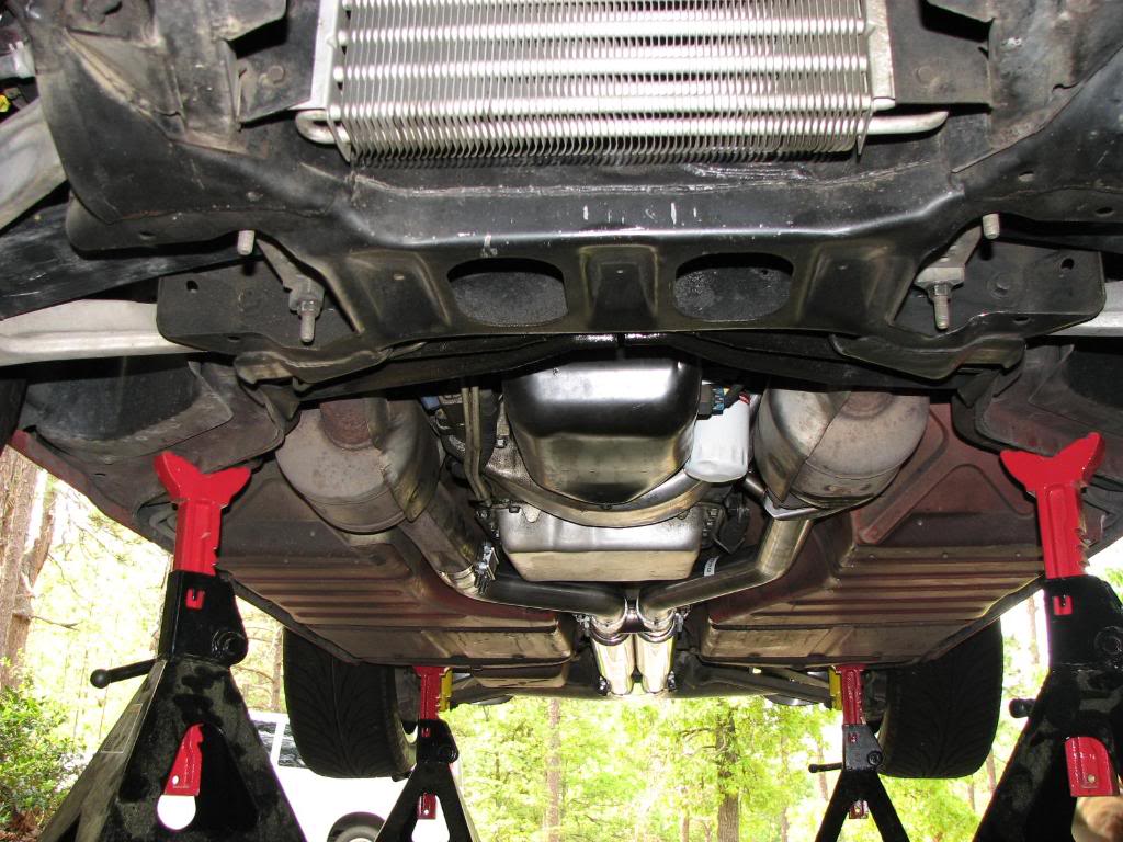
if your having issues with the corvettes brakes Id suggest,you start by putting the car up on a two post lift or jack stands and remove the wheels and do a careful inspection,
look for leakage,
look at the calipers and pads and it helps to have a buddy to work the brakes during the inspection process. and bleed the brakes, flushing out old brake fluid that might be moisture contaminated.
think logically and make sure the brakes get bled and your not low on brake fluid.
http://garage.grumpysperformance.co...s-and-trouble-shooting-them.15862/#post-95362

http://garage.grumpysperformance.com/index.php?threads/brake-and-fuel-line-flaring.11236/#post-50743

http://garage.grumpysperformance.co...ubing-fuel-lines-and-flaring.1030/#post-35905


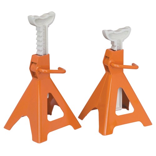
Ive used 6 12 ton rated jack stands like these for almost 20 years now in my shop they are well made
http://www.zr1netregistry.com/jackupzr1.htm
http://www.homedepot.com/buy/tools-hard ... 70912.html

http://www.northerntool.com/shop/tools/ ... _200330725
http://www.harborfreight.com/12-ton-jac ... 34924.html
12tonstand.jpg

vettejack1.jpg


http://www.superchevy.com/how-to/brakes/1807-restore-brakes-factory-spec-long-neglected-1995-c4/

https://www.summitracing.com/search/part-type/brake-lines-sets/make/chevrolet/model/corvette

https://www.corvsport.com/1984-corvette-diy-guide-braking/

https://www.amazon.com/Nickel-Coppe...ocphy=9012039&hvtargid=pla-571026391156&psc=1

https://www.zip-corvette.com/84-96-c4/brakes/brake-lines.html


9413505.jpg
 
Last edited:
CUNIFER
http://www.brakeconnect.com/cunifer-brake-line

The new ‘old’ material for brake lines

Last month I mentioned a `new’ product that has been around for years – only nobody knew about it. It is a material known as Cunifer – an alloy of copper and nickel with a bit of iron and manganese thrown in for good measure.


In the world of metallurgy, this material goes by the names of Copper-Nickel CA 706, Cupro Nickel 10%, and C70600 and, as mentioned Cunifer alloy. In actuality, the alloy consists of 88.7% cop-per (Cu), 10% nickel (NI) and 1.3% iron (Fe ),although I have seen specifications listing 0.8/0 manganese (Mn).

For those of you who are not chemists or metallurgists, the previous paragraph was probably wasted, but it is important in that this special alloy makes a wonderful substitute for the traditional steel brake tubes used on our cars.

Let’s step back seventy or eighty years to the 1920s. Of course most automotive brake systems of the time were mechanical, but hydraulic systems were beginning to make their appearance. The lines used to carry the hydraulic brake fluid were generally either copper or brass (a copper/zinc alloy). These lines were strong and easy to work with – they could readily be bent, flared, soft-soldered or brazed.

In the 1930s it was realized that both copper and brass had a tendency to work harden (more on that below) making the metal structurally unsafe for an automotive component on which your life depended. Steel lines were substituted on brake systems. They were strong and did not work harden, but they were difficult to work with, unless one had special equipment not normally available to the hobbyist. Besides being difficult to bend to fit, steel lines were extremely susceptible to corrosion. Salt and other chemicals used on the roads to melt ice and snow played havoc with steel. The reaction was to coat the steel with a corrosion resistant material. Over the years tern (a lead-tin alloy), zinc and epoxies were tied, with more or less success. Their biggest drawbacks were that all of the coatings were susceptible to damage from stones and other road debris and to scratching of the surface when working on the car. Once the coating was breached, it was like working with uncoated steel. The second problem (and one not generally addressed by those making the determination of choice of materials) was internal corrosion. We know that brake fluid – DOT 3 or 4 will absorb ambient moisture and hold it in suspension within the hydraulic system allowing it to do its insidious thing within our brake lines. I have been told by brake specialists that more line corrosion occurs from within the brake tubes than from without.

When this corrosion occurs, the lines leak and the brakes fail. It’s that simple. The dual brake system provides a back-up, but it’s not the answer. Replacing the brake lines is really the only way to go. Once corrosion has shown up in one line, you can be sure that it’s happening elsewhere in the system. For us it has meant putting the car out of service while the entire system is replaced – either in a professional shop or in our garages. The rotted steel lines are generally replaced with brand new pre- measured steel lines available from our local parts store. Since these lines come with fittings already installed, we have to work with what they sell us. Overly long lines can be ‘looped’ to take up slack, but bending steel lines, especially tight bends, often results in kinked lines that are suitable only as trash. Very few of us have the equipment to double flare a steel brake line, and often, if our wallets are fast enough, we can purchase complete brake lines all bent and shaped to fit our particular model or car.

In the 1970s the Swedish automobile regulators realized that the high degree of corrosion was downright dangerous. All kinds of studies were done (no, I won’t bore you with statistics) and a new material was tried Cunifer

This alloy provided superior corrosion resistance to steel, was malleable, easy to work with and easy to flare, was strong and had most of the benefits of copper tubing without the liability of work hardening. The inclusion of the nickel, steel and manganese made it stronger than copper alone, but still short of the strength of steel. The Cupronickel alloy is softer than steel and so more subject to damage from rocks and stones being kicked up from the road than steel. Fortunately it is a rather easy problem to fix. A special protective shield – in fact, a stainless steel spring – fits over the metal brake line at points of exposure to road hazard Where the line goes through the frame of the car, or is protected by the frame, this is not necessary. Brakes lines (rigid brake lines as opposed to flexible rubber lines) do not have specific testing requirements, but tests on the C70600 material have shown it to be more than adequate for our needs. More on that and more on governmental regulations in a few paragraphs

The Swedish car manufacturer, Volvo, began using the 90/10 alloy for brake lines in 1976 and they began tracking brake failures based on eight-year old Volvos. Brake failures dropped markedly once this new material was used. In subsequent years, other manufacturers in Europe have begun the switch to Copper-nickel from steel lines, and currently Rolls-Royce, Aston- Martin, Porsche, Audi and, of course ‘Volvo, are using this material in their new car production.

The bar graph above depicts the percentage of vehicles falling safety Inspections because of defects in the brake systems of eight year old Volvo passenger cars. The 1970 model cars had tern-coated steel tubes. 1971 models had zince coated steel tubes. 1976 models used copper-nickel tubes. The reduction in defects is dramatic.

Why, then, are U.S. manufacturers not using Cunifer rather than steel for brake lines? The most obvious answer is cost. Steel is still considerably less expensive than Cupra-Nickel 90-10, and at the manufacturing level with everything highly auto mated, the problems of bending and flaring don’t present problems. “But,” you ask, “what about DOT and SAE approval? a very good question Ready for this. At the present time DOT does not have any regulations covering rigid brake lines. They do for flexible lines, but not for the rigid metal ones. In the typical `government-speak’ that seems to be the written language of all governmental agencies, we were advised that, “NHTSA (National Highway Traffic Safety Administration – a division of Department of Transportation) has brake hose standards for flexible’ hoses only (and more recently for plastic hoses too). But there is no federal standard for ‘metal’ tubing. That said, that doesn’t mean that defective metal tubes can be used in braking systems because if they fail due to a defect (corrosion, bursting, etc.) then that is a defect and a violation of the ,government’s motor vehicle safety statutes.” Follow that? In other words, if it works, its fine, but if it fails then it’s defective and not okay. And the Society of Automotive Engineers (SAE): “SAE does not ‘approve’ products. We are a standards organization; therefore we create standards for the auto motive industry that are voluntary. We do not require they be used.”

Let’s get back to our needs then. So C70600 is acceptable for hydraulic brake lines. There is one factor that we do have to consider though when deciding to rip out that brand-new steel system that we just installed and replace it with Copper-nickel. We don’t (generally) use our old, collectible cars on icy, snowy, salt-encrusted roads. The cars are tucked away for the winter in a nice, warm, preferably heated garage, up on blocks or jack stands. But while we’re sitting in front of a nice warm fire, the moisture in the brake fluid is working at the inside of the steel tubing. The outside may be coated with tern or epoxy, but not the inside. Maybe, when you com pletely re-did your brakes you used Silicon (DOT 5) brake fluid. Then relax and pour yourself another hot toddy. Your brake system is okay. DOT 5 does not absorb water.

I sure took a long way around to get here but the bottom line is that it looks like Copper-nickel tubing is perfectly acceptable and more than adequate for our brake systems. It’s strong, corrosion resistant, easy to work, remains pliable, and can be readily flared (or even soldered or brazed). I’m going to hedge a little bit here. Although 90-10 doesn’t work harden as readily as copper alone, it does get stiffer as it is bent. Three or four bends and it is not nearly as flexible as it was to start. But real istically that shouldn’t be a problem, because if you have to bend and re bend and again re bend a section of brake line when installing it, then maybe you should let a professional do your brakes.

Two last points. Stainless steel brake lines provide the strength, durability, corrosion resistance and appearance for an excellent brake job. But Stainless is not a material for the home hobbyist to work. You can buy pre-formed, pre-bent brake lines to fit your particular car, and it’s an easy bolt-together project. But it is not cheap!

Next, what does Copper-nickel look like? Well, if you leave it alone, it looks like and colors like copper. That’s great for an authentic looking restoration. But if you polish it, it will take on an extremely bright copper gleam. If that’s what you want.

The question now comes up, “Where can I buy this miracle product?” Fortunately, that’s an easy one. I was recently speaking with a well-known restoration shop manager and we were discussing Cunifer. He knew what it was right away, and told me that he had a coil of it squirreled away in a back room – stuff he had ordered from Europe.

You don’t have to go to that trouble. Brake and Equipment (see ad on page 48) stocks it in a variety of ‘diameters and will sell it by the foot. So if you need 27 feet of it you can buy 27 feet. You don’t have to buy two 25 foot coils and let the remainder sit on a shelf, nor do you have to buy two ten foot lengths, two three foot lengths and a fifteen inch length and

How Did We ‘Rediscover’ Cunifer? As we indicated Cunifer brake lines are not new. They have been used in Europe, especially in England for many years. But they are ‘new’ to the United States. Why and how did we happen to rediscover this product?

Perhaps we get into a rut; we get used to doing something one way, and it’s just too much trouble to change. Or maybe, despite superb international communications, we are a little lax in getting information from ‘the old country’. But whatever the reason, copper-nickel brake lines have been in use in England, Australia and more than likely in other countries with a heavy British influence.

Fred Anderson, an American citizen raised and educated in Australia, recently moved to the United States from the Sydney area and wondered why we weren’t using Cunifer here as he had been doing in Australia.

Without belaboring the background research that Mr. Anderson did, he determined that there was, in fact, one other source of Cunifer brake tubing here in the U.S., but that company was purchasing its brake tubing from England. With the extremely unfavorable monetary exchange rate, freight, duties, etc. this material was quite expensive when resold to the U.S. buyer.

Fred’s newly-founded company – about five years old, Brake Quip out of Tennessee contracted with a major manufacturer of tubing to make the Nickel-Copper lron alloy for him, to his thin-walled specifications. Today Brake Quip is the only company manufacturing Cunifer brake tubing in the United States for the aftermarket, and it is selling it through its distributors at prices highly competitive with steel lines.

“It was a matter of recognizing a void in the market and doing the legwork to fill that void” reports Mr. Anderson. “We found one of the best companies in the country to make C70600 (Copper-Nickel) tubing to our high specifications. That product, in conjunction with our line of specialized brake fittings, installation equipment then bend it to fit as you do with over-the-counter pre‑formed brake lines. You can buy just what you need, flare it yourself and install it as easily as you would regular copper line. When you buy it though make sure that you order the correct fittings for brakes. They ARE NOT the same as the plumbing fittings that you buy at the local home building center. Brake fittings require special flares at the ends. Compression fittings are NOT acceptable, nor are single flares. A double flare is much stronger than a single flare, and is not a lot more difficult to make.

Next month we will discuss how to make a double flare, why they are necessary and the tools that are needed to make a good, strong double flare and flex-lines made us a natural source for the brake industry. We don’t sell anything at retail; everything that we manufacture, or have manufactured to our specifications is sold to or through nationwide distributors, o f whom, Brake and Equipment in Minneapolis is one of the largest.”

Well, that’s how the product came to the United States, but what brought it to the attention of Skinned Knuckles? Brake and Equipment wanted a larger display ad and that led to a discussion of what a larger ad should contain. Jim Terrell of Brake and Equipment was very high on their new product, Ezi-Bend, a copper-based brake line with which they have been extremely successful.

We talked about the inherent problem of work hardening of copper, but Jim assured us that they haven’t found that to be a factor. We discussed the ease of working Cunifer; whether it was suitable for the home hobbyist and whether it could be double-flared, an important consideration in making hydraulic brake lines. From there we went directly to the manufacturer, Brake Quip, and got their input on the product. Not willing to accept anyone’s word that Cunifer was acceptable under the regulations formulated and administered by both SAE (Society of Automotive Engineers) and DOT (Department o Transportation [National Highway Safety Administration within the DOT actually)), we contacted both organizations.

We also attempted to contact Volvo, Audi, Rolls- Royce and Porsche to confirm that they were indeed using Copper-Nickel brake lines. So far, we have not been very successful in getting a response directly from these OEM sources, but we’re still trying.

Bottom line, though, is we have uncovered a product that could, should and I expect, will be an important part of future restorations. We would be very interested in hearing of your personal experiences with this product. Let us know how your brake restoration projects progress using Cunifer.


It may be hard to believe but it’s so easy to bend duplicating your existing line is borderline fun. Replace your brake line with Cunifer Tube and never do it again.
 
Its the only available aftermarket type of hard brake line in Sweden (maybe Europe) since at least 40 years, and i have never heard of any problems. It will outlive the vehicle :D
 
http://www.superchevy.com/how-to/19239
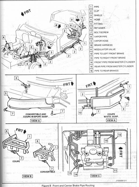
47674080d1307205966-1988-corvette-c4-abs-modulator-valve-abs-pipe-routing.jpg

s-l1600.jpg


s-l1600.jpg

9413505.jpg


9413511.jpg


Well let's get started...

ABS

Follow cautions on/around the SIR systems.
Certain ABS components are not designed to be serviced.
Always reinstall fasteners at the same location removed from. Replace with exact part or of equal or greater strength. Follow non-use, locking compound, and torque call outs.

General Description
The ECBM monitors performance, logic and circuitry, to determine malfunctions and set CODES.

Most ABS self-diagnostics are performed by the ABS Controller after 1.7mph.

Built-In-Test Equipment (BITE) is performed once each IGN cycle at 3-11mph, cycling each solenoid valve and pump motor as follows:

IGN ON the ECBM grounds and activates solenoid relay.
3-11mph, the ECBM test solenoid valves & hydraulic modulator pump (usually can be heard).
If the pump or solenoid fails, the ABS is disabled, CODE set, and SERVICE ABS, illuminates.

When the EBCm receives any Wheel Speed Sensor (WSS) signal, it checks WSS output. If any WSS signal is missing, ABS is disabled, CODE set, with SERVICE ABS lamp.

On vehicle movement, the ECBM continuously monitors itself and:

Modulator Valves
WSS
Wiring Harness and relays
BAT voltage

If BAT voltage drops below 9v, ABS is disabled and SERVICE ABS lamp illuminates.

Each malfunction type has an associated fault CODE, which is a two digit number flashed (for '90) over the SERVICE ABS lamp in the DIC.

Fault CODES involving the solenoid valves and pump motor cannot be read at the DIC (the SERVICE ABS reamins ON) and require the Tech 1 Diagnostic Computer to retrieve CODES.

While the SERVICE ABS is ON, only normal power brakes operate (no ABS during diagnostics or driving).

Prelim Diagnostic Checks
Before using CODE diagnostic charts, CHECK:
STOP/HAZ, BRAKE, SIR, & CLUSTER fuses.
Fuseable link "J"
Pump Motor, ECBM, and Solenoid RELAYS are firmly seated.
ECBM connector is properly mated.
GND System
 
Last edited:
Roadrunr said:
... the use of the J35890 ABS tester and how to take out a ABS pump.
The '90 uses the J34029-A: High Impedance Digital Multimeter.
94-00101-A: Tech 1 Diagnostic Computer.
J 35592 Pinout Box

Is your J35890 ABS tester any of the above?

Testing the ABS Pump & Relay

Once the pump motor realy is grounded by the ECBM, it provides B+ to operate the pump. A CODE 61 sets if 12v is at the pump without relay activation, or if 12v is not present after relay activation within 60 milliseconds.

To check for Motor or Relay fault:
Correct Relay resistance
Stuck relay
OPEN in the Hydraulic Modulator circuit
GND
Correct Pump Motor resistance

IGN OFF
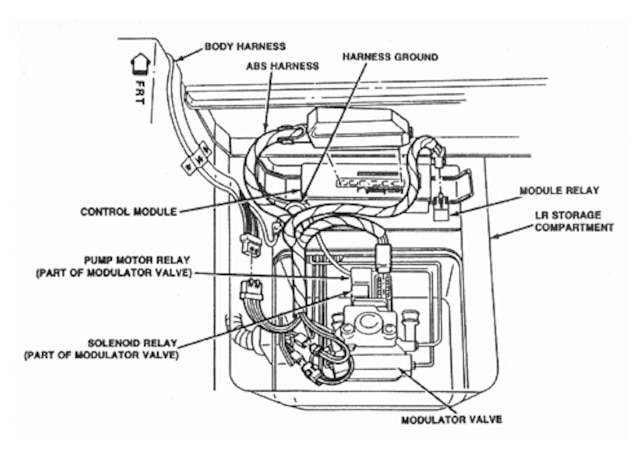
Remove Modulator cover and Motor Relay (4-pin)
Measure resistance between Motor Relay Pins 85 & 86. Is it 45-55 OHMS?

NO: Replace Motor
YES: Measure bet Valve Relay pins 30 & 87. Continuity: Replace Motor. No Continuity: Disconnect (DIS) connector (CON) from Hydraulic Modulator. Measure resistance on Modulator between:

Modulator pin 10 & Motor Relay CON PIN 87
Modulator pin 8 & Motor Relay CON PIN 86
Modulator pin 12 & Motor Relay CON PIN 85
Modulator pin 9 & Motor Relay CON PIN 30

More than 2 OHMS at any step: Replace Hydraulic Modulator Assy.

0-2 OHMS at each step:
Measure resistance bet Modulator GND wire CON on Modulator Pump and a good chassis GND. Is it at 0-2 OHMS? NO: Replace/repair GND wire. YES: DIS PUMP Motor CON on Modulator. Measure resistance bet PUMP Motor & GND. 3.5-4.5 OHMS? NO: Replace Hydraulic Modulator Assy. YES: continue diagnosis (6-13).


[CSM, 1990, 5E1-30]
 
ABS CODE 61 (Motor or Relay fault)

This test continues from above to check:

BAT Voltage available to the Pump Motor Relay.
Short to BAT in Relay feed circuit.
Potential OPEN or Short to GND in CKT 998.
Open, Short to B+, or Short to GND in CKT 913.
If CKT 998 problem is due to circuit itself or faulty ECBM.
Open, Short to B+, or Short to GND in CKT 985.

Reinstall Motor Relay on Modulator
Measure voltage bet Modulator CON pin 12 & GND. Approx. 12v? NO: Repair OPEN in CKT 2. YES:

IGN OFF
Measure voltage bet Modulator pin 10 & GND. Approx. 12v? YES: Repair SHORT to voltage in CKT 998. NO:

IGN ON
Measure voltage bet Modulator pin 10 & GND. Approx. 12v?

NO:
IGN OFF
Install J 35592 Pinout Box
Measure resistance bet Pinout Box pin 17 & 20. Continuity: Repair Short to GND in CKT 998. OPEN CIRCUIT: Measure resistance bet Pinout Box pin 17 & Modulator CON pin 10. 0-2 OHMS: Replace EBCM. OUTSIDE 2 OHMS: Repair OPEN in CKT 998.

YES:
IGN OFF
Install J 35592 Pinout Box
Measure resistance bet Pinout Box pin 28 & 20. Continuity: Repair Short to GND in CKT 913. OPEN CIRCUIT: Measure resistance bet Pinout Box pin 28 & Modulator CON pin 11. OUTSIDE 2 OHMS: Repair CKT 913. 0-2 OHMS: Measure voltage bet Pinout Box pin 28 & GND. Approx 12v? YES: Repair Short to voltage in CKT 913. NO: Measure resistance bet Pinout Box pin 14 & 20. Continuity: Repair Short to GND in CKT 985. OPEN CIRCUIT: Measure resistance bet Pinout Box pin 14 & Modulator CON pin 9. OUTSIDE 2 OHMS: Repair OPEN in CKT 985. 0-2 OHMS: Measure voltage bet Pinout Box pin 14 & GND. Approx 12v? YES: Repair Short to voltage in CKT 985. NO: Replace ECBM. Replace Hydraulic Modulator.
 
Roadrunr said:
... the use of the J35890 ABS tester...
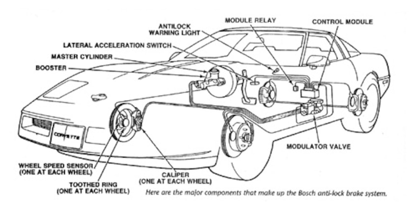
In 1986 Corvette introduced ABS Bosch II as standard equipment. 1987 through 1992 GM was using the Bosch III ABS system. By 1998, Corvette was running Bosch 5.3.

On the 5.3, the EBTCM or BPMV can both be replaced separately, but neither component is considered serviceable. So if an ABS solenoid valve, the pump or a relay fails, the whole BPMV assembly must be replaced.

20136b.gif


Here's a general guide for the Bosch III NOT CORVETTE SPECIFIC:

Overview

The ABS system consists of:
Electronic Brake Control Module (EBCM)
A hydraulic pump
ABS unit
Wheel sensors
About 1990, the Traction Control was integrated with the ABS system.
ABS pump relay
Stop light switch.

The ABS unit has several major components:
Sensor Block
Accumulator
Pressure Control Switch
Fluid Reservoir
Valve Body
Hydraulic Unit.

SYS Operation

Each time the car is started, messages and warning lights are tested. With IGN ON, 12v is realyed to the ABS pump. The pump pressurizes the hydraulic assist to operate the ABS system. The EBCM monitors pressure via the Pressure Control Switch, and signals (by relay) the pump ON/OFF to control pressure.

The accumulator stores pressurized fluid to assist braking. When the brake pedal is applied, the EBCM operates/monitors the system using various sensors from around the car. Under normal braking, the pump runs for a short time.

ABS braking occurs only when a wheel starts to skid. The wheel sensor detects the skid and signals the EBCM. The ABS opens the corresponding wheel valve to allow the wheel to roll. Then the wheel valve closes and braking is reapplied.

ABS Failure

There are four general categories of failure:

Loss of power assist.
Due to the ABS pump's not running, or insufficient pump pressure to run the ABS system.

Symptoms are a hard pedal with decreased stopping ability.

Loss of fluid as a result of a blown seal or ruptured brake line.
The pedal travel increases and/or goes to the floor, with corresponding fluid leakage under the car.

Error messages/warning lights illuminate with normal braking ability.

Error messages/warning lights illuminate with abnormal braking ability (reduced or inconsistent braking).

Simple Troubleshooting

ABS PUMP AND ACCUMULATOR

To determine if the ABS pump and accumulator are functioning within normal limits:

When the key is turned ON, the pump should run long enough to repressurize the system, and then shut off.

Locate the pump:
Turn the key ON (the pump may/may not run).
Completely depressurize the ABS system by turning the IGN OFF, then pump and release the brake pedal firmly at least 25 times. Normally, the pedal will go to the floor when you first starting pressing it. After a number of applications, it will come off the floor, and feel like you are building pressure. This is the point at which the system is depressurized.

Once the SYS is depressurized:
Using a watch with a second hand, turn IGN ON, without starting the car. The ABS pump should run 25-30 seconds, before turning OFF.

Depressurize the SYS by turning the key OFF, then count the number of times the brake pedal is pressed before you experience the change in pedal pressure (stops going all the way to the floor). A good accumulator should store 15 to 20 pumps before it is depressurized.

Further evaluation requires ABS pump to run for the above test. If the pump fails to run, the cause must be found and corrected before any further analysis can be performed.

HOW TO REPLACE THE ACCUMULATOR

Accumulators were originally designed as throwaways, but can be modified to be rechargeable. Recharged accumulators are available for much less than the price of a new accumulator. With new seals, they will give the same service as a brand new one, at less than half the price.

Tools you will need:
¼" drive ratchet, w/ ¼" drive 3" extension
¼" drive THIN WALL ¼" hex socket
#30 Torx bit (comes with magnetic Torx screwdriver with multiple bits)

If bleeding brakes: clear hose, glass jar, new brake fluid, DOT 3, 4, 5.1 only. DO NOT use SYNTHETIC brake fluid, it is not compatible with ABS.

To replace:
Key OFF
Depress brake pedal 25 times to completely depressurize system.

There are two Torx screws holding accumulator to hydraulic unit from up underneath.

Check size of Torx bit in screw head for proper fit. Assemble ratchet handle, 3" extension, ¼" socket, and #30 Torx bit to remove both screws. Be careful not to drop screws. Once the screws have started to come loose, ratchet can be removed, and screws turned out by gripping the end of the extension and turning them out much like a screwdriver. Be careful not to strip the screw heads. Keep the ratchet as straight as possible into the Torx head.

Wipe off plate on top of hydraulic unit after old accumulator is removed. Put new O-ring into port on bottom of recharged accumulator. Reinstall two screws and tighten. Very little brake fluid is lost. Turn key ON, and check for leaks. Time the length of time pump runs before it shuts off. It should be around 25 to 30 seconds.

To bleed hydraulic unit, which is a good idea, shut key OFF and depressurize system by pumping brake pedal 25 times.

Attach clear hose to bleeder fitting on passenger side of hydraulic unit. Take a glass jar. Add about 1" of new brake fluid to jar. Submerge end of clear hose in brake fluid in jar. Open bleeder screw, turn key ON, let fluid run until no bubbles are present, then shut off bleeder. Turn key OFF. Add brake fluid as necessary to full line on reservoir.

HOW TO REPLACE THE BOSCH III ABS SYSTEM

General description/overview ONLY:

Depressurize the SYS by depressing the brake pedal 25 times with the key OFF.
Disconnect BAT - TERMINAL
Disconnect the electrical connector to the ABS pump.
With a jar, pull the hose off the bottom of the brake fluid reservoir where it feeds the ABS pump.
Drain the reservoir drain into the jar.
Disconnect all brake lines.
Disconnect the two hoses to and from the ABS pump. Disconnect the electrical connector that goes to the top of the sensor block.
Disconnect the connector to the brake fluid reservoir.

If you have traction control, there will be more lines, and a traction control valve assembly. That stays in place and is reused. With traction control, there would also be an adapter on the bleeder screw port that must be reused from your old unit. Just make sure you reuse anything that’s different.

Remove/replace the ASSEMBLY.

When reattaching the lines, be very careful not to cross thread anything. Work with fingers only until the connection is started straight.

Go around all connections before powering up the system to make sure they are all tight. Make sure you use only DOT 3, 4, or 5.1 brake fluid to refill the systems. The seals in ABS systems are not compatible with silicone (synthetic) brake fluid.

Reconnect electrical wiring connectors and BAT GND.

To manually bleed (without a power bleeder or vacuum bleeder) the system after reinstallation:

First the ABS pump gets bled, key ON, until bubbles are gone. A clear hose gets attached to the pump bleeder screw, the end of this hose submerged in a jar with about an inch of clean brake fluid in the bottom. Open the bleeder screw on the pump, and let it run until it clears up. About 30 seconds at a time is all you should let the pump run. Let it rest for a minute, then another 30 seconds, etc. Generally three cycles of this will be enough. Keep the reservoir full, within 1/4 inch of the full line.

Next you bleed through the bleeder screw on the master cylinder. Again, have a clear hose on the bleeder, end submerged into a glass jar with clear brake fluid. Open the bleeder screw. Turn the key on, and let it run until fluid is clear of bubbles. 30 seconds on cycle, then rest.

With two people, turn the key OFF. The order of wheels is RR, LF, LR, RF. Attach clear hose to bleeder, end submerged in glass jar with 1" of brake fluid in it. Have an assistant pump pedal a few times, then hold, and open bleeder screw until flow stops. Tighten screw before pedal is released. Repeat as needed until fluid is clear and there are no more bubbles. Keep an eye on the fluid level in the reservoir.

C'ya
D
 
Back
Top