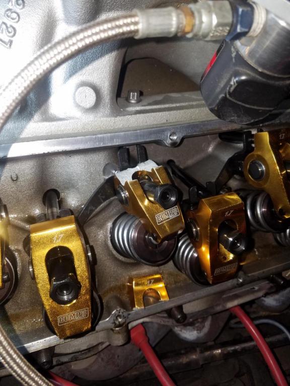
rocker/push rod wear issues

grumpyvette

Administrator
Staff member
KM said:
Put vortec heads on my L98 and ordered 1417 1.52 Roller Rockers and 7808 Pushrods from CompCams. Installed screw in rocker studs with guide tool before assembly of the engine. Checked valve geometry and the roller left a mark right on the center of the valve like its supposed to.
Oil pressure has always been strong, between 30-50 on the gauge. Assembly lube was used between the lifters and pushrods on installation.
I called Comp and they said they would replace them within 1 year of purchase, thats no problem. I am worried however, replacing them without figuring out what happened tends to yield the same results.
The valve lash was set initially to start the engine. At operating temperature, the rockers were backed off one by one and tightened until no ticking was heard
I used the Comp assembly lube on every rocker before installation.
As I adjusted the valves at operating temp, I observed the oil also. No problem there.
I did not check the rods for straightness, will do that tomorrow and let you know.
The oil may have been dirty, but it happened to every single one of them which leads me to believe its a tolerance problem somewhere.
Cam is 08-502-8 Compcam.
http://www.summitracing.com/parts/cca-0 ... /overview/
Retainer to valve checked on every valve, .561 being the smallest value I received on an intake valve. With 1.52 rockers I get max lift values of .502 Int & .509 Exh
BTW.IF YOUR BUILDING A SBC
http://brodix.com/heads-2/small-block-chevrolet-compatible-heads/ik-series
http://www.jegs.com/i/Brodix/158/1021001/10002/-1

http://garage.grumpysperformance.co...train-clearances-and-problems.528/#post-57678

brodix ph# 1-479-394-1075 (ALWAYS VERIFY PART NUMBERS SEVERAL,
TIMES FROM AT LEAST TWO SOURCES, BEFORE ORDERING PARTS)

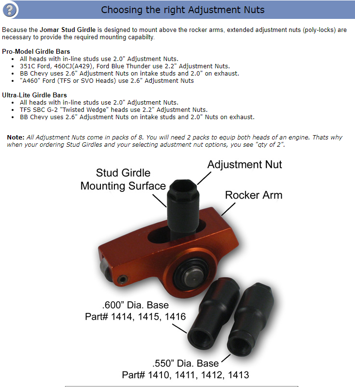
the brodix rock stud girdle is part # BR-6435 and LIST price is about $230 you can get it for less if you shop carefully
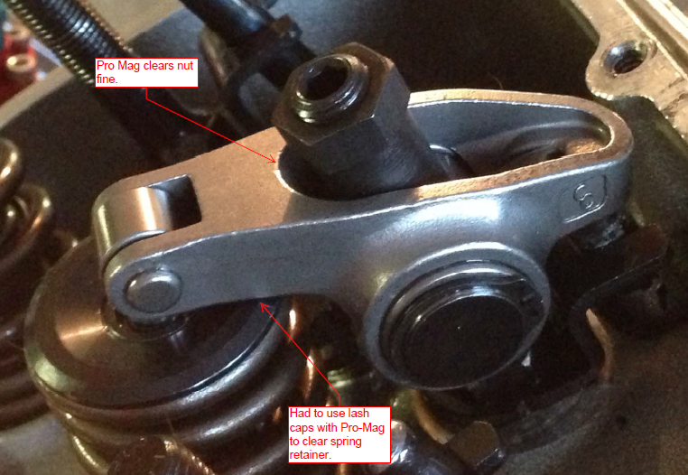
BE AWARE that the I.K. 200 heads were shipped with BOTH 3/8" and 7/16" rocker studs ,
and the poly locks for the 7/16" rocker studs ONLY fit that rocker stud girdle
obviously you need to verify what your heads have before you order the matching rocker stud girdle
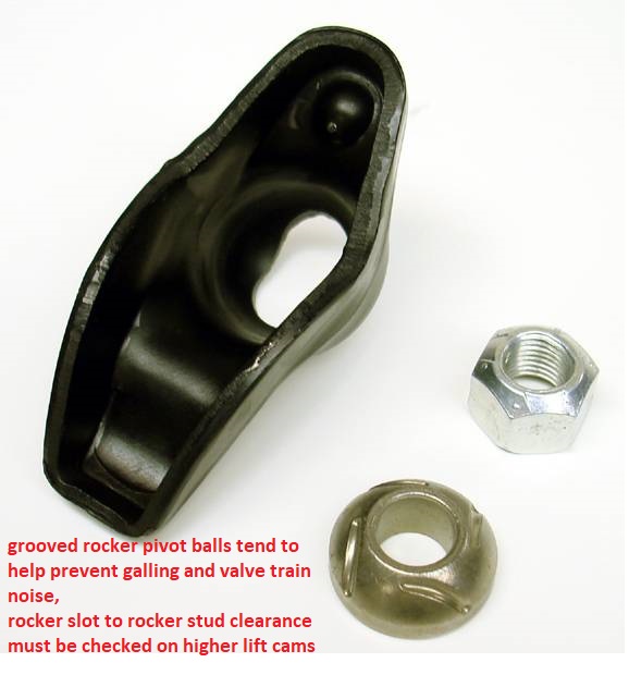
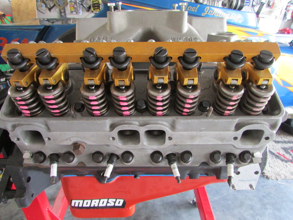
Verifying your engines clearances, and rocker geometry, and use of A rocker stud girdle and high quality roller rockers go a long way towards maintaining valve train durability
IMG_2071.jpg

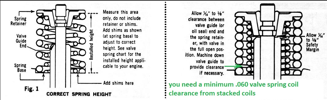
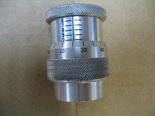
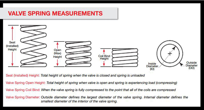
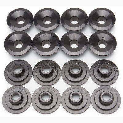
I also checked my coil bind values, springs are PAC 1218 Beehives with 7/32 beehive retainers and locks.
https://www.youtube.com/watch?time_continue=15&v=PruJ4FSmhP4
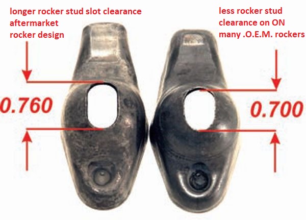
if youve ever wondered why the press in rock studs work loose and pull out of heads,
or why some less expensive rocker studs break, keep in mind the rocker and push rods,
are under hundreds of ft lbs of valve spring pressure and the rocker studs deflect significantly under load,
as the lifter rides up on the cam lobe and the valve spring deflects under load,
its really a miracle more rockers and rocker studs don,t snap off.
and the video, shows clearly why rocker stud girdles add considerable valve train stability
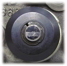
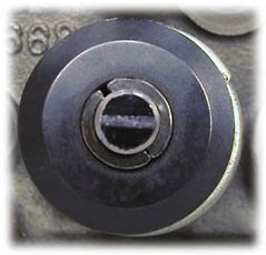
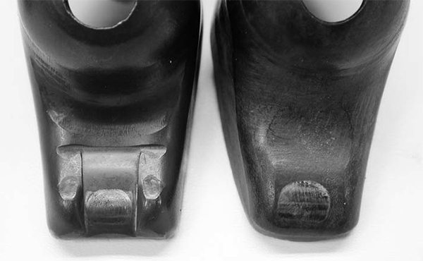
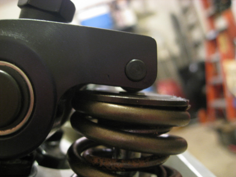
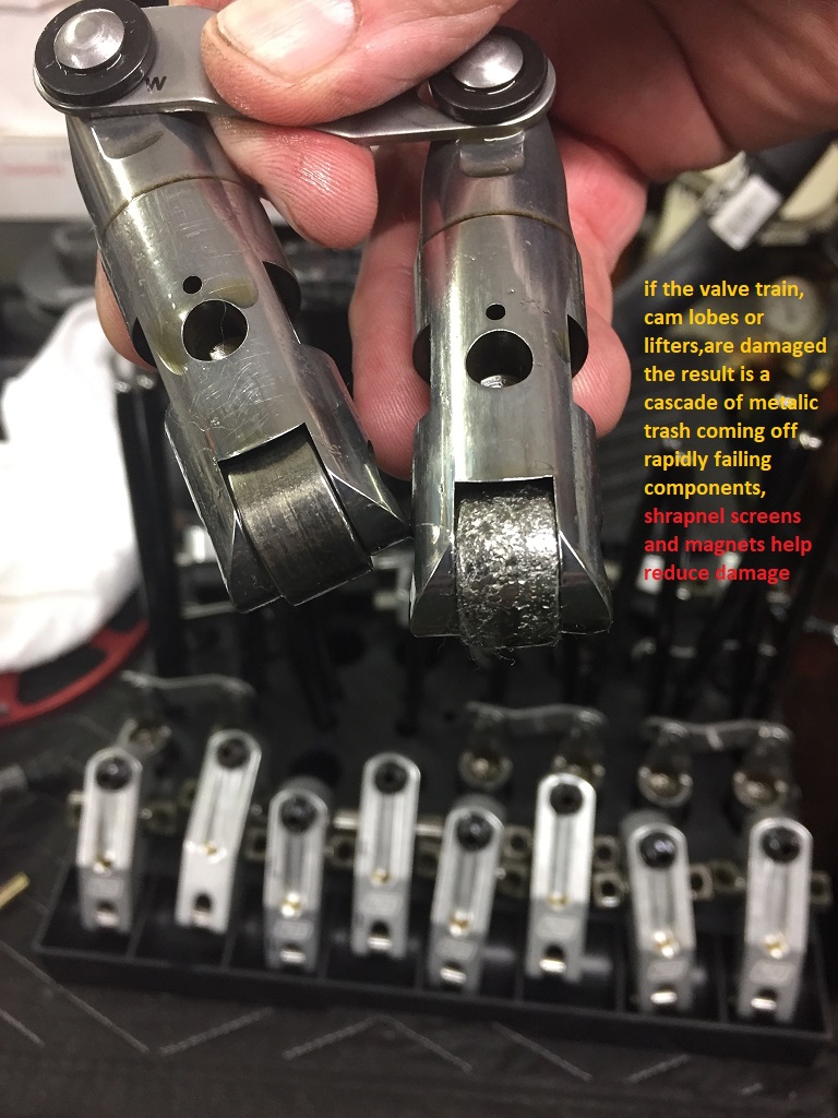
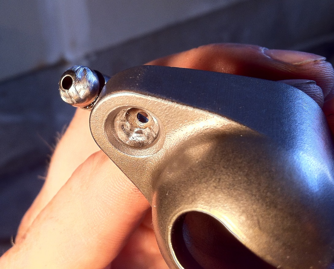
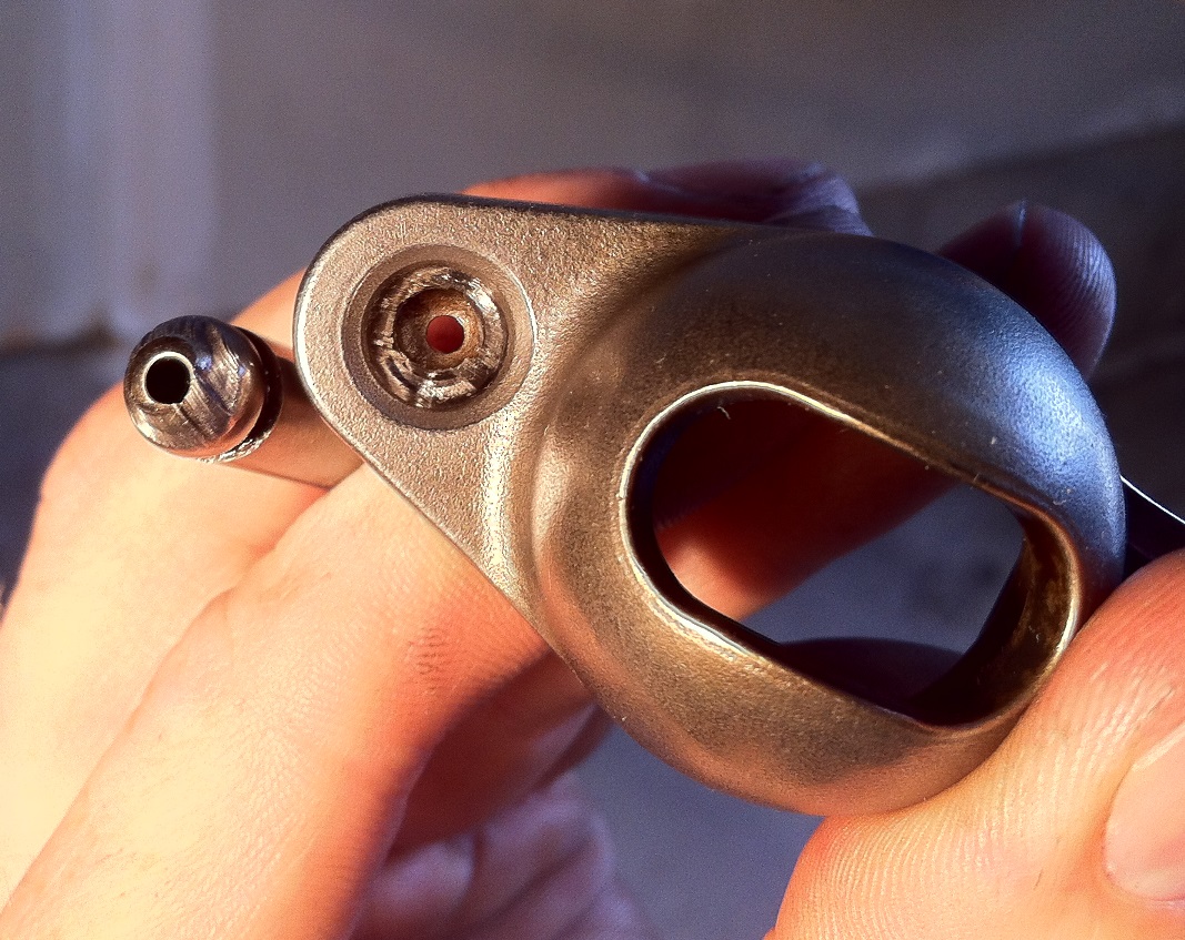
Took them off for inspection and found this.
its not horsepower, its the stress on the valve train, that makes a rocker stud girdle and its increased rigidity useful,
and thats more closely related to average stress levels, RPM and VALVE SPRING LOAD RATES
any time your occasionally exceeding 6000rpm or getting close too 330 lbs of open valve load rate Id strongly suggest screw in rocker studs
any time your intentionally exceeding 6000rpm and exceeding 350 lbs of open valve spring rate a rocker stud girdle might be a good idea.
and if your regularly exceeding 6500rpm and 400 lbs of open valve spring load rate its use is going to become almost mandatory
http://www.summitracing.com/parts/pro-66950

http://www.summitracing.com/parts/sum-141010
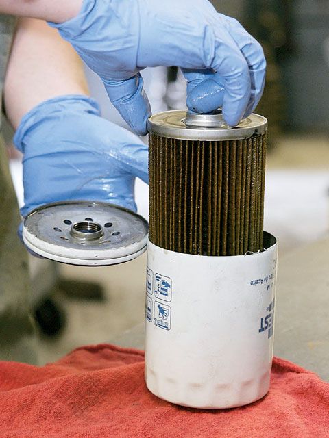
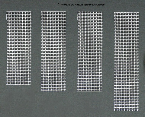
while I generally use stainless 6 or 8 mesh screens theres lots of options that will work just fine, just remember to keep the oil changed regularly or theres some potential for sludge to clog ANY size shrapnel screens

http://www.twpinc.com/twpinc/products/T ... 6T0350W36T
http://www.twpinc.com/twpinc/products/T ... 8S0280W36T
mor-25026.jpg

http://www.summitracing.com/parts/mor-25026?seid=srese1&gclid=COOf2IODscgCFZKAaQodHWoF1Q
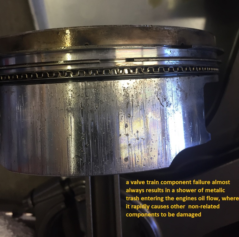
it should not take a great deal of imagination to see that a broken rocker, lifter or push-rod could dump metalic debris into an oil drain back port that wold rapidly result in increased internal engine damage as a result.
img_1047_2.jpg


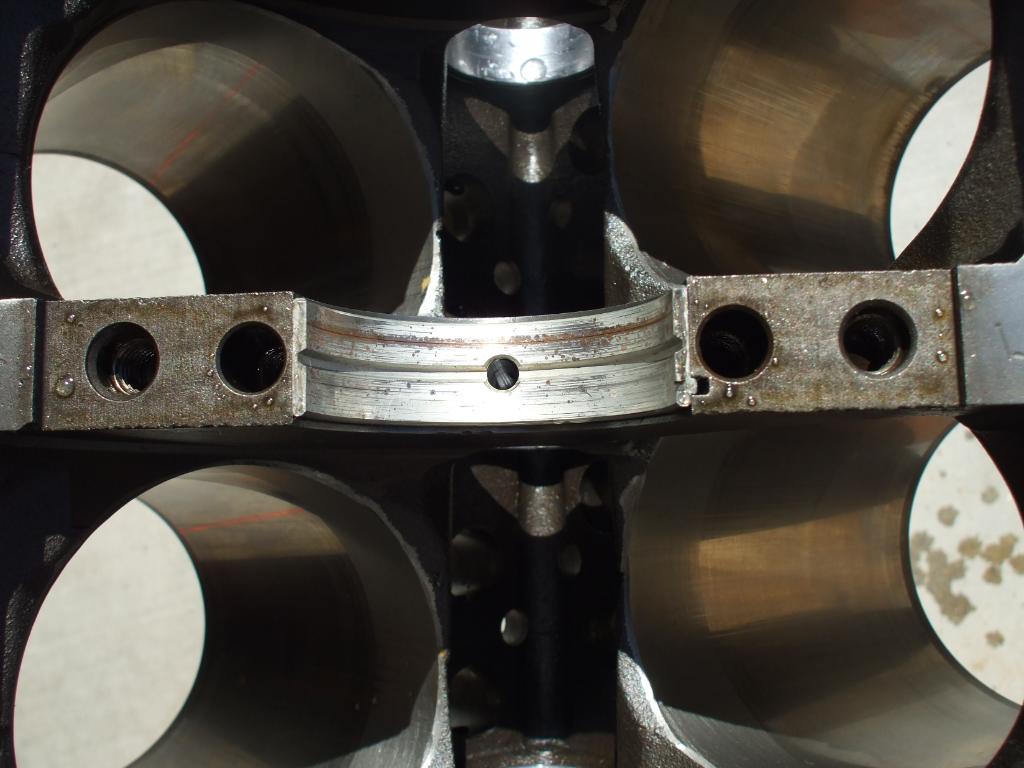
IVE typically used these magnets in an engine, one in the rear oil drain on each cylinder head, one near each lifter gallery drain and 4 in the oil pan sump
proper magnets trap metallic debris
SmCo Samarium Cobalt Disc Magnets
http://www.magnet4less.com/
many magnets lose their magnetic pull if heated to 200F
these below won,t

proper magnets trap metallic debris

SmCo Samarium Cobalt Disc Magnets
http://www.magnet4less.com/
enginemagn.jpg


http://www.magnet4less.com/product_...ucts_id=254&osCsid=ckl4nevgdrmireotnegg7jcf36

http://www.magnet4sale.com/smco-magnets-dia-1x3-8-samarium-cobalt-magnets-608-f-temperature/

Samarium Cobalt MAGNETS HELP
http://www.magnet4sale.com/smco-disk-magnet-dia-1x1-4-samarium-cobalt-magnets-608-f-temperature/
magnets are ceramic and glass hard, don,t try to drill or grind them, as they can shatter
tippattern.jpg

valvetrd.png

prpr1.jpg
images

prpr2.jpg

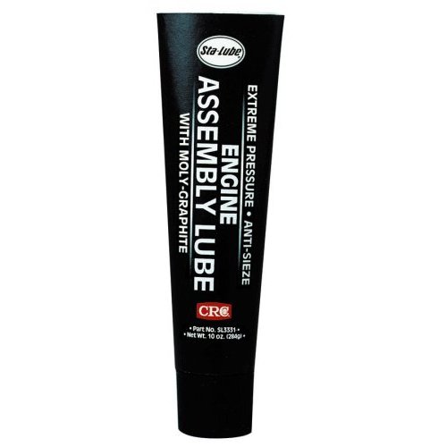
Even with roller valve train there is a break in period where the metals have to "mate". on flat tappet valve trains and non-roller rocker valve trains use of a good moly assembly lube is critical, Break in oils and assembly lubes have high pressure additives to help protect these new surfaces while this "mating" is taking place. Regular motor oil does not, always have the required additives or enough of them. thus using a good moly based assembly lube on lifters and bearings helps reduce wear , on roller rockers and roller lifter a mix of 50% assembly lube and 50% MARVEL MYSTERY OIL, thins this moly mix viscosity allowing it to penetrate roller bearings far faster

http://garage.grumpysperformance.com/index.php?threads/freeing-up-sticky-hydraulic-lifters.15582/

https://www.youtube.com/watch?v=o5is9BsH5OU


http://engineprofessional.com/articles/EPQ409_58-62.pdf


molysp3.JPG

molysp2.JPG

molysp1.JPG

pre-spraying all bearing and valve train components with a moly based spray, helps embed micro moly lubricants in the metallic surface micro fissures , a good paste lube like cranes assembly lube over the spray surface helps insure a good lubricant surface coating, that is far stronger than just the ZINC and PHOSPHATES in oil
crn-99004.jpg

zddp.jpg


crcassembly.jpg

marvel.jpg

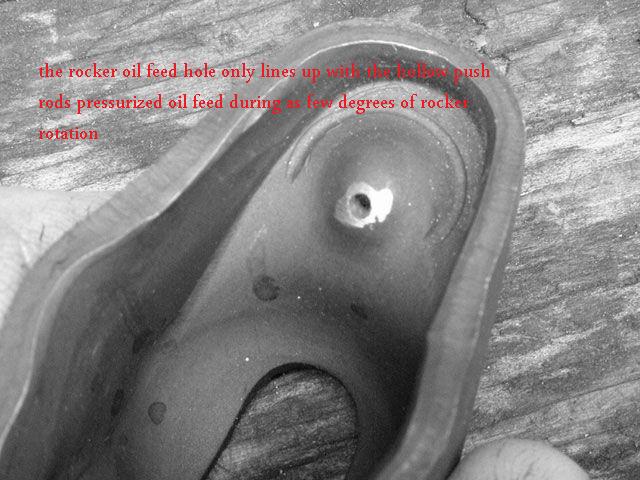
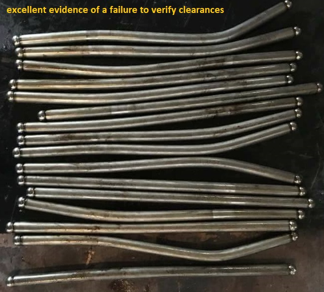
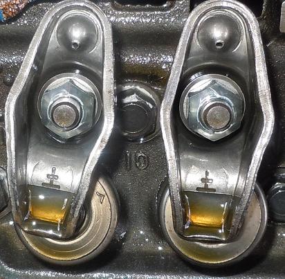
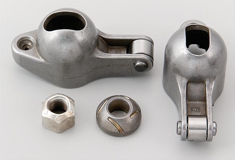
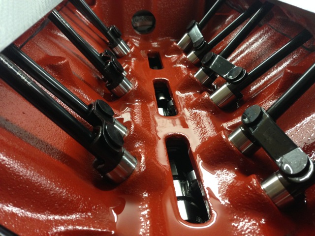
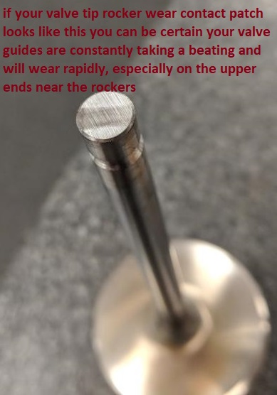
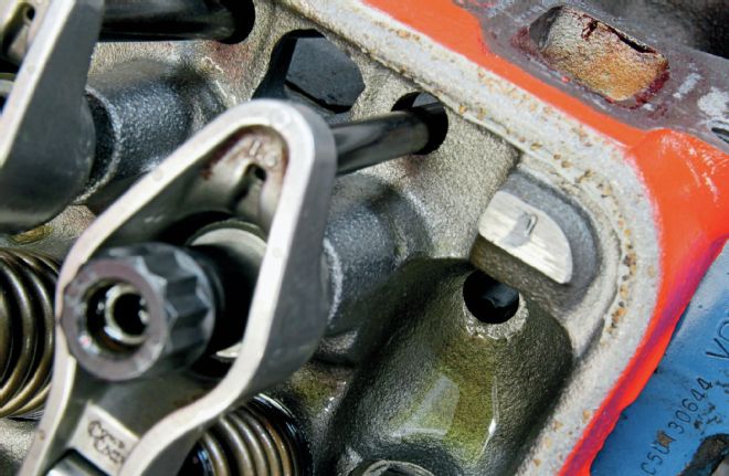
look at the tip of the rocker and push rod , all the wear is in the same sweep direction,across the tip,if the push-rod clearance was too great they would tend to bounce and rotate on contact, the consistent wear tends to indicate the lash clearance or pre-load is too tight or your not getting nearly enough oil flow,on the contact point between the rocker and push rod tips, on that roller lifter cam, and there's not enough oil flow thru the contact wear points , so Id suggest cleaning out any crap that might be inside the push rods and adjusting the valve pre-load so there's oil flowing at idle from the rockers, failure to have consistent oil flow or having the wrong clearances could easily result in rapid wear from the wrong clearances or geometry or lack of oil flow , especially if the push rods bind in the guide plates or cylinder heads guide slots, thus reducing the push rods tendency to move , Id sure inspect the whole length of the push rod and expect to see wear indications where the push rod goes thru the guide plates or head slots

BTW wear like that indicates you have micro metallic crap in the oil (its un-avoidable) if you have MAGNETS they probably trapped and held the vast majority, but you might want to consider changing your oil and filter and checking your oil filter internally, and yes I know your thinking of just replacing the push-rods and reusing the rockers due to cost issues, but if you do it will result in a repeat due to the worn surfaces, so replace both the rockers and push rods and this time verify the clearances and rocker geometry much more carefully and adjust the rockers so they have minimal pre-load.
now theres a small chance you could successfully pollish out the rockers push rod cup area with a dremel tool and the correct size and shape hard grinding stones to a point they could be re-used but Id strongly suggest buying new rockers is the safer route

Ive never had an issue re-using old push rods on new roller rockers with a good dose of moly cam lube on the tips , AS LONG AS the tips looked like they were in decent condition and not obviously worn,after, they passed a close inspection before they were used, OBVIOUSLY THE PICTURES ABOVE ARE PUSH RODS THAT GO IN THE DUMPSTER, most good brand name aluminum or steel roller rockers have pressed in hardened steel push rod seats that are far less likely to wear than the tips of the push rods.
pushrodbna.jpg

rocknut.png


heres a bit of useful related push rod length info
Big Block Chevy, Standard Length Big Block Intake 3/8" / .080" 8.275"
295-7941-8 Big Block Chevy, Standard Length Big Block Exhaust 3/8" / .080" 9.250"
295-7969-8 Big Block Chevy, Standard Big Block +.100" Long Intake 3/8" / .080" 8.375"
295-7979-8 Big Block Chevy, Standard Big Block +.100" Long Exhaust 3/8" / .080" 9.350"
295-7951-8 Big Block Chevy, Standard Length Big Block Tall Deck Intake 3/8" / .080" 8.675"
295-7961-8 Big Block Chevy, Standard Length Big Block Tall Deck Exhaust 3/8" / .080" 9.650"
295-7800 V8 396-454 Retro Fit Pushrod Set, Intake & Exhaust, 1965-Present
3/8" / .080"
3/8" / .080" 7.725 Int.
8.675 Exh
295-7913-16 Small Block Chevy, Standard Length Small Block Chevy 3/8" / .080" 7.800"
295-7984-16 Small Block Chevy, +.100" Long 3/8" / .080" 7.900"
295-7934-16 Big Block Ford, Standard Length Ford `72-'78 429-460 3/8" / .080" 8.550"
295-7951-16 Big Block Ford, Standard Length Ford `69-'71 429-460 3/8" / .080" 8.675"
295-7582-16 Oldsmobile, Std Length 455 5/16" 9.550"
cranerrco.jpg

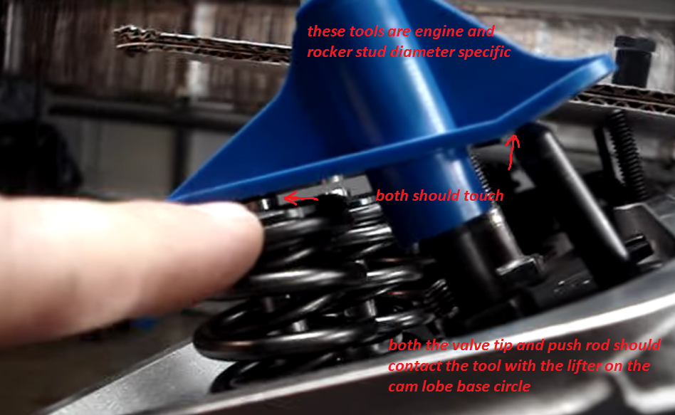
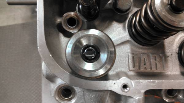
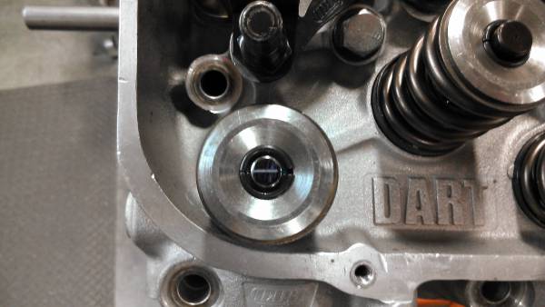
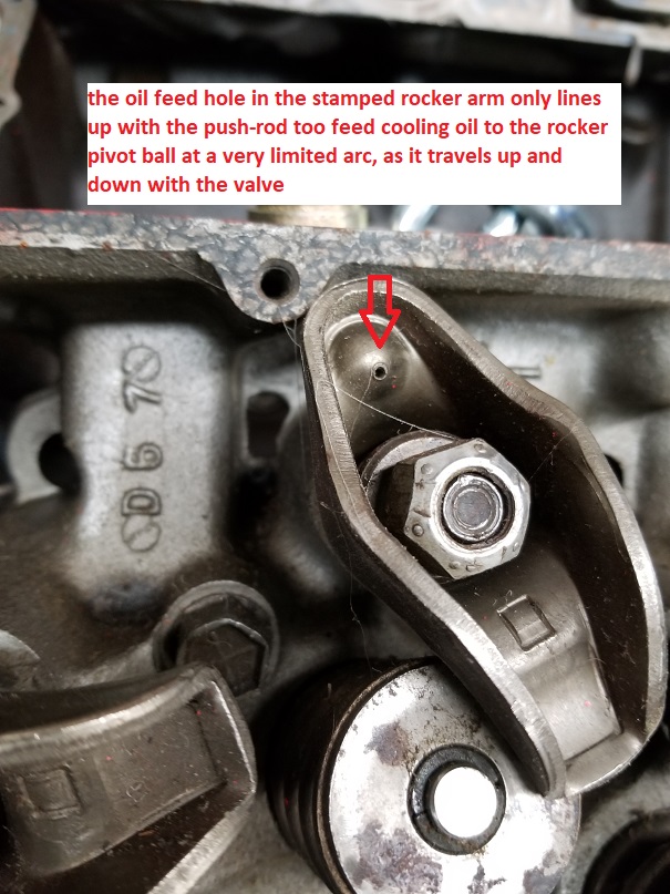
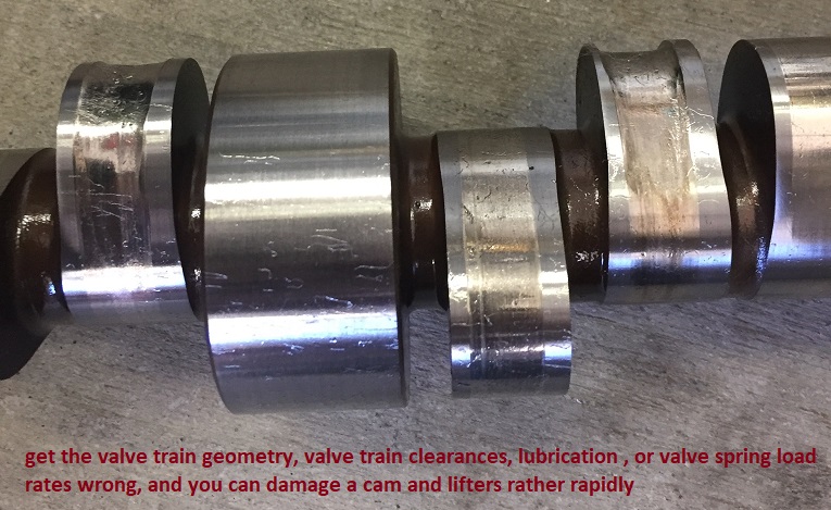
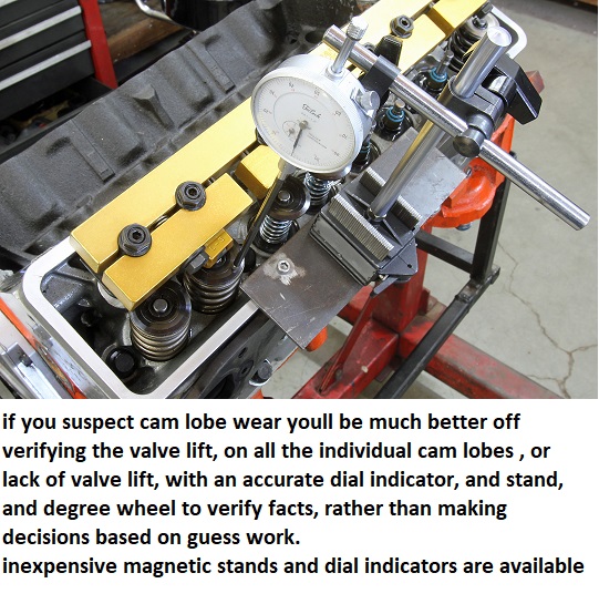
OBVIOUSLY that assumes you have no valve train clearance issues, binding or geometry or lubrication issues, and you set the lash or lifter pre-load on the valve train correctly and use the correct oil, and it certainly would help any engines durability to have provisions for adequate valve train oiling and a bit extra valve train cooling can be helpful on an engine designed for higher rpm use.
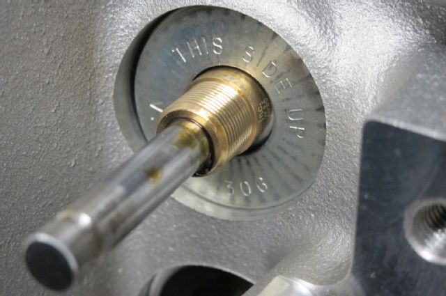
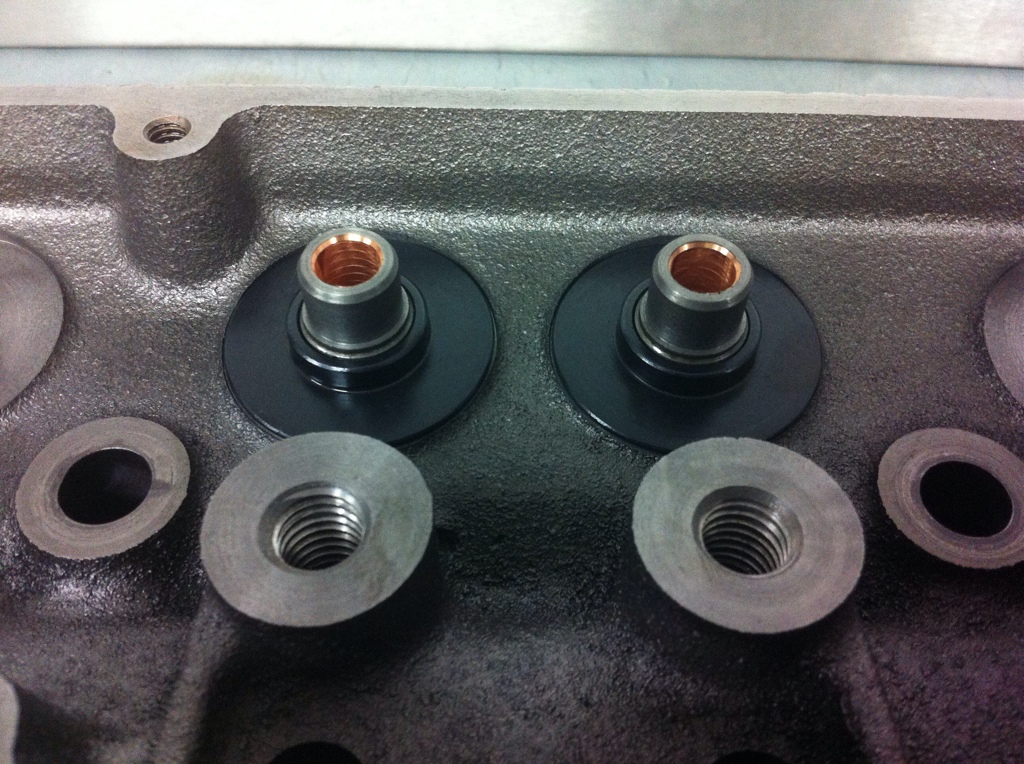
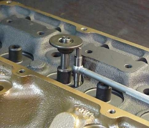
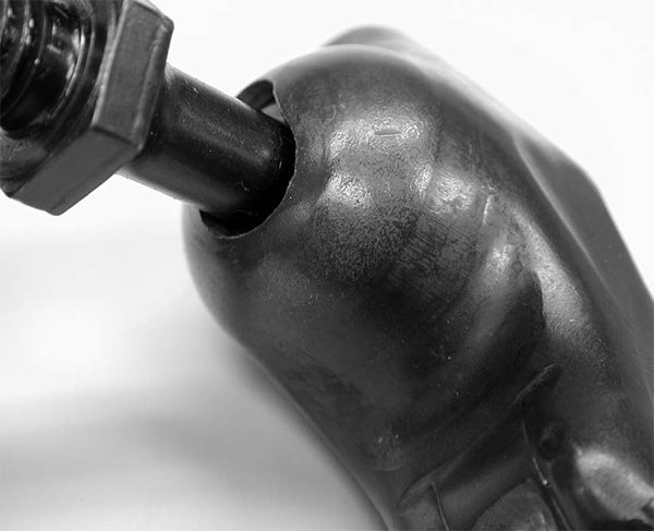
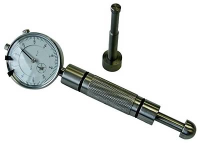
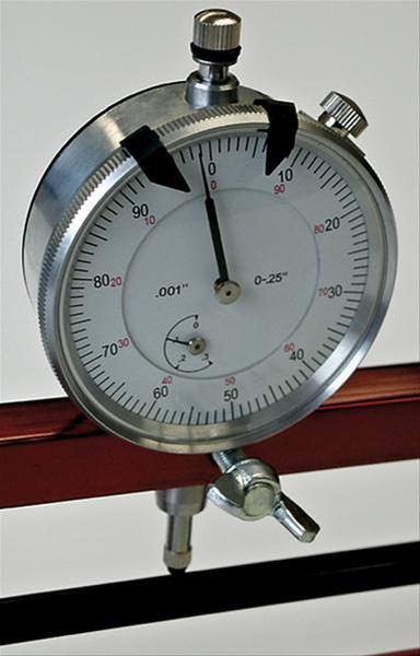
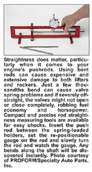
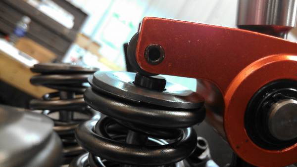
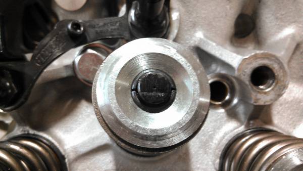
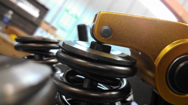
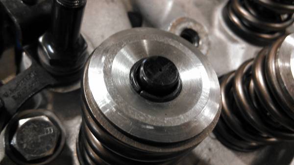
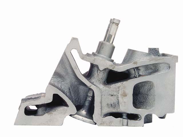
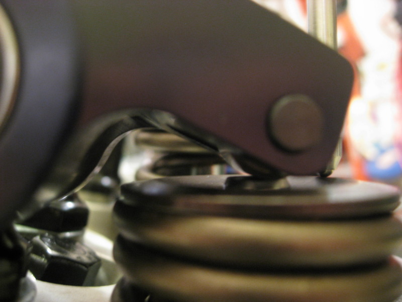
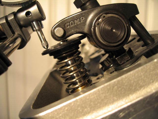
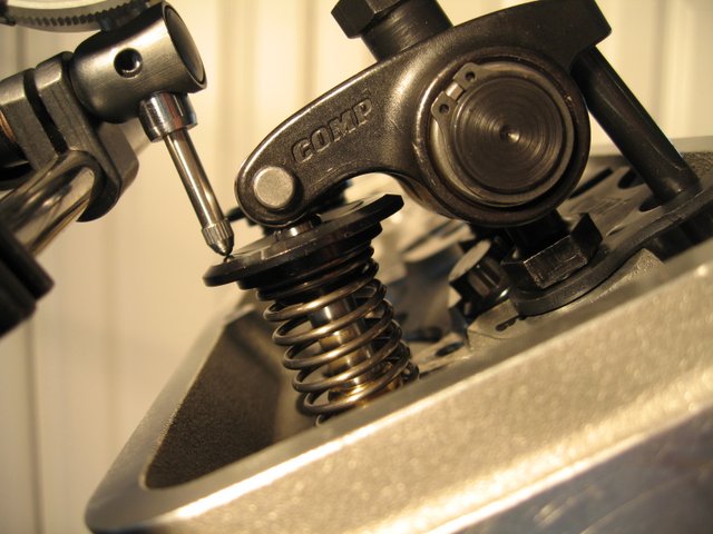
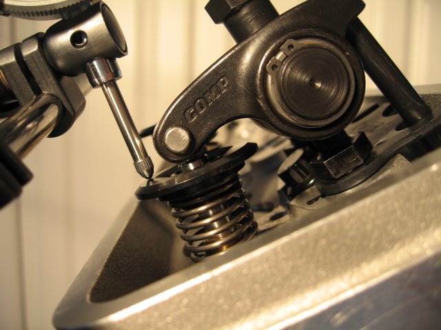
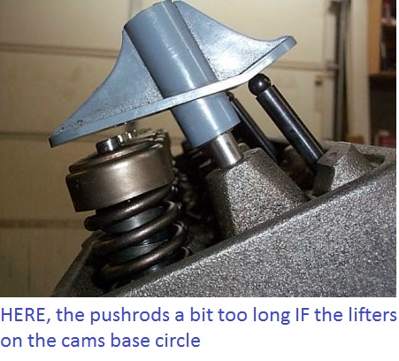
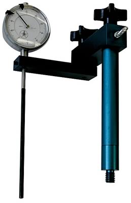
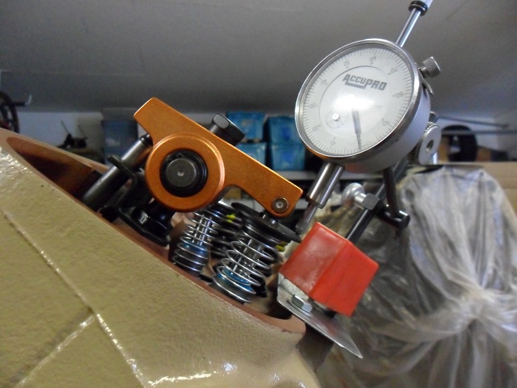
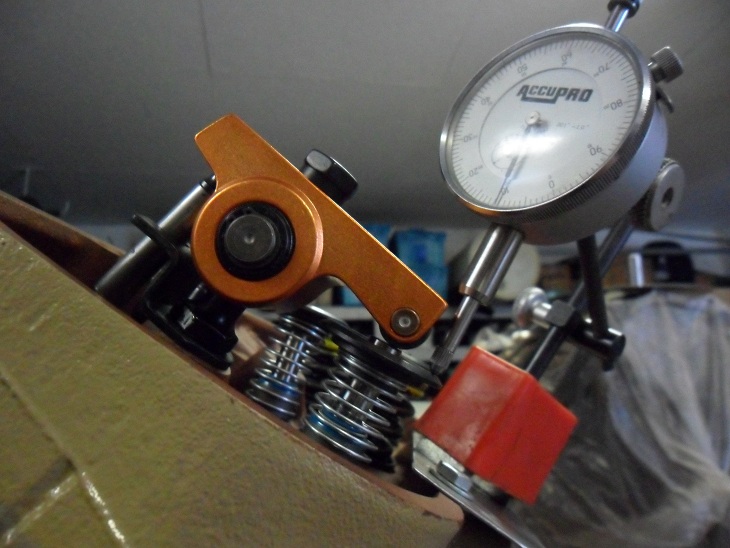
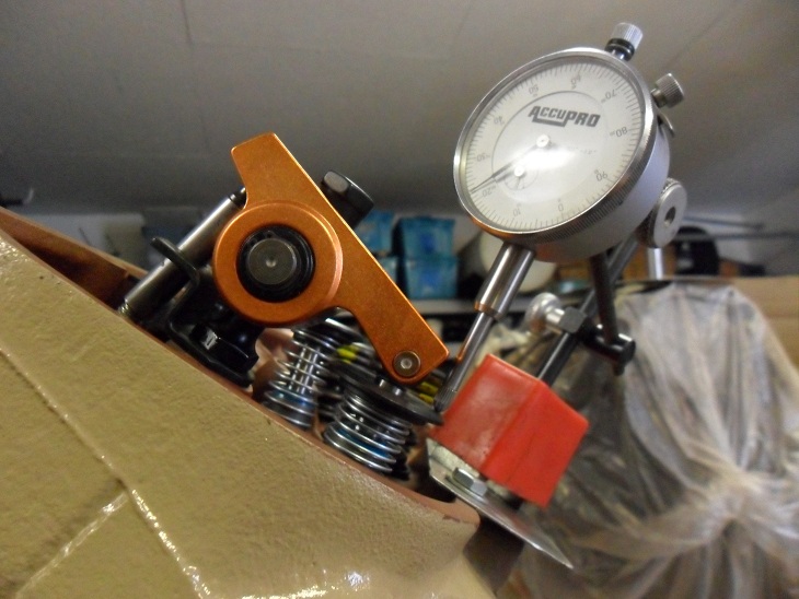
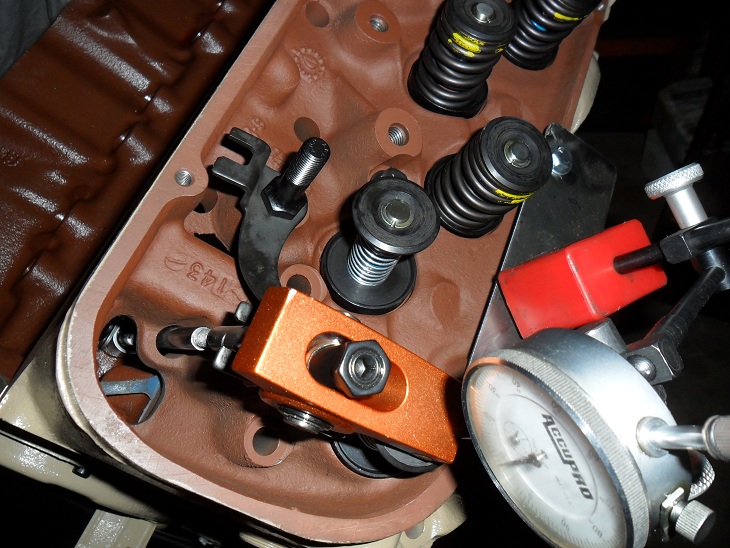
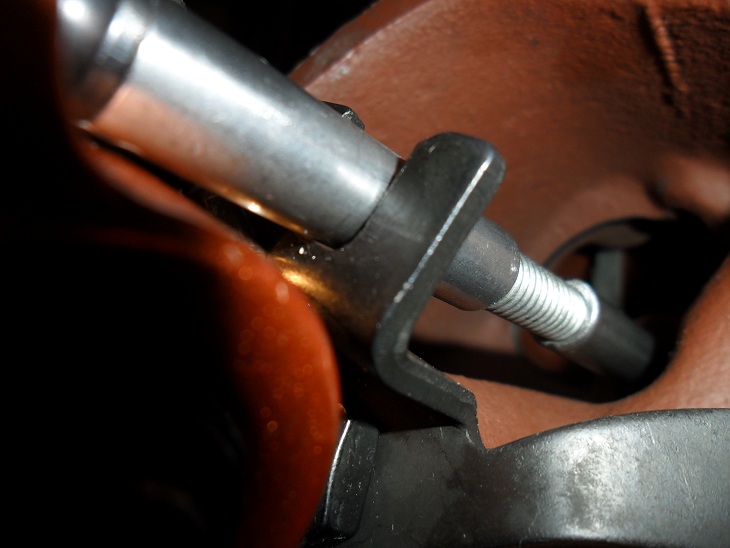
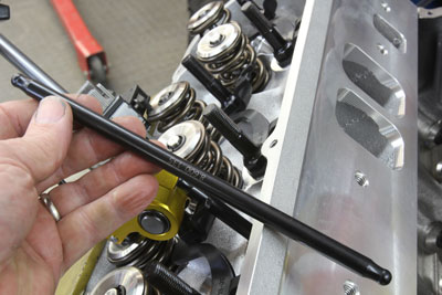
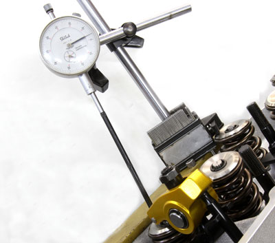
heres a really interesting series of pictures taken when a guy was checking the correct push rod length and rocker geometry on a big block chevy, he noticed the dial indicator readings were not consistent, the cause was traced to the push rod guide plates contacting the push rod and binding the push rod making the tip move across the rocker push rod pivot cup. if the engine was run like that with the push rod binding in the guide plate parts failure was certain to occur in a reasonably short time

https://www.hotrod.com/articles/ctrp-0805-valvetrain-dynamics/

http://www.summitracing.com/parts/pro-66830/overview/

pro-66830_cp.jpg

https://www.youtube.com/watch?time_continue=5&v=o5is9BsH5OU

liftc1f.jpg

worn5.jpg


https://www.harborfreight.com/multipositional-magnetic-base-with-fine-adjustment-5645.html


bv93fans.jpg

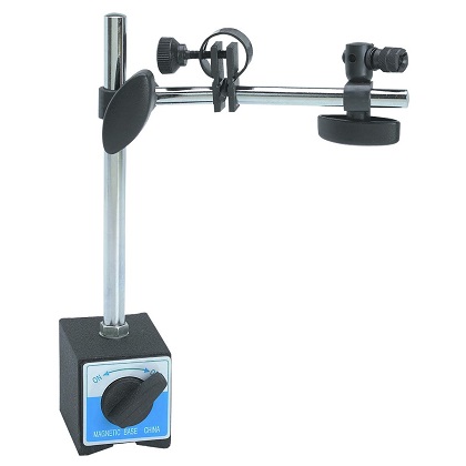
https://www.harborfreight.com/catalogsearch/result/index/?dir=asc&order=EAScore,f,EAFeatured+Weight,f,Sale+Rank,f&q=indicator+stand

Rocker1closed.jpg


Rocker2mid-lift2.jpg


Rocker3fulllift.jpg


Rocker5.jpg


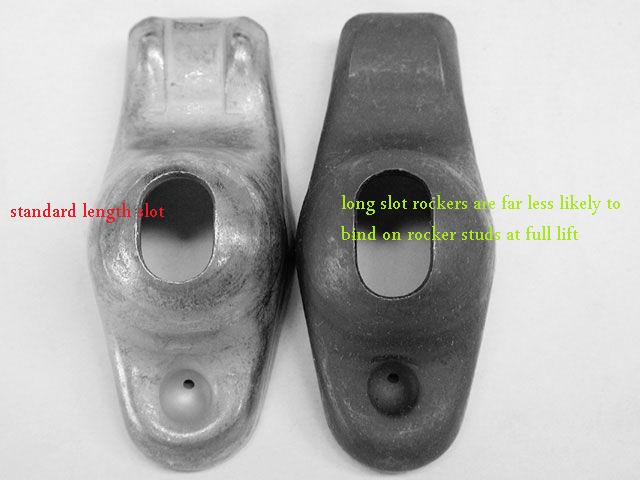
If your thinking you can swap to the 1.6:1 rockers without checking clearances carefully, ...probably not, your certainly going to need to check and verify clearances , and yeah, youll find a dozen guys that say they did it with zero problems......many could also tell you that in a few months they experienced a cam lobe /lifter or rocker failure as the push rod binding in even only part of the rockers arc, tends to cause excessive wear on the valve train, it might take some time but it will result in component failure over time if parts can,t move freely as designed.

sguide_plate.jpg

pushrodbind.jpg


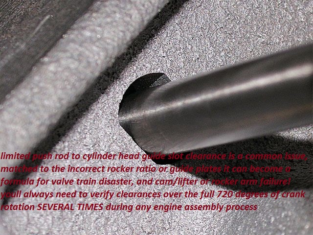
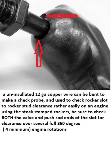
youll want too use a .060 clearance too the push rod to cylinder head slot clearance CHECKED CAREFULLY OVER THE FULL ARC OF THE ROCKER TRAVEL FOR A FULL TWO ENGINE ROTATIONS
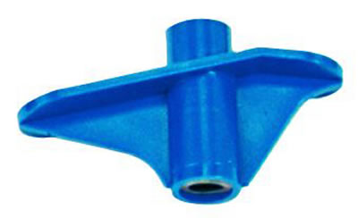
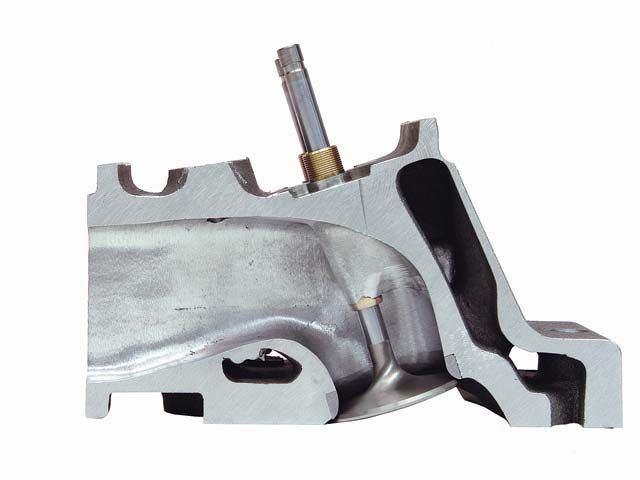
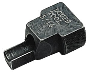
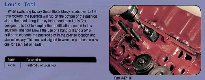
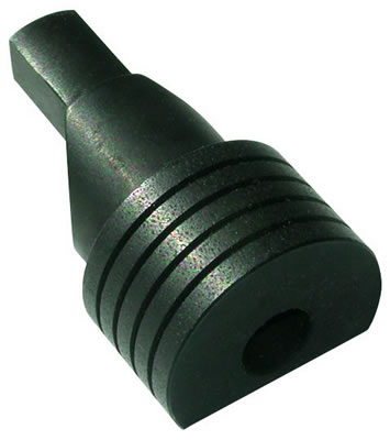
if you need a LOUIS TOOL to lengthen the slots in the cylinder head I generally lay a section of plastic wrap in the lifter gallery and be sure to place two magnets on the blocks lifter gallery wall, to hold the thin plastic wrap in place firmly, below the cylinder head while drilling to catch the metalic debris the drill will generally produce, between the plastic sheat and the magnets youll generally catch 100% of the trash the drill generates

24947101.jpg


STUD-12.jpg

louis2.png

louis1.png


pro-66485_w.jpg


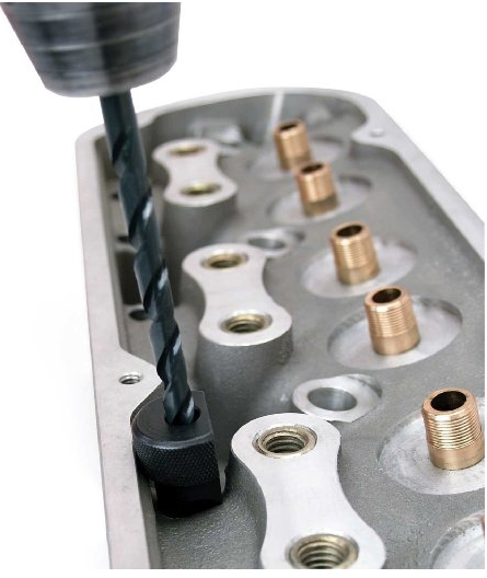
btw place a magnet like this under each pushrod slot to catch the drill chips from iron heads
louist.jpg

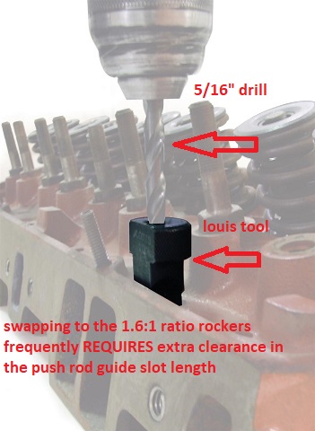
These Proform pushrod slotting tools are designed to elongate the pushrod slot in the cylinder head. They will make room for higher ratio rocker arms. Use these tools with a drill and a 5/16 in. drill bit to elongate the pushrod slot.
RockerGeometry.jpg

http://garage.grumpysperformance.co...o-rockers-and-the-pushrods-rub.198/#post-3033
http://garage.grumpysperformance.co...swap-in-1-6-1-ratio-rockers.10671/#post-46039
http://garage.grumpysperformance.co...e-train-clearances-and-problems.528/#post-664
pushrodbind.jpg


REMEMBER TO CAREFULLY CHECK THE PUSH ROD TOO CYLINDER HEAD GUIDE SLOT AND CYLINDER HEAD CASTING CLEARANCES,IF THE PUSH ROD BINDS IT MAY CAUSE A LOSS OF OIL FLOW THROUGH THE PUSH ROD, FROM LIFTER TOO ROCKER OR THE LIFTER TO WEAR RAPIDLY

checking all valve train clearance issues in mandatory
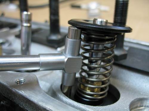
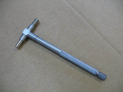
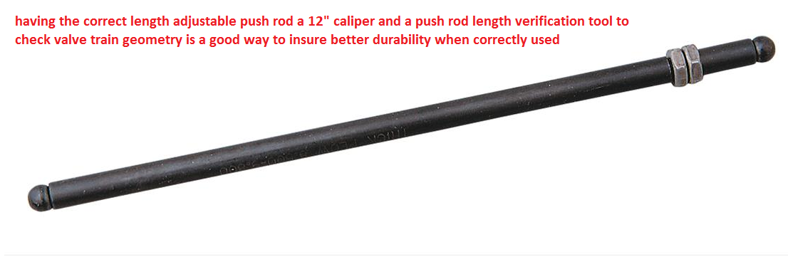
notice the adjustable length checking push rod used below and the push rod binding in the guide plates
Rocker4.jpg

I can,t even begin to tell you how many times I see guys slap a new cam in an engine and not carefully verify all the rocker geometry and clearances, and it sure does not take a great deal of valve train binding to cause serious problems

A Simple Test for Valvetrain Deflection

Engine building is all about attending to the details. The professionals know that all is not as it seems when it comes to something as simple as valve lift. We had an opportunity to discuss this with Ben Strader, president of EFI University, where he and his staff not only teach engine building and EFI tuning, but also apply what they learn on the dyno.

5f63804df8b0ad97e149da766f912363

By

Trend Performance
on

Jun 1, 2018
001-trend-valvetrain-stiffness-test.jpg


Engine building is all about attending to the details. The professionals know that all is not as it seems when it comes to something as simple as valve lift. We had an opportunity to discuss this with Ben Strader, president of EFI University, where he and his staff not only teach engine building and EFI tuning, but also apply what they learn on the dyno. Amid a day-long discussion concerning engine building, Strader mentioned that one of the best ways to evaluate the quality of a valvetrain is to rate it based on stiffness.

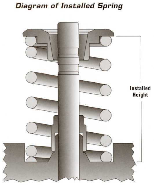
Valvetrains are subject to essentially two different ways load is applied, generally referred to as static and dynamic. Static load is simply the load you can measure with a spring load tester and then multiplied by the rocker ratio. For example, if we have 500 pounds of spring load at maximum valve lift and a rocker ratio of 1.5:1, the rocker arm, rocker stud, pushrod, and lifter are exposed to a static load of 750 pounds (500 x 1.5 = 750 lbs) of force.

002-trend-valvetrain-stiffness-test.jpg

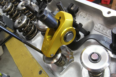
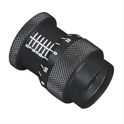
We started this exercise by checking maximum valve lift on the exhaust valve of this 540ci big-block Chevy using a light-duty checking spring. The maximum lift measured 0.744-inch.

The second type is called dynamic load which accounts for the forces applied to the valvetrain while accelerating and decelerating the valve at various engine speeds. These dynamic forces are incredibly high and impart loads much greater than what we can measure statically since these components are accelerating at incredible speeds even at engine speeds of 6,000 to 7,000 rpm. Of course, the load increases with each jump in engine speed.

One way we can verify or measure the effective stiffness of the valvetrain is to perform a stiffness test. The usefulness of this test is in its simplicity. The process involves comparing maximum valve lift with a checking spring against the lift created using the actual valve spring. The average enthusiasts might consider this to be a waste of effort because the numbers should be the same. But all it takes is a simple test like this on a performance engine to realize that there’s some bending happening in the valvetrain.
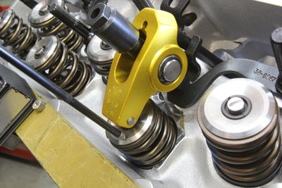
Let’s use a real-world example to show how this works. We started with a big-block Chevy by measuring maximum valve lift on the exhaust side by using a checking spring instead of the actual valve spring.

The test used a Crane 1.7:1 aluminum roller rocker, an 0.080-inch wall thickness, 3/8-inch diameter Trend pushrod, and a mechanical roller lifter. Using the checking spring, we measured maximum lift on the exhaust side at 0.746-inch. We then switched to a cylinder already loaded with the intended valve spring at its proper installed height. This spring checked on our Longacre load tester with 235 pounds on the seat.

We then repeated the lift test except with the dual spring in place which revealed a peak lift of 0.710-inch. We ran through this test three times to ensure this number was correct. This meant that by adding spring pressure, this typical big-block rocker stud combination had managed to lose 0.036-inch of valve lift. Strader offered a list of potential sources where this bending could originate that we’ve included.

003-trend-valvetrain-stiffness-test.jpg

Next, we checked the max lift on an adjacent valve with the actual valve spring using the same lifter, pushrod, and rocker arm. We were surprised to find that with 600 pounds of open load, the max lift dropped to 0.710-inch. This resulted in a deflection of 0.034-inch.

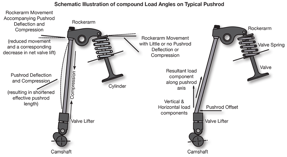
Our first thought was to test for pushrod deflection. We measured the valve spring load at 0.710-inch of valve lift and came up with 610 pounds. We will assume a 1.7:1 rocker ratio. We can also assume the actual ratio changes based on the position of the rocker over the valve at max lift. The rocker ratio multiplies the load that the pushrod sees – which means the load on the pushrod is 610 x 1.7 = 1,037 pounds. This is the static load and does not take into account the acceleration rates imposed on the system that could easily achieve g-loads of 250 to 300 g’s. But that’s a story for another time.

While it’s likely that the pushrod will deflect slightly with this much load because it is not perfectly vertical, this may not the only source of deflection. Because this is a stud-mounted rocker arm system, it’s entirely possible that even with high quality 7/16-inch rocker studs that they could also deflect. This is where a stud girdle would be of further benefit. The ideal solution would be the addition of a quality shaft rocker system such as one from Jesel or T&D but by this time, unless your combination calls for spring loads that approach 1,000 pounds open, the return on the investment might not be strong enough.

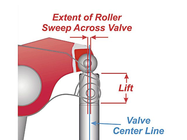
The rocker arm is another place where the system could be deflecting. Aluminum is the most often-used material for rockers in an effort to reduce weight, but this comes at a price. While lighter, aluminum is far less rigid when compared to steel. However, in this case, we tested both aluminum and steel versions and recorded no difference in maximum lift. Of much greater concern is the effect of pushrod length on the entire lift curve. We did not perform a refined pushrod length test on this engine to determine the ideal length. If pushrod length is not ideal, this will affect the overall rocker ratio by changing the distance the rocker travels across the tip of the valve. This might be cause for a separate story on the effect of pushrod length on lift.

All of this effort to reduce deflection focuses mainly on improving the overall stiffness of the valvetrain. Strader says that he learned a simple way to calculate the stiffness that can then be used to evaluate different valvetrains from a noted cam designer. His source recommended simply dividing the peak valve spring load by the amount of the deflection. In our case, this was a spring load of 610 pounds divided by the deflection of 0.036-inch. This generates a stiffness rating of 16,944 pounds-per-inch. Note this is a load rating, not a pressure rating so the load is expressed in pounds-per-inch.

Strader’s source also created a rating system based on this load number and considers 20,000 pounds/inch and above to be acceptable. If your system generates a rating of 25,000 pounds/inch or more –consider your efforts justly rewarded.

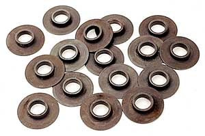
As you can see, this big-block is fairly close to that 20,000 lbs/in threshold stiffness number. The variables are both the spring load and the amount of deflection. Achieving a higher number could be attained by either reducing the spring load – which most engine builders don’t prefer – or to increase the stiffness by reducing the deflection. All this information also only relates to static testing and only the relative stiffness has an impact on the dynamic part of this equation. In reference to that, reducing the weight with a tool steel or titanium retainer, for example, is one place where this has little impact on stiffness yet would drastically reduce the dynamic load the spring is forced to deal with at high rpm.

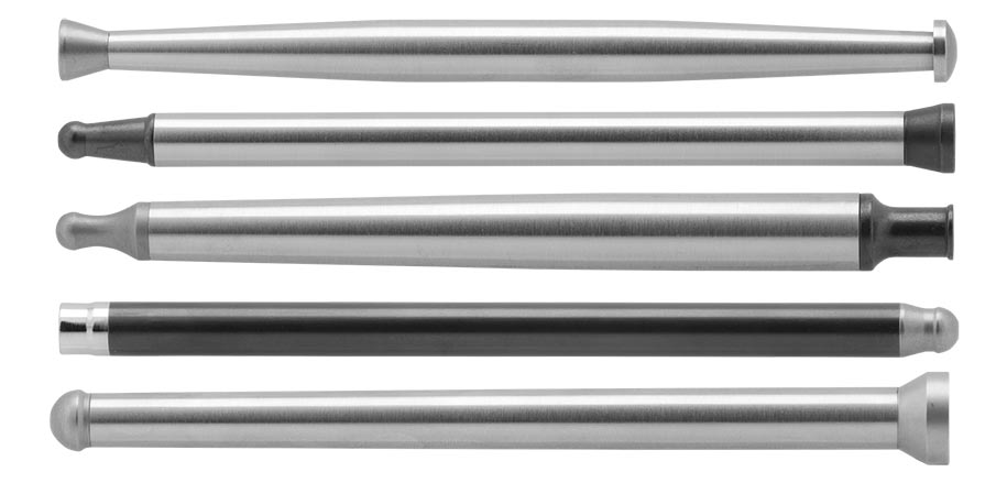
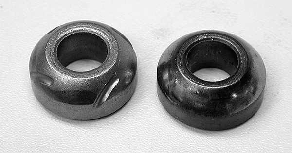
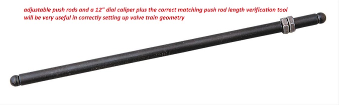
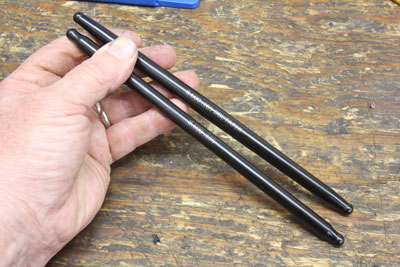
This brings us back to our original test. We decided this engine’s low-hanging fruit might be the 3/8-inch, 0.080-inch wall thickness pushrods. So we ordered a set of Trend pushrods in the same 3/8-inch diameter and length but with a thicker, 0.135-inch wall that is rated to be 37 percent stiffer.

004-trend-valvetrain-stiffness-test.jpg

We were using a typical 3/8-inch, 0.080-inch wall thickness pushrod for this test. For comparison, we decided to do a simple strength upgrade by moving to a Trend 3/8-inch pushrod with a stronger, 0.135-inch wall thickness. Externally, the pushrods appear the same although the stronger pushrod is slightly heavier. We measured an 8.600, 0.135-inch wall thickness pushrod at 109 grams vs. an 0.080-inch wall pushrod of the same length that weighs 82 grams. That’s a 27 gram difference that equals a 33 percentage weight increase.

Plugging the thicker-wall pushrod into our 540ci test engine immediately improved the valve lift under actual spring load from 0.710 to 0.718-inch. That’s an instant valve lift improvement of 0.008-inch. We were hoping for more, but considering the ease with which this gain was achieved, it’s hard to argue the improvement. This also required recalculating the stiffness rating. There was only a slight change in the spring load, with the 0.718-inch lift working against 619 pounds. Calculating the rating then produced a stiffness rating of 22,107 lbs/in which is a significant improvement over the original 16,944 lbs/in number. Doing the math, that’s a 30 percent improvement in valvetrain stiffness just by changing to a slightly thicker wall pushrod! That’s the most amazing part of what would appear to be an otherwise minor change in deflection.

To take this evaluation one step further, we tested a 7/16- to 3/8-inch fully tapered pushrod in that same exhaust location using the same length pushrod. Running through the lift curve once more, we saw only a very slight improvement of 0.002-inch of valve lift over the 0.135-inch wall thickness pushrod. So in this case, there was little to be gained. In a system with a maximum spring load of over 800 lbs/in, this is where the larger tapered pushrod would see more improvement.

005-trend-valvetrain-stiffness-test.jpg

Adding the new Trend 0.135-inch wall pushrod improved maximum valve lift by reducing pushrod deflection. Just adding the pushrods improved valve lift by 0.008-inch. That’s a 25 percent reduction in deflection! You won’t find an easier way to improve valvetrain stability.

There’s much more to this story but there’s enough here to keep you busy checking valvetrain deflection on your own engine. We’d like to thank Ben Strader and EFI University for his willingness to share this information. This is just one small part of what his company offers in its Competition Engine Development (CED) course, so if this little snippet of information intrigues you, there’s much more to learn. You can find details on the CED course at efi101.com.

Sources of Valvetrain Deflection


    • Rocker Stud Deflection
    • Pushrod Deflection
    • Rocker arm Deflection
    • Rocker Travel Across Valve Tip
    • Length of Pushrod
    • Lifter Bore Clearance
    • Pushrod Angle
    • Cam Core Diameter
This article was sponsored by Trend Performance. For more information, please visit our website at www.trendperform.com

https://www.ebay.com/i/402584062207...1291&msclkid=d17e7155654a1a20769a115a09f43c68


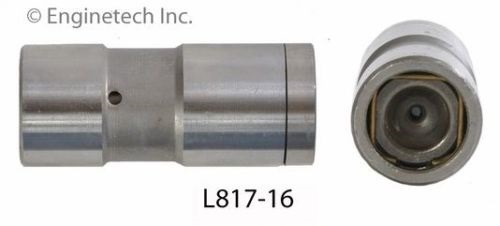
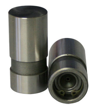
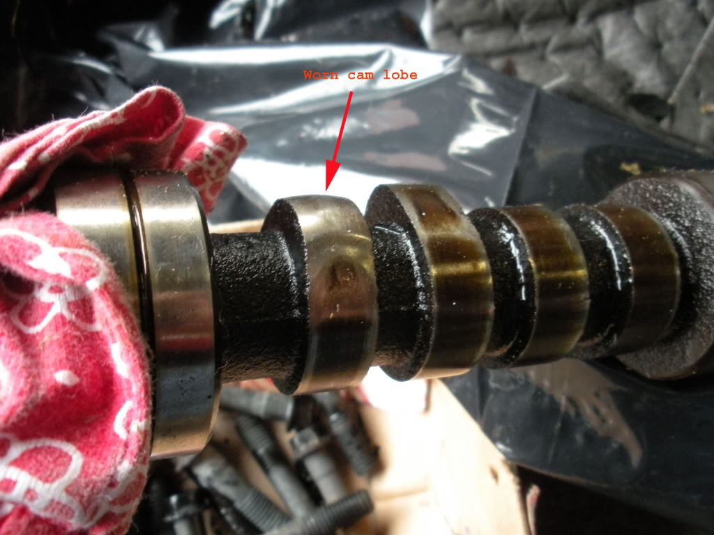
if the lifter base is well worn you can bet the farm the cam lobe is most likely also worn, and you'll need a lifter removal tool to pull the damage lifters up out through the blocks lifter bores

https://www.ebay.com/i/402584062207...1291&msclkid=d17e7155654a1a20769a115a09f43c68


s-l640.jpg

if the lifters are very badly damaged, it may be best to remove the push rods , use strong magnets to hold the lifters in place and remove the cam, then slide a section of pvc pipe with the upper half removed and let each individual lifter fall into the pipe and be removed one at a time and be removed rather than risk damaging the lifter bore walls, dragging the damaged lifters out through the blocks lifter bores
51CL6OmQO0L._AC_SL1300_.jpg

https://www.amazon.com/Player-Supreme-Golf-Tubes-Dividers/dp/B007BCW7E2/ref=sr_1_5?adgrpid=1343603775697452&dchild=1&hvadid=83975307164276&hvbmt=bp&hvdev=c&hvlocphy=45536&hvnetw=o&hvqmt=p&hvtargid=kwd-83975585067557:loc-190&hydadcr=6896_10422387&keywords=golf+club+tubes+for+golf+bag&qid=1614444214&sr=8-5&tag=mh0b-20
the thin plastic golf club bag tube organizers are almost ideal,
they are available in 1.25", 1.5" and 2" diameters
as they are easy to modify for retrieving lifters from the cam journals, as the golf bag organizer tubs are stiff but east to modify and cut if you need to retrieve lifters by dropping them into the cam journal area


READ THRU THE LINKS
http://www.airflowresearch.com/car-craft-nov-2014-pushrods.php


http://garage.grumpysperformance.co...g-block-pushrod-guide-plates.4596/#post-52034


http://www.hotrod.com/how-to/engine/ctr ... ubricants/


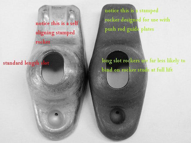
never use both push rod guides and self aligning rockers

youll be far ahead if you carefully read the linked and sub-linked info

some time spent reading related links about your potential valve train issues could prevent lots of potential problems
http://garage.grumpysperformance.co...-pushrods-and-check-info-you-might-need.5931/
http://garage.grumpysperformance.co...rect-custom-length-pushrods.14241/#post-72353
http://garage.grumpysperformance.co...-rockers-and-the-pushrods-rub.198/#post-46839
http://garage.grumpysperformance.com/index.php?threads/press-in-vs-threaded-rocker-studs.2746/
http://garage.grumpysperformance.co...s-tool-swapping-to-1-6-1-ratio-rockers.14761/
http://garage.grumpysperformance.co...rdering-correct-custom-length-pushrods.14241/
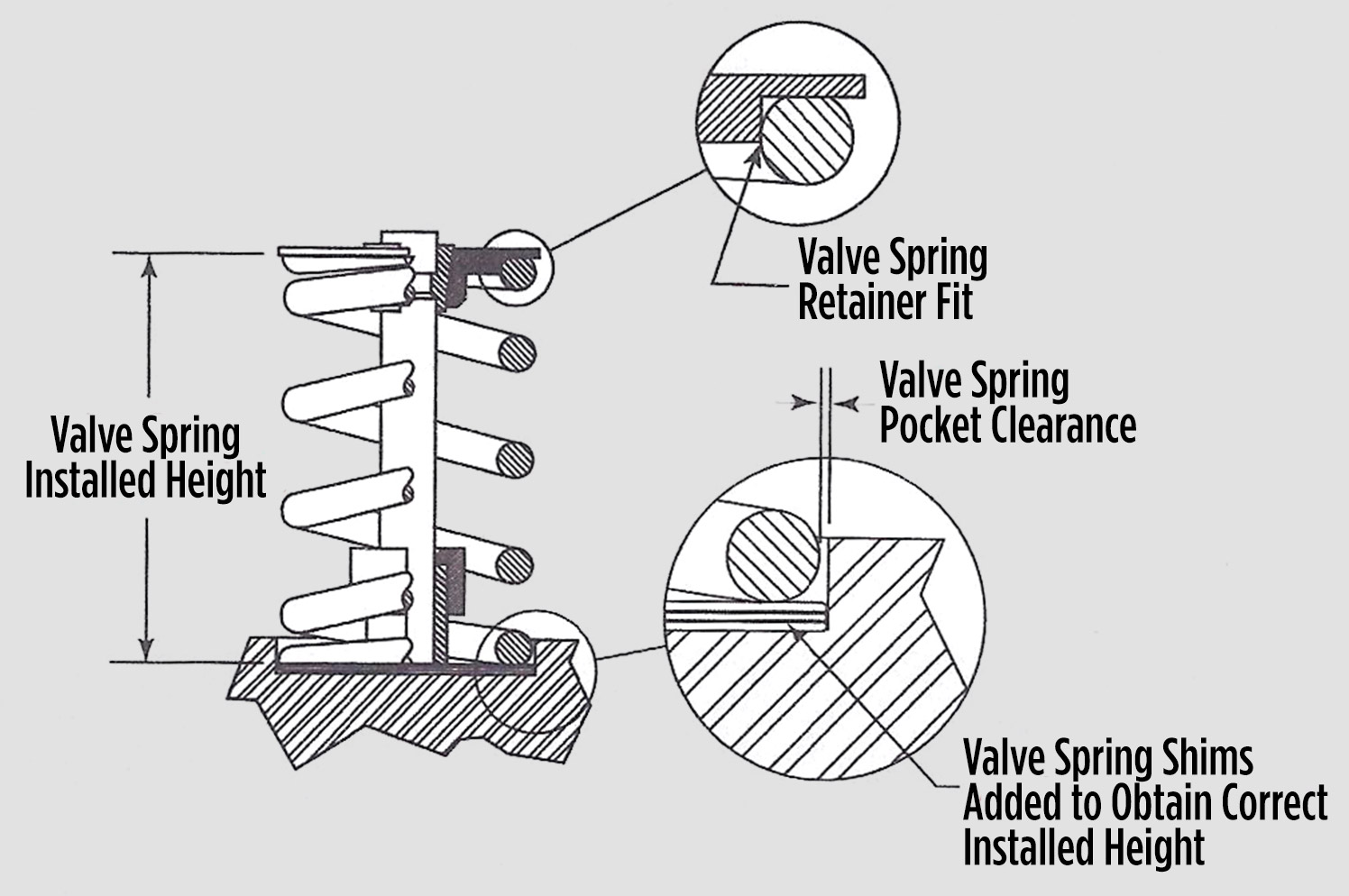
http://garage.grumpysperformance.co...ange-in-valve-spring-iinstalled-height.12791/
http://garage.grumpysperformance.co...1-6-1-ratio-rockers-and-the-pushrods-rub.198/

http://garage.grumpysperformance.com/index.php?threads/wrong-rocker.13987/#post-71250

http://garage.grumpysperformance.co...rect-custom-length-pushrods.14241/#post-72346

http://garage.grumpysperformance.co...train-clearances-and-problems.528/#post-57678

http://garage.grumpysperformance.co...engine-and-bent-two-pushrods.4712/#post-56192

http://garage.grumpysperformance.com/index.php?threads/rocker-push-rod-wear-issues.9815/#post-54088

http://garage.grumpysperformance.co...-in-vs-threaded-rocker-studs.2746/#post-43539

http://garage.grumpysperformance.co...-rockers-and-the-pushrods-rub.198/#post-46839

http://garage.grumpysperformance.co...nd-check-info-you-might-need.5931/#post-18267

http://garage.grumpysperformance.co...all-block-chevy-guide-plates.2839/#post-12739
 
Last edited by a moderator:
push rods must be carefully verified as to being both the correct length and strait, bent pushrods will generally cause either excessive wear or valve train failures,
all push rods should be carefully inspected and cleaned to insure theres no internal debris that will restrict oil flow or cause wear.

http://garage.grumpysperformance.com/index.php?threads/multi-angle-valve-job-related.3143/#post-8387

http://garage.grumpysperformance.co...video-with-info-worth-watching-through.15999/

yes you need to as stated, many times on this and other websites, check all your valve train clearances carefully, but in this case theres almost certainly no cause to be concerned here as the minor difference in spring load rates and installed heights is probably well within the intended valve train and cams design limitations, keep in mind the max cam lift is .520
drawsdf.jpg

those heads (keep in mind that price is for a single (1) cylinder head)
https://www.summitracing.com/parts/tfs-30410001/overview/
rockeroilfeed.jpg

yeah roller cam lifters are considerably taller, thus requiring shorter push rods


use a check tool to verify the correct push rod length
https://www.google.com/search?q=che...&ie=UTF-8#kpvalbx=_ZiKyZKu-I8KjqtsP9vyW-Ak_31

longslotz.jpg

check all valve train geometry and clearance on any engine you assemble or modify the valve train on.
bbcvtq5.jpg

OBVIOUSLY YOULL WANT THE CORRECT VALVE SPRINGS

http://www.competitionproducts.com/1500-1585-OD-Valve-Springs/products/2631/1/0

https://www.summitracing.com/search/part-type/valve-springs

https://www.iskycams.com/cart/valve-springs-c-99.html

http://www.cranecams.com/userfiles/file/334-343.pdf

https://www.racingsprings.com/Valve-Spring/Store/13

http://www.lunatipower.com/Category.aspx?id=23

http://www.pspring.com/products/engine-valve-springs/

http://www.competitionproducts.com/Valve-Springs/departments/49/

http://psisprings.com/products/

http://www.compcams.com/Products/CC-'Valve Springs By Usage'-0.aspx

http://www.racingsprings.com/Beehive-Valve-Springs

https://www.supertechperformance.com/valve-springs-p109

http://www.cvproducts.com/index.php/psi-springs/

you might also want to keep in mind theres a great deal more to setting up a valve train than slapping some springs and retainers and keepers on the valve
s.
read thru the links and sub links as theres a great deal of useful info, that youll want to know.
btw just a bit more info, there are valve spring retainers, valve spring seats, shims, valve retainer keepers etc. that can be used that have different sizes or depths that allow you to change the installed height, or relation of the spring to the valve stem , it compressed height, or the valve springs location in relationship to the stems locking groove
keep in mind shims under the valve springs can be used to raise the spring or shorten the valves installed height, valve locks and retainers can be purchased with non-O.E.M dimensions to adjust the valves installed height or spring load rates
you use either or both depending on the application
a .050 PLUS valve lock moves the retainer .050 higher on the valve stem with no other changes, a plus .050 retainer would move the retainer .050 higher with stock valve locks or an additional .050 if matched to .050 plus locks
if you used a plus .o50 retainer with a set of minus .o50 valve locks the retainer would remain at the stock height on the valve stem

http://www.jegs.com/p/Crane/746983/10002/-1

http://www.jegs.com/p/Moroso/764349/10002/-1

http://www.jegs.com/p/Manley/940089/10002/-1

http://www.jegs.com/p/Comp+Cams/757964/10002/-1
2709946016.jpg

660-42379-16.jpg

valvespringseats.png

valsp1.jpg

valsp2.jpg

valsp3.jpg

valsp4.jpg

prctool.png

youll have to correctly measure the clearance on your heads with the valve springs and cam specs you selected too use to know if you have the correct valve spring installed height and clearances, failure to accurately check frequently results in very expensive repairs and to what new guys frequently blame on the cam when it was a installers ignorance that was the true cause.

https://www.summitracing.com/parts/pro-66902/overview/

https://www.summitracing.com/parts/sum-900032/overview/

https://www.summitracing.com/parts/rsc-pac-t902/overview/

pic16vc.jpg

pic19vc.jpg


springmicv.jpg

vsmt7a.jpg

pic18vc.jpg

pic20vc.jpg


vspr1.jpg

valve springs must be installed at a specific semi compressed and listed installed height,
to provide the listed load rates and clearances,
example

crane110921.jpg

the cam you select will generally come with a suggested listed valve spring load rate and installed height,
(NOTICE THE SUGGESTED INSTALLED HEIGHT WITH THIS CAM IS 1.800"
and the loads are listed)

you must maintain minimum coil bind and retainer to valve seal clearance and proper push-rod and rocker geometry
the distance between the lower edge of the valve spring retainer and the cylinder head is adjustable to achieve the desired valve spring height through the use of valve spring seat cups and shims placed under the valve spring which can be purchased to lock into a stock height, or plus or minus about .050, and valve locks that cam move the retainer (stock or aftermarket) an additional .050 either tighter or longer allowing the valve spring to expand taller, shims can be placed under the valve seat hardened cups that are almost always mandatory on aluminum head but may be optional on iron heads,(O.E.M. cast iron and lower valve spring load rates)

ValveSpringDetail.gif


clear.jpg


valvespringinstalled.gif


springshima.jpg

prctool.png


retain6.jpg


bbcspring2.gif

installedheight.gif


edvalvs.jpg

valvespringseats.png

Installedsp.jpg

valvespringseatsx.png

max lift is installed height minus .060 minus coil bind
drawsdf.jpg


Valvetrain Facts
column_header.png


A pushrod is an eccentrically loaded column due to angularity load and arc motion throughout pushrod travel. Pushrods want to deflect most toward the bottom of the column near the lifter side of the pushrod. This is because of the angularity load. In most cases it is best to use the largest diameter pushrod that will fit in the engine. The increased diameter will lessen deflection and allow better valve train control.


When checking and fitting for pushrod diameter it may be necessary to use a single taper or dual offset taper design, with the large end being toward the bottom. This places the larger diameter and increased mass properly to stiffen the pushrod where it wants to flex the most. The added clearance that the tapered design gives through the head and near the rockerarm can really be helpful. The taper on the tube can also help dampen harmonics in the valvetrain.

With a stiffer pushrod column, increased valvelift should be able to be measured statically in applications using a lot of spring pressure. The higher the engine speed the greater the increase will be at running speed. Keep in mind that by increasing wall thickness to a pushrod column does add strength, the percentage of increase is very small. The large gain in column strength comes from increasing the pushrod diameter.

Do not be overly concerned about pushrod weight. The pushrod is on the slow moving side of the valve train. The additional weight of a heavy wall pushrod usually provides a much needed increase in valve train stability.

facts_schematic_header.png

facts_schematic.png


Note: In this simplified illustration, you can see that pushrod deflection and compression can cause reduced net valve lift, the result of a foreshortened pushrod. Valve timing (duration and timing) can also be affected by inadequate pushrod stiffness.
Note: Adding to the complexity of pushrod loading are compound angles resulting from offset pushrod cups (in lifters) and angularity relationships among the pushrod, valve lifter and rockerarm. Oblique angles contribute to side-loading and complex load patterns placed on the pushrod. Although some degree of pushrod “shock absorbing” is virtually unavoidable, minimizing such deflection and compression is critical for maintaining proper valve timing.

threepiece_header.png


Before we explain why we manufacture only modular pushrods, we must first stop and describe the function of a pushrod. In simple terms, pushrods transfers energy from the lifter to the rockerarm. If a pushrod is not correctly matched to the application, incorrect valve lift and valve timing can cause engine failure. With a properly matched pushrod you will achieve maximum horsepower and ultimate valve train wear.
To achieve the proper pushrod for an engine, you must decide the pushrod length, diameter, wall thickness, materials, heat treating and end configurations to match the specific engine components and application. This may seem like a fairly easy process but to accomplish this there are several things that must be considered. This is why we only manufacture custom modular pushrods.


    • 1. Each end in a pushrod must be compatible with its mating components. This requires the use of material that can function as a bearing and at the same time be as impact resistant as possible. As an additional benefit, this also allows for an unlimited amount of tip designs.
    • 2. With a modular pushrod it allows the flexibility to choose “unique” tapers for clearance issues. Also changing the wall thickness, diameter and tapering the tube will change the natural frequency.
    • 3. The column of the pushrod must be made out of a different material and heat treated differently than the tips. It must provide the strength to withstand the combined abuse of high engine speeds and cylinder pressure. By using a dissimilar material from the pushrod end we are able to utilize any heat treat we desire. In most applications we use a material that is commonly available 4130/4135 tubing. In our series 2 & 4 we use a MeloniteTM process for durability and wear resistance for guide plate use. In our series 5 we use a proprietary heat treating process to increase the material value to a Rockwell of approximately 46 “C”. This is critical to the function of a pushrod column and 4130/4135 is very tough, forgiving and durable when used at approximately 46 Rockwell “C”. We also offer a proprietary heat treated solid bar S-7 tool steel pushrod which is the same material used to produce quality chisels and hammers. It is very impact resistant and is the perfect material for extreme applications.
In our estimation the only reason to ever produce a one piece pushrod would be because of the reduced cost to manufacture. We are here to produce the highest quality pushrods available and for the reasons listed here we DO NOT manufacture one piece pushrods.


three_piecepushrod.jpg


Proper Pushrod Diameter
When checking for pushrod diameter you need to first establish the length needed. Then you must turn the engine over manually to check for tight clearance areas by the Cylinder Head, Lifer Bar and other close tolerance areas. We prefer .010 thousands at the Cylinder Head and .020 at the Lifter and Lifter Bar.

We prefer you to fit the largest pushrod you can in the area you have to work with. Sometimes small modifications need to be made.

Manton offers different size sleeves that fit over a pushrod tool to help assure proper clearance. The sleeve is used by sliding up and down the length checking tool with 0-rings holding the sleeve in proper position to assure clearance in these areas as needed.

length checking tool with 0-rings holding the sleeve in proper position to assure clearance in these areas as needed.

Rockerarm Geometry and Proper Pushrod Length


Many variables directly affect determing proper pushrod length. Pushrod length is affected by all of the variables listed below.
• Block deck height
• Head deck height
• Cam base circle diameter
• Head stud boss height / rockerarm stand mounting pad
• Rockerarm design
• Lifter receiver cup height
• Valve stem height

Remember that every engine is different because the combination of these variables change from one engine to another. Take the time necessary to determine proper pushrod length with each engine you build. Do not assume that your pushrod length is the same as your friends engine. We have given some guidelines in this section to help you determine proper pushrod length for both roller rockerarms and shoe rockerarms. Each type of rockerarm style has different instructions.With shaft mounted rockerarms, raising or lowering the stands to change the rockerarm shaft height is usually necessary to obtain proper rockerarm geometry. With stud mounted rockerarms, changing the pushrod length achieves the same effect.


    • 1. Obtain an adjustable checking pushrod (available from Manton)
    • 2. Light duty checking springs must be used in place of valve springs to allow you to rotate the valve train and check for proper contact pattern on the valve stem.
    • 3. You will need an accurate measuring device to measure your adjustable pushrod once you have locked your adjustable pushrod at the correct length.
    • 4. Ball/Ball designs are to be ordered by overall length measurement. (The standard flat diameter on the ends of the pushrods is .100).
    • 5. Ball/Cup designs are most properly ordered by the effective length. This length is measured from the bottom of the cup radius to the tip of the ball. Overall length can also be given but tell us how deep the cup depth is. Make sure when ordering ball/cup pushrods that you specify effective or overall length.
measurement.jpg


Proper Pushrod Length With a Shoe Rockerarm
See “Diagram A” for Shoe Rockerarm
When using your adjustable pushrod checking tool and checking springs you want the contact spot to start on the intake side of the valve tip with the lifter on the base of the camshaft (position #1). At approximately 1/3 lift the contact spot should be in the center of the valve tip (position #2). At full lift the contact spot should be the same distance past the center of the valve tip toward the exhaust side as it was when the lifter was on the base of the camshaft (position #3). Fully closed is back to position #1.

Proper Pushrod Length With Roller Rockerarms
See “Diagram B” for Roller Rockerarm
As in diagram A you should use a checking spring during this procedure. This allows you to rotate the valve train without damaging the checking pushrod and eliminates the unwanted deflection that would occur from spring pressure.

To obtain the roller positions listed below you will be re-locating the rocker arm pivot point (rocker shaft). By moving the shaft up or down the roller contact position on the valve will change.

With the valve completely closed and the lifter on the base circle of the camshaft, the roller should contact the valve at position #1 as shown in the diagram. As the valve train is rotated to 1/2 lift the roller will have traveled as far as it can and will stop at position #2. Continue to rotate the engine and at full lift the roller contact will be at its starting point. We will call this position #3. If the roller is not in exactly the same position at full lift as it was when the valve was completely closed, the rocker shaft must be moved. If the roller stops early the shaft must be shimmed up. If the roller stops late the shaft must be moved down. As you continue to rotate the valve train the roller will move back to position #4 when the valve is at half lift on the closing side and will finish at position #5 when the valve is completely closed.

length_graphic.jpg

diameter_header.png


products_graphic.png


We offer many wall thicknesses which allows you to vary the frequency and column strength of the pushrod.
This provides a unique tunable valve train tool.


related info you really need to read
http://garage.grumpysperformance.co...ring-installation-questions.12833/#post-66460

http://garage.grumpysperformance.co...-loads-and-installed-height.10709/#post-46658

http://garage.grumpysperformance.co...ve-spring-iinstalled-height.12791/#post-66038

http://garage.grumpysperformance.co...train-clearances-and-problems.528/#post-57678

http://garage.grumpysperformance.com/index.php?threads/valve-springs.9613/#post-50556

http://garage.grumpysperformance.com/index.php?threads/valve-train-clearances-and-problems.528/

push rod to short
WIDE SWEEP ON VALVE TIP FROM ROCKER ADDS ADDITIONAL,
SIDE LOAD WEAR
long.jpg

push rod to long
correct.jpg

yes you need to as stated, many times on this and other websites, check all your valve train clearances carefully,
drawsdf.jpg


those heads (keep in mind that price is for a single (1) cylinder head)
https://www.summitracing.com/parts/tfs-30410001/overview/

OBVIOUSLY YOULL WANT THE CORRECT VALVE SPRINGS

http://www.competitionproducts.com/1500-1585-OD-Valve-Springs/products/2631/1/0

https://www.summitracing.com/search/part-type/valve-springs

https://www.iskycams.com/cart/valve-springs-c-99.html

http://www.cranecams.com/userfiles/file/334-343.pdf

https://www.racingsprings.com/Valve-Spring/Store/13

http://www.lunatipower.com/Category.aspx?id=23

http://www.pspring.com/products/engine-valve-springs/

http://www.competitionproducts.com/Valve-Springs/departments/49/

http://psisprings.com/products/

http://www.compcams.com/Products/CC-'Valve Springs By Usage'-0.aspx

http://www.racingsprings.com/Beehive-Valve-Springs

https://www.supertechperformance.com/valve-springs-p109

http://www.cvproducts.com/index.php/psi-springs/

any time you find the valve train producing a noise its generally a clearance issue or a worn part,
to help locate the source of the noise, take off the valve cover and, have a buddy start the engine,
press down on the rockers individually at idle with the palm of your hand,
,if the lifter, rocker or other valvetrain component is worn or mal-adjusted,
the sound on each valve assembly will change as pressures applied to the rocker with the heal of your hand on the rocker testing individually at idle,
obviously done before oil temps rise too far and
visually check for cracked valve springs,
bent or loose rocker studs and
rocker slots that contact the rocker stud

and
missing valve lock keys in the valve spring retainer
Id also suggest you swap rockers if you find one causing the noise,
burn or worn rocker balls in the rocker can cause this,
and that helps you isolate the defective component

https://www.chevydiy.com/small-block-chevy-rocker-arms-studs-pushrods-lifters-guide/

6-4.jpg


Stamped rockers use a slot cut in the base of the rocker that allows the rocker to move relative to the stud. With higher lift cams, make sure there is a minimum of 0.050 inches clearance between the end of the rocker slot and the rocker stud at max lift.


2-4.jpg


13-3.jpg


In the mid 1980s, all production small blocks began using “guided” rocker arms that use two small guides that straddle the valve tip to locate the rocker arm tip. Guided or “rail” rockers should not be used with guideplates since this could create a binding situation that would break parts.
its not unusual to find mixed sets on older engines:mad:


let us know what you find:rolleyes::p

you might also want to keep in mind theres a great deal more to setting up a valve train than slapping some springs and retainers and keepers on the valve
s.
read thru the links and sub links as theres a great deal of useful info, that youll want to know.
btw just a bit more info, there are valve spring retainers, valve spring seats, shims, valve retainer keepers etc. that can be used that have different sizes or depths that allow you to change the installed height, or relation of the spring to the valve stem , it compressed height, or the valve springs location in relationship to the stems locking groove
keep in mind shims under the valve springs can be used to raise the spring or shorten the valves installed height, valve locks and retainers can be purchased with non-O.E.M dimensions to adjust the valves installed height or spring load rates
you use either or both depending on the application
a .050 PLUS valve lock moves the retainer .050 higher on the valve stem with no other changes, a plus .050 retainer would move the retainer .050 higher with stock valve locks or an additional .050 if matched to .050 plus locks
if you used a plus .o50 retainer with a set of minus .o50 valve locks the retainer would remain at the stock height on the valve stem
cca-4929.jpg


0607em_17_z+engine_assembly+shims.jpg

viewtopic.php?f=52&t=181
http://www.jegs.com/p/Crane/746983/10002/-1

http://www.jegs.com/p/Moroso/764349/10002/-1

http://www.jegs.com/p/Manley/940089/10002/-1

http://www.jegs.com/p/Comp+Cams/757964/10002/-1
2709946016.jpg

660-42379-16.jpg

valvespringseats.png

valsp1.jpg

valsp2.jpg

valsp3.jpg

valsp4.jpg

prctool.png

youll have to correctly measure the clearance on your heads with the valve springs and cam specs you selected too use to know if you have the correct valve spring installed height and clearances, failure to accurately check frequently results in very expensive repairs and to what new guys frequently blame on the cam when it was a installers ignorance that was the true cause.

https://www.summitracing.com/parts/pro-66902/overview/

https://www.summitracing.com/parts/sum-900032/overview/

https://www.summitracing.com/parts/rsc-pac-t902/overview/

pic16vc.jpg

pic19vc.jpg


springmicv.jpg

vsmt7a.jpg

pic18vc.jpg

pic20vc.jpg


vspr1.jpg

valve springs must be installed at a specific semi compressed and listed installed height,
to provide the listed load rates and clearances,
example

crane110921.jpg

the cam you select will generally come with a suggested listed valve spring load rate and installed height,
(NOTICE THE SUGGESTED INSTALLED HEIGHT WITH THIS CAM IS 1.800"
and the loads are listed)

you must maintain minimum coil bind and retainer to valve seal clearance and proper push-rod and rocker geometry
the distance between the lower edge of the valve spring retainer and the cylinder head is adjustable to achieve the desired valve spring height through the use of valve spring seat cups and shims placed under the valve spring which can be purchased to lock into a stock height, or plus or minus about .050, and valve locks that cam move the retainer (stock or aftermarket) an additional .050 either tighter or longer allowing the valve spring to expand taller, shims can be placed under the valve seat hardened cups that are almost always mandatory on aluminum head but may be optional on iron heads,(O.E.M. cast iron and lower valve spring load rates)

ValveSpringDetail.gif


clear.jpg


valvespringinstalled.gif


springshima.jpg

prctool.png


retain6.jpg


bbcspring2.gif

installedheight.gif


edvalvs.jpg

valvespringseats.png

Installedsp.jpg

valvespringseatsx.png

max lift is installed height minus .060 minus coil bind
drawsdf.jpg

related info you really need to read
http://garage.grumpysperformance.co...ring-installation-questions.12833/#post-66460

http://garage.grumpysperformance.co...-loads-and-installed-height.10709/#post-46658

http://garage.grumpysperformance.co...ve-spring-iinstalled-height.12791/#post-66038

http://garage.grumpysperformance.co...train-clearances-and-problems.528/#post-57678

http://garage.grumpysperformance.com/index.php?threads/valve-springs.9613/#post-50556

http://garage.grumpysperformance.com/index.php?threads/valve-train-clearances-and-problems.528/

push rod to short
WIDE SWEEP ON VALVE TIP FROM ROCKER ADDS ADDITIONAL,
SIDE LOAD WEAR
long.jpg

push rod to long
correct.jpg


push rod length correct
AS CLOSE TO CENTER AS POSIABLE BUT BEING CENTERED IS LESS IMPORTANT THAN MINIMAL SWEEP ON THE VALVE TIP< INDICATING MINIMAL SIDE LOADING

http://garage.grumpysperformance.co...-pushrods-and-check-info-you-might-need.5931/
http://www.summitracing.com/search/...d-length-checkers?autoview=SKU&ibanner=SREPD5
Proform Pushrod Length Checkers 66789 SBC 3/8" rocker studs

Proform Pushrod Length Checkers 66790 SBC 7/16" rocker studs

Proform Pushrod Length Checkers 66806 BBC 7/16" rocker studs
a few simple tools will tell you if clearances are ok

12cal.jpg


Feeler-Gauge.jpg


READ THESE LINKS CAREFULLY

http://garage.grumpysperformance.co...e-springs-and-setting-up-the-valve-train.181/

http://garage.grumpysperformance.com/index.php?threads/rocker-push-rod-wear-issues.9815/

http://garage.grumpysperformance.com/index.php?threads/checking-piston-to-valve-clearances.399/

http://garage.grumpysperformance.com/index.php?threads/valve-train-clearances-and-problems.528/
http://www.northerntool.com/shop/tools/product_200308979_200308979
your going to need a cheap but reasonably accurate caliper to accurately measure push rods

http://garage.grumpysperformance.com/index.php?threads/valve-train-clearances-and-problems.528/


http://www.superchevy.com/how-to/vemp-0703-corvette-rocker-arms/

push rod to short
WIDE SWEEP ON VALVE TIP FROM ROCKER ADDS ADDITIONAL,
SIDE LOAD WEAR
long.jpg

push rod to long
correct.jpg


push rod length correct
AS CLOSE TO CENTER AS POSIABLE BUT BEING CENTERED IS LESS IMPORTANT THAN MINIMAL SWEEP ON THE VALVE TIP< INDICATING MINIMAL SIDE LOADING

Proform Cam Checker Tools
degreetool.jpg


TFS-9001.jpg


clearancefail.jpg

heres a bit of useful related push rod length info
Big Block Chevy, Standard Length Big Block Intake 3/8" / .080" 8.275"
295-7941-8 Big Block Chevy, Standard Length Big Block Exhaust 3/8" / .080" 9.250"
295-7969-8 Big Block Chevy, Standard Big Block +.100" Long Intake 3/8" / .080" 8.375"
295-7979-8 Big Block Chevy, Standard Big Block +.100" Long Exhaust 3/8" / .080" 9.350"
295-7951-8 Big Block Chevy, Standard Length Big Block Tall Deck Intake 3/8" / .080" 8.675"
295-7961-8 Big Block Chevy, Standard Length Big Block Tall Deck Exhaust 3/8" / .080" 9.650"
295-7800 V8 396-454 Retro Fit Pushrod Set, Intake & Exhaust, 1965-Present
3/8" / .080"
3/8" / .080" 7.725 Int.
8.675 Exh
295-7913-16 Small Block Chevy, Standard Length Small Block Chevy 3/8" / .080" 7.800"
295-7984-16 Small Block Chevy, +.100" Long 3/8" / .080" 7.900"
295-7934-16 Big Block Ford, Standard Length Ford `72-'78 429-460 3/8" / .080" 8.550"
295-7951-16 Big Block Ford, Standard Length Ford `69-'71 429-460 3/8" / .080" 8.675"
295-7582-16 Oldsmobile, Std Length 455 5/16" 9.550"

12cal.jpg


http://www.summitracing.com/parts/pro-66979
66979a.jpg

66979b.jpg

66979c.png

prctool.png

http://www.summitracing.com/search/...d-length-checkers?autoview=SKU&ibanner=SREPD5
Proform Pushrod Length Checkers 66789 SBC 3/8" rocker studs

Proform Pushrod Length Checkers 66790 SBC 7/16" rocker studs

Proform Pushrod Length Checkers 66806 BBC 7/16" rocker studs

verify your correct geometry first
coat both ends of the push rods with moly assembly lube when installing them.
crn-99004-1_w.jpg


http://www.thedirtforum.com/pushrodlengths.htm

http://garage.grumpysperformance.com/index.php?threads/finding-matched-valve-spring-required.13774/

http://www.compcams.com/catalog/278.html

http://www.carcraft.com/techarticles/11 ... index.html


http://mantonpushrods.com/

http://www.hotrod.com/how-to/engine/ctrp-0611-rocker-arm-valvetrain-geometry/

http://garage.grumpysperformance.com/index.php?threads/valve-train-clearances-and-problems.528/

http://www.summitracing.com/search/product-line/trick-flow-chromoly-pushrods

http://www.summitracing.com/search/brand/manley/product-line/manley-pushrods?SortBy=BestKeywordMatch&SortOrder=Ascending

http://www.hotrod.com/how-to/engine/116-0401-setting-pushrod-length/

http://www.compcams.com/catalog/COMP2012/pdf/COMP_Catalog_2012_292-311.pdf

http://garage.grumpysperformance.co...e-used-prw-stainless-steel-rocker-arms.14896/


Ive used both, styles in the past with good results but if you feel the snap ring retention design is superior than by all means get those,, and yes from a mechanical strength stand point theres no contest the snap ring design retention is at least in theory stronger as it has far more surface area resisting the clip coming loose,
but I would point out that the quality of the machine work , the type of lubricants used,
the metal alloy in both cam and lifters, the components heat treatment
valve train clearances, valve train geometry
oil system modifications
and several other factors are much more likely to be the cause or prevention of a cam/lifter failure.


READING THE LINKS AND SUB LINKS WILL HELP

http://garage.grumpysperformance.co...lifter-to-increase-oil-flow.11152/#post-49968

http://garage.grumpysperformance.co...ear-articles-you-need-to-read.282/#post-52473

snapclip.jpg

snapring.png


http://garage.grumpysperformance.com/index.php?threads/oil-system-mods-that-help.2187/

http://garage.grumpysperformance.co...e-train-clearances-and-problems.528/#post-668

http://garage.grumpysperformance.com/index.php?threads/basic-info-on-your-v8-lube-system.52/


related info youll need

http://garage.grumpysperformance.co...g-block-pushrod-guide-plates.4596/#post-18401


http://garage.grumpysperformance.co...-rockers-and-the-pushrods-rub.198/#post-49226

http://garage.grumpysperformance.co...s-on-valve-spring-pressures.10268/#post-43516

http://garage.grumpysperformance.co...e-springs-and-setting-up-the-valve-train.181/

http://garage.grumpysperformance.co...ind-height-060-safety-margin.4957/#post-13739

http://garage.grumpysperformance.co...ich-is-best-steel-or-aluminum.3124/#post-8330

http://garage.grumpysperformance.co...mall-block-chevy-guide-plates.2839/#post-7344
 
Last edited:
steelcomp said:
This is just a little insight into what I do here almost on a daily basis and what we run into.
Setting up rocker geometry for a customer. Customer sent in their heads and another brand of rockers. We did the cam and provided new Morel lifters. This is a solid roller deal with about .740 net intake, .705 net ex lift. Heads are Dart 355 CNC heads.
I did my normal procedure and this was the first thing I noticed. This was on the intake:
IMAG4348.jpg


This is where the roller tip sat on the valve @ zero lift with proper pushrod length for that rocker. To note; it will only move further to the outside as the valve starts to open. This is as good as it gets for these rockers;
IMAG4352.jpg


Here's the Crane rocker, zero lift, proper pushrod length...;
IMAG4359.jpg


...and here's where it sits. Something else to note; the pushrod length for the Crane rocker was .110" shorter to get the same geometry as the other rocker;

IMAG4355.jpg


This is on the exhaust side.
Customer's rocker with proper pushrod length, zero lift.

IMAG4344.jpg


This is with the Crane rocker, proper pushrod length, zero lift. In this case the Crane pushrods were .180" shorter for the same geometry.

crane345.jpg

stamprockf.jpg

http://www.summitracing.com/parts/lun-85025
stampedcvrockersa.jpg

the grooved rocker pivot ball design was an effort by G.M. engineering to economically solve the issue of marginal oil flow causing rocker ball galling, and resulting noisy, or broken valve trains


rockeroilfeed.jpg


rockstcl.jpg


check all valve train geometry and clearance on any engine you assemble or modify the valve train on.
bbcvtq5.jpg


bbcrk1.jpg


rockeroilfeed.jpg

longslot.jpg

The center to center distance of the fulcrum length was .045" longer on the customer's rockers than on the Crane rockers. Pretty obvious when you see where they sit in relation to each other on the valve tip.

There isn't much difference between a BB Ford rocker and a BB Chev rocker and some rocker manufacturers have come up with a "one rocker fits all" dimension for their BBF and BBC rockers. Something sort of half way between. Crane has a dedicated extrusion for every rocker they build. When you're just centering the roller on the tip of the valve, this isn't an obvious problem but as you can see here, when you try to establish proper geometry the problem becomes quite obvious.

Hope this gives a little useful insight into why we always recommend Crane Gold rockers for our stud mount apps.
 
Last edited:
fact
valve train components RARELY just break for no reason

Fact
it takes hundreds of pounds of force to bend push-rods

Fact
IMPROPER CLEARANCES can destroy a valve train or cam in under 30 seconds

Fact
the most common REASON is INCORRECT CLEARANCE OR ROCKER GEOMETRY, or failure to adjust valves properly

FACT
reading links and sub-links helps you isolate the cause, of a failure,... carefully reading through will allow you to avoid having the problem

Fact
In most cases its operator error , or failure to correctly set-up and clearance the valve train that causes problems

Fact
20 minutes -to a couple hours well spent asking questions, and being damn sure you understand the answers, can save you weeks of repairs and machine shop bills

Fact
NO ONE does this the first few times without making SOME mistakes


Fact
having an experienced mentor help guide you through the process tends to reduce the chances of failure

Fact
joining several local corvette or muscle car clubs and helping the older more experienced members work on their cars, and letting them help you on yours, speeds the learning curve
The answer, too when or if you need longer valves, depends on the engine valve train geometry and the cylinder head design,
it differs from intake to exhaust on most engines also.
I've usually found longer valves are required if the valve lift exceeds about .630, but theres no rock solid rule, you need to do some research and call your machine shop and the cylinder head manufacture. the load rate also plays a significant part in that decision, thinner valve spring seats require thicker castings for structural rigidity.
valve lift alone withing reasonable limits, has little to do with the need for longer valves, but as the lift increases the difference between the spring installed height and its spring bind or coil stack obviously changes.
if your standard valve spring has lets say a 1.70 installed height and a 1.20 coil bind or stack height you would generally be looking at .500 difference, subtract the .060 minimum clearance,
added to prevent binding issues for coil bind, that only leaves you .440 useful valve clearance.
now you can machine the heads in the valve spring seat area only minimally as the valve spring seats are over the coolant passages and generally ,
the manufacturers will tell you you can only machine the valve seat so far from the O.E.M. original location,
and in many cylinder heads you can't machine deeper without reducing the heads functional strength or causing problems.
if you can,t increase the installed height, of the valve spring by machining extra clearance downward, into the spring seat, the other answer is found in longer valve stem length and longer push rods too keep the rocker geometry correct.
vspr1.jpg


Installedsp.jpg


drawsdf.jpg


portsd2.jpg

before as cast
portse1.jpg


Valvetrain Facts
column_header.png


A pushrod is an eccentrically loaded column due to angularity load and arc motion throughout pushrod travel. Pushrods want to deflect most toward the bottom of the column near the lifter side of the pushrod. This is because of the angularity load. In most cases it is best to use the largest diameter pushrod that will fit in the engine. The increased diameter will lessen deflection and allow better valve train control.


When checking and fitting for pushrod diameter it may be necessary to use a single taper or dual offset taper design, with the large end being toward the bottom. This places the larger diameter and increased mass properly to stiffen the pushrod where it wants to flex the most. The added clearance that the tapered design gives through the head and near the rockerarm can really be helpful. The taper on the tube can also help dampen harmonics in the valvetrain.

With a stiffer pushrod column, increased valvelift should be able to be measured statically in applications using a lot of spring pressure. The higher the engine speed the greater the increase will be at running speed. Keep in mind that by increasing wall thickness to a pushrod column does add strength, the percentage of increase is very small. The large gain in column strength comes from increasing the pushrod diameter.

Do not be overly concerned about pushrod weight. The pushrod is on the slow moving side of the valve train. The additional weight of a heavy wall pushrod usually provides a much needed increase in valve train stability.

facts_schematic_header.png

facts_schematic.png


Note: In this simplified illustration, you can see that pushrod deflection and compression can cause reduced net valve lift, the result of a foreshortened pushrod. Valve timing (duration and timing) can also be affected by inadequate pushrod stiffness.
Note: Adding to the complexity of pushrod loading are compound angles resulting from offset pushrod cups (in lifters) and angularity relationships among the pushrod, valve lifter and rockerarm. Oblique angles contribute to side-loading and complex load patterns placed on the pushrod. Although some degree of pushrod “shock absorbing” is virtually unavoidable, minimizing such deflection and compression is critical for maintaining proper valve timing.

threepiece_header.png


Before we explain why we manufacture only modular pushrods, we must first stop and describe the function of a pushrod. In simple terms, pushrods transfers energy from the lifter to the rockerarm. If a pushrod is not correctly matched to the application, incorrect valve lift and valve timing can cause engine failure. With a properly matched pushrod you will achieve maximum horsepower and ultimate valve train wear.
To achieve the proper pushrod for an engine, you must decide the pushrod length, diameter, wall thickness, materials, heat treating and end configurations to match the specific engine components and application. This may seem like a fairly easy process but to accomplish this there are several things that must be considered. This is why we only manufacture custom modular pushrods.


  • 1. Each end in a pushrod must be compatible with its mating components. This requires the use of material that can function as a bearing and at the same time be as impact resistant as possible. As an additional benefit, this also allows for an unlimited amount of tip designs.
  • 2. With a modular pushrod it allows the flexibility to choose “unique” tapers for clearance issues. Also changing the wall thickness, diameter and tapering the tube will change the natural frequency.
  • 3. The column of the pushrod must be made out of a different material and heat treated differently than the tips. It must provide the strength to withstand the combined abuse of high engine speeds and cylinder pressure. By using a dissimilar material from the pushrod end we are able to utilize any heat treat we desire. In most applications we use a material that is commonly available 4130/4135 tubing. In our series 2 & 4 we use a MeloniteTM process for durability and wear resistance for guide plate use. In our series 5 we use a proprietary heat treating process to increase the material value to a Rockwell of approximately 46 “C”. This is critical to the function of a pushrod column and 4130/4135 is very tough, forgiving and durable when used at approximately 46 Rockwell “C”. We also offer a proprietary heat treated solid bar S-7 tool steel pushrod which is the same material used to produce quality chisels and hammers. It is very impact resistant and is the perfect material for extreme applications.
In our estimation the only reason to ever produce a one piece pushrod would be because of the reduced cost to manufacture. We are here to produce the highest quality pushrods available and for the reasons listed here we DO NOT manufacture one piece pushrods.


three_piecepushrod.jpg


Proper Pushrod Diameter
When checking for pushrod diameter you need to first establish the length needed. Then you must turn the engine over manually to check for tight clearance areas by the Cylinder Head, Lifer Bar and other close tolerance areas. We prefer .010 thousands at the Cylinder Head and .020 at the Lifter and Lifter Bar.

We prefer you to fit the largest pushrod you can in the area you have to work with. Sometimes small modifications need to be made.

Manton offers different size sleeves that fit over a pushrod tool to help assure proper clearance. The sleeve is used by sliding up and down the length checking tool with 0-rings holding the sleeve in proper position to assure clearance in these areas as needed.

length checking tool with 0-rings holding the sleeve in proper position to assure clearance in these areas as needed.

Rockerarm Geometry and Proper Pushrod Length


Many variables directly affect determing proper pushrod length. Pushrod length is affected by all of the variables listed below.
• Block deck height
• Head deck height
• Cam base circle diameter
• Head stud boss height / rockerarm stand mounting pad
• Rockerarm design
• Lifter receiver cup height
• Valve stem height

Remember that every engine is different because the combination of these variables change from one engine to another. Take the time necessary to determine proper pushrod length with each engine you build. Do not assume that your pushrod length is the same as your friends engine. We have given some guidelines in this section to help you determine proper pushrod length for both roller rockerarms and shoe rockerarms. Each type of rockerarm style has different instructions.With shaft mounted rockerarms, raising or lowering the stands to change the rockerarm shaft height is usually necessary to obtain proper rockerarm geometry. With stud mounted rockerarms, changing the pushrod length achieves the same effect.


  • 1. Obtain an adjustable checking pushrod (available from Manton)
  • 2. Light duty checking springs must be used in place of valve springs to allow you to rotate the valve train and check for proper contact pattern on the valve stem.
  • 3. You will need an accurate measuring device to measure your adjustable pushrod once you have locked your adjustable pushrod at the correct length.
  • 4. Ball/Ball designs are to be ordered by overall length measurement. (The standard flat diameter on the ends of the pushrods is .100).
  • 5. Ball/Cup designs are most properly ordered by the effective length. This length is measured from the bottom of the cup radius to the tip of the ball. Overall length can also be given but tell us how deep the cup depth is. Make sure when ordering ball/cup pushrods that you specify effective or overall length.
measurement.jpg


Proper Pushrod Length With a Shoe Rockerarm
See “Diagram A” for Shoe Rockerarm
When using your adjustable pushrod checking tool and checking springs you want the contact spot to start on the intake side of the valve tip with the lifter on the base of the camshaft (position #1). At approximately 1/3 lift the contact spot should be in the center of the valve tip (position #2). At full lift the contact spot should be the same distance past the center of the valve tip toward the exhaust side as it was when the lifter was on the base of the camshaft (position #3). Fully closed is back to position #1.

Proper Pushrod Length With Roller Rockerarms
See “Diagram B” for Roller Rockerarm
As in diagram A you should use a checking spring during this procedure. This allows you to rotate the valve train without damaging the checking pushrod and eliminates the unwanted deflection that would occur from spring pressure.

To obtain the roller positions listed below you will be re-locating the rocker arm pivot point (rocker shaft). By moving the shaft up or down the roller contact position on the valve will change.

With the valve completely closed and the lifter on the base circle of the camshaft, the roller should contact the valve at position #1 as shown in the diagram. As the valve train is rotated to 1/2 lift the roller will have traveled as far as it can and will stop at position #2. Continue to rotate the engine and at full lift the roller contact will be at its starting point. We will call this position #3. If the roller is not in exactly the same position at full lift as it was when the valve was completely closed, the rocker shaft must be moved. If the roller stops early the shaft must be shimmed up. If the roller stops late the shaft must be moved down. As you continue to rotate the valve train the roller will move back to position #4 when the valve is at half lift on the closing side and will finish at position #5 when the valve is completely closed.

length_graphic.jpg

diameter_header.png


products_graphic.png


We offer many wall thicknesses which allows you to vary the frequency and column strength of the pushrod.
This provides a unique tunable valve train tool.


marvel.jpg

plewsoilm.jpg

http://www.plews-edelmann.com/oil-cans-and-oilers/
pre-oiling the rockers before starting an engine the first time helps prevent problems
http://garage.grumpysperformance.co...e-springs-and-setting-up-the-valve-train.181/
prod_1588185312.jpg

https://www.craftsman.com/products/craftsman-mach-series-14-piece-3-8-t-handle-driver-and-bit-set
http://garage.grumpysperformance.com/index.php?threads/adjusting-valves.196/

http://garage.grumpysperformance.co...ear-articles-you-need-to-read.282/#post-52017

http://www.cylinderheadsupply.com/valve-guide-tools-guide-top-cutters.html

http://garage.grumpysperformance.co...1-6-1-ratio-rockers-and-the-pushrods-rub.198/

http://garage.grumpysperformance.co...lve-springs-loads-and-installed-height.10709/

http://garage.grumpysperformance.co...caused-hydraulic-lifters-to-come-apart.10482/

http://garage.grumpysperformance.co...1-6-1-ratio-rockers-and-the-pushrods-rub.198/
 
Last edited:
do the roller tip rockers with the ball pivot fulcrums gain you any real advantage?

the roller tip and ball socket fulcrum design rockers don,t reduce friction much as easily 90% plus of the frictions generated in the fulcrum area not the valve tips
cca-1411.jpg


aluminum rockers save weight, reduce friction and reduce heat transfer to the oil but are subject to fatigue so should be changed after about 40K -60K of street use.
(THAT ASSUMES O.E.M. valve spring load rates , rarely exceeding 6000 rpm)
heres an aluminum rocker used on only a 370 lb load max rate valve spring ,
after awhile that failed due too fatigue stress
compaluminumfatigue.jpg


http://www.hotrod.com/how-to/engine/ctrp-0703-rocker-arm-comparison/

http://www.hotrod.com/how-to/engine/116-0101-roller-rocker-ratio-test/

http://garage.grumpysperformance.co...ch-is-best-steel-or-aluminum.3124/#post-51904

http://www.superchevy.com/how-to/engines-drivetrain/sucp-0202-rocker-arm-ratio/

http://www.mustangandfords.com/how-to/engine/mmfp-1101-roller-rocker-arms/

http://www.crower.com/media/pdf/2008b/153-155.pdf

http://www.lunatipower.com/Tech/Valvetrain/HowToVerifyValvetrainGeometry.aspx
keep in mind all roller rockers do not have identical dimensions, crower offers .050 off set trunion designs ans the designs dimensions do differ slightly between manufacturers
80-spring_4_549e6142e0344259e9381cdab70222fdb181d8ec.jpg


crn-10751-16_w.jpg

THE BETTER steel rockers are considerably stronger than most aluminum rockers and that extra strength allows for larger bearings that can distribute the load even more efficiently, obviously theres cheap versions of rockers and quality so shop carefully.
your roller tip and ball socket rockers are generally worth 5-8 hp max, the true roller rockers easily twice that from reduced friction and more precise valve lift.
plus the added benefit of lower oil temps being generated.

rocker-armm.jpg


The problem with aluminum isn't so much heat, it's just pure mechanical fatigue.

http://en.wikipedia.org/wiki/Fatigue_(material)

Stress on, stress off, repeat. Eventually the metal breaks. Most steels don't really fail by that particular mechanism, but for aluminum, and to a lesser extent titanium, it's their primary failure mode. The crappy thing about that is, the stress doesn't have to be ANYWHERE NEAR the material's tensile strength; even relatively mild stresses will catch up with it eventually, if they're apllied cyclically like that. Which of course, is exactly how a rocker spends its life. Thus making aluminum about the poorest possible materials choice.


stating the "ROLLER TIP IN A ROCKER CONTRIBUTES VERY LITTLE TO REDUCING FRICTION, well,
its hardly news that a properly adjusted rocker and the "ROLLER TIP) barely moved across the valve tip, a total sweep distance of .080-.060 is rather common, hardly ROLLING laterally, the distance is generally less than a 1/3rd of the valve stem diam.


VALVE SHUT
rockertoretainer.jpg


MAX LIFT
rockertoretainer1.jpg


valve seated
rpo1.JPG

valve mid lift
rpo2.JPG

valve max lift
rpo3.JPG


BE aware you need to verify rocker adjustment lock nut to rocker slot clearance and yes it varies even with the same manufacturers different rocker designs
rockerh1.png

rockerh2.png


rockerbin.jpg

rockertrunion1.png


rlcf1.jpg

rlcf2.jpg

rlcf3.jpg

trashinbearing5.jpg


keep in mind all that metallic trash, cycles through the oil pump BEFORE it reaches the oil filter

chevy+rocker_sweep.jpg

RockerGeometry.jpg

correct.jpg

when we discuss the advantages in various rocker designs ,I think were dealing a bit in an area where its not really a debate on if the roller tip pivots (it does) or if the non-roller tip has a bit higher friction (it does) but in how much of a difference it makes to the engine in durability and power output?
from 1955-1991 chevy produced multi millions of SBC engines and they had stamped non-roller tip rockers in the vast majority of cases, if roller tipped rockers were a significant durability advantage the cost to do the upgrade was minimal and surely would have been used.
I've seen dozens of tests and theres little question that the advantage in reduced wear and friction reduction falls to the full roller trunion bearing design, and the ball & socket pivot ball is far more likely to generate heat through friction.
now the point that the roller tip reduces side loads on the valve stem,in its surrounding valve guide, is valid but its not generally a major factor in a properly set-up valve train, as the vast majority of thrust vector load is down the valve center-line.
thats not saying its a non-issue , only that its negligible in the over all scheme.
I,ve seen several tests where the roller tip designs were worth 4-7 hp, (and much of that probably due to more consistent rocker ratio and better quality materials in some cases) the roller trunion rocker versions easily twice that hp or more!
Samarium Cobalt MAGNETS HELP
http://www.magnet4sale.com/smco-disk-magnet-dia-1x1-4-samarium-cobalt-magnets-608-f-temperature/
fillcut5.jpg

fillcut4.jpg

fillcut1.jpg

fillcut2.jpg

http://garage.grumpysperformance.co...-rockers-and-the-pushrods-rub.198/#post-46839

http://garage.grumpysperformance.co...ch-is-best-steel-or-aluminum.3124/#post-51904

http://garage.grumpysperformance.co...s-changing-rocker-ratios-and-the-effects.126/

http://garage.grumpysperformance.co...s-on-valve-spring-pressures.10268/#post-43516

http://www.hotrod.com/how-to/engine/ctrp-0703-rocker-arm-comparison/

http://www.hotrod.com/how-to/engine/116-0101-roller-rocker-ratio-test/

http://www.superchevy.com/how-to/engines-drivetrain/sucp-0202-rocker-arm-ratio/

http://www.mustangandfords.com/how-to/engine/mmfp-1101-roller-rocker-arms/

http://garage.grumpysperformance.co...1-6-1-ratio-rockers-and-the-pushrods-rub.198/

On my sons 1992 LT1 we installed CRANE 1.6:1 ratio roller rockers and gained 13 hp, (measured on the dyno)
 
Last edited:
" GRUMPY, Most people will just bolt on the gall ball roller tip without regards to the geometry of the placement on the valve stem "
while that may be true , maintaining the correct valve train geometry is critical to durability and failure to do that is a sure route to lower durability and increased wear.

obviously a bit of reading might help here
http://garage.grumpysperformance.co...e-springs-and-setting-up-the-valve-train.181/
you can,t guess or assume, a stock push rod length will work,
especially if you used an aftermarket, cam, lifters or rockers or changed cylinder heads, or valve springs!
If you want durability,you,ve got to measure correctly and get the correct length,


12cal.jpg

http://www.summitracing.com/parts/tfs-9001 (7.5-to-8.7")

http://www.summitracing.com/parts/tfs-9000 (6.125-to-07.5")
trickflowpulw.png

failure to take the time and effort required usually results in valve train durability issues or engine damage,
yeah you can ignore the info provided, but taking the time to do it correctly will save you a whole lot of potential problems & grief later on.
obviously if someones consistently breaking parts theres a reason, and failure to address the cause, or look into the reason, is a bit like complaining about getting burnt every time you stick your finger on a stoves red hot burner, it comes down to the fact you either address the root cause, or get used to getting burnt
BE aware you need to verify rocker adjustment lock nut to rocker slot clearance and yes it varies even with the same manufacturers different rocker designs
 
Last edited:
Back
Top