rod bolt mics /stretch gauges

grumpyvette

Administrator
Staff member
rbm2.jpg

rbm1.jpg

arp-100-9942_w.jpg

Do not assume all the rod bolts will all take the same torque to get to the specified listed stretch

http://arp-bolts.com/p/instructions.php
http://www.precisionenginetech.com/tech ... ch-part-1/
http://www.precisionenginetech.com/tech ... ch-part-2/
rbm2.jpg


http://arp-bolts.com/p/instructions.php

ARP ROD BOLT STRETCH AND TORQUE VALUES
(Note: The following list refers to specific ARP rod bolt part numbers. As space does not permit us to list all engine applications here, we’ve limited this sample list to Chevy, Chrysler and Ford applications. Check with ARP for stretch data for other engine brands)

ARP P/N……….STRETCH (IN.)……….TORQUE (LBS./FT.)

CHEVY
131-6001……………0.0062……………40
132-6001……………0.0062……………40
132-6002……………0.0057……………25
133-6001……………0.0064……………50
133-6002……………0.0068……………40
134-6001……………0.0062……………40
134-6002……………0.0061……………50
134-6003……………0.0063……………50
134-6005……………0.0063……………50
134-6006……………0.0055……………45
134-6401……………0.0062……………40
134-6402……………0.0066……………50
134-6403……………0.0063……………50
135-6001……………0.0080……………75
135-6002……………0.0063……………50
135-6401……………0.0080……………75
135-6402……………0.0064……………50
234-6301……………0.0064……………40
234-6401……………0.0070……………40
234-6402……………0.0055……………45
234-6403……………0.0065……………50
235-6401……………0.0075……………60
235-6402……………0.0070……………45
235-6403……………0.0075……………60

CHRYSLER
141-6001……………0.0063……………50
141-6401……………0.0064……………50
142-6001……………0.0069……………50
142-6002……………0.0063……………50
144-6001……………0.0063……………50
144-6401……………0.0063……………50
145-6001……………0.0072……………75
145-6002……………0.0063……………50
145-6402……………0.0064……………50
244-6401……………0.0072……………55
245-6402……………0.0075……………50

FORD
150-6004……………0.0063……………50
150-6005……………0.006……………50
150-6404……………0.0064……………50
151-6001……………0.0065……………40
151-6002……………0.0065……………40
151-6003……………0.0050……………26
151-6004……………0.0055……………22
151-6005……………0.0049……………36
152-6001……………0.0071……………50
152-6002……………0.0063……………50
153-6001……………0.0069……………30
153-6002……………0.0063……………32
154-6001……………0.0063……………50
154-6002……………0.0069……………30
154-6003……………0.0063……………50
154-6004……………0.0055……………50
154-6005……………0.0063……………50
154-6402……………0.0069……………28
154-6403……………0.0064……………50
155-6001……………0.0063……………50
155-6002……………0.0063……………50
155-6003……………0.0063……………50
200-6001……………0.0045……………60
250-6404……………0.0063……………50
251-6201……………0.0047……………30
251-6301……………0.0061……………44
251-6402……………0.0065……………38
254-6402……………0.0070……………25
254-6403……………0.0065……………45
255-6402……………0.0062……………40
- See more at: http://www.precisionenginetech.com/tech ... YFppB.dpuf
SUMMIT SELLS ROD BOLT STRETCH GAUGES
http://www.summitracing.com/parts/ARP-100-9942/

http://store.summitracing.com/partdetai ... toview=sku
read these related links also
bbctqspec.png

http://garage.grumpysperformance.com/index.php?threads/precision-measuring-tools.1390/

viewtopic.php?f=50&t=1027&p=1902#p1902

viewtopic.php?f=50&t=342&p=418&hilit=+wrench#p418

viewtopic.php?f=50&t=1268

viewtopic.php?f=50&t=1222

viewtopic.php?f=53&t=88

viewtopic.php?f=53&t=1916

pro-66788_w.jpg

http://store.summitracing.com/partdetai ... toview=sku
12cal.jpg

heres a stretch chart

http://www.arp-bolts.com/Tech/TechTorque.html

viewtopic.php?f=50&t=342&p=418&hilit=+wrench#p418

heres the short version,AFTER each rods installed with its bearing on the crank, during the short block assembly process,set the stretch gauge to zero on the bolts outstretched length, you use a torque wrench on rod bolts lubed with assembly lube too tighten each of them in several stages, tighten the rod bolts to the recommended torque then loosen them and re-tighten them a minimum of three times each, after the final torque value is reached for the third time, you check each bolt against the chart values, most will be a bit short,of the full permitted stretch value, while the bolts being measured , you can slip the stretch gauge off for a second and use the correct long wrench to further tighten them slowly and carefully too just under or up too the stretch chart limits in length, if they are not at that length due to the torque wrench stretching the bolt,this insures max clamping loads, without exceeding the bolts elastic limits so its at max holding strength for the application. cycling the bolt thru several cycles tends to make sure its firmly seated and fully stretched and tends to find problems like defective bolts, and bolt that doesn,t shrink back below the chart value when the tensions released is defective and needs replacement


I takes time to learn the skills and you need to do research any time you are not 100% sure you know whats required, if your a first time engine builder that will damn near be everything you touch,by the time you buy the minimum tools required and a few books for research, and total up the local machine shop labor charges , youll most likely find the price of a crate engine looks much more reasonable, to think you know everything you need to know on the first few engine builds is absurd, thats about like If I offered to charge someone $3000 to build them an engine.
allowing them to watch , so they see how its done,
and then expecting them to have identical skill,
and have the tools collected over a lifetime , and the knowledge, of how the tools are used and why its required,
even if that particular engine I build never needed them!
at the end of a couple weeks!
easily 70% of the skill involved, is in knowing what to look for,
and recognizing what needs to be corrected ,
what components are ok as they are,
and what needs major machine work,to function correctly,
what should be pitched in the trash and replaced ,
and what can be modified and used!
and because that varies with every engine,
it takes experience and time to gain those skills, and know what to look for ,
some thing you gain over time making mistakes and being forced to do research,
that you would not gain in a couple weeks time,
and something requiring you to spend a few years getting your hands dirty in the process of learning.


FROM ARP

"We highly recommend using a stretch gauge when installing rod bolts and other fasteners where it is possible to measure the length of the fastener. It is the most accurate way to determine the correct pre-load in the rod bolt.

Simply follow manufacturer’s instructions, or use the chart on page 25 of the ARP catalog for ARP fasteners.

Measure the fastener prior to starting, and monitor overall length during installation. When the bolt has stretched the specified amount, the correct pre-load, or clamping load, has been applied.

We recommend you maintain a chart of all rod bolts, and copy down the length of the fastener prior to and after installation. If there is a permanent increase of .001˝ in length, or if there is deformation, the bolt should be replaced. "

http://www.carcraft.com/techarticles/11 ... index.html

http://garage.grumpysperformance.com/index.php?threads/tool-chests.1502/#post-18087
a few more less expensive tools

http://www.chevyhiperformance.com/techa ... rices.html

viewtopic.php?f=59&t=1390
 
Last edited by a moderator:
if your building engines frequently this is a tool that will allow you to get things exactly correct!
that's not always 100% mandatory, in this case
If you only have a decent torque wrench and you think you need a rod bolt stretch gauge, Id point out that hundreds of thousands of engines are assembled and run very successfully being assembled with a torque wrench, a stretch gauge is great, but its hardly cost effective on a one time engine build,
just use a torque wrench and ARP rod bolts coated in marvel mystery oil,
and tighten the rod bolts, in 3-4 stages to full spec torque, three times and loosen them twice so on the last cycle they are brought up to spec torque, this smooths out the tread surface, removes burrs and tends to help consistency, Ive double checked the rod bolt stretch gauge readings against against the torque wrench results many times, you'll save a lot of head aches and you'll be close to correct stretched length on the third cycle or any past that number, bolts tend to stabilize under repeated tension as long as their not over stretched, and the suggested torque wrench settings will not over stretch them, it will generally put you at about 5%-7% less clamp force but certainly far exceeding stock fastener specs, for BOTH consistency and strenght ,but you can,t just add that to the torque wrench setting , or you'll get erratic results,and potentially over stretch the bolts in rare cases
http://www.amazon.com/PREMIUM-OUTSIDE-M ... B000ZJPR5E

http://www.amazon.com/dp/B000JMW4AS/ref ... B000JMW4AS

I find it really amazing how often I see guys get 1/2 way into an engine assembly process and they suddenly want to change or modify some major component,
now in most cases that get expensive and the change will result in having to make corresponding matching changes in other
components
you could have saved a great deal of time and money,
by taking extra time in the research, phase of the engine build,
by simply shopping carefully,for each component and calculating how it will match the other selected components and it generally helps if you deal with a well known major name brand manufacturer and ask lots of carefully thought out questions and know exactly what your trying to accomplish and what your options are that you would want or prefer to have, especially in major components like the rotating assembly, and valve train components ,
ordering custom made 2618 forged aluminum, pistons with,
light weight tool steel wrist pins,
gas ports,
and thermal coated domes,
and friction reducing skirts,
a BALANCED 4340 forged steel rotating assembly,
with connecting rods that use ARP 7/16" rod bolts of the correct for the application strength rating.


Piston Alloy Comparison
4032..
......................... ................................2618
High silicon ......................................... ...........No silicon
Low expansion ................................... .........High expansion
Tighter piston-to-wall clearance . ...........More Piston-to-wall clearance needed
Quiet Operation .................................Noise when cold
Less ductile ........................................... More ductile
More stable & consistent.................... ...... Higher resistance to detonation
Longer life cycle.............................................. Shorter life cycles
Harder .................................................... ........Softer

http://www.venolia.com/


RELATED LINKED INFO
http://garage.grumpysperformance.com/index.php?threads/snap-ring-pliers.11029/#post-48839

http://garage.grumpysperformance.com/index.php?threads/precision-measuring-tools.1390/

http://garage.grumpysperformance.com/index.php?threads/piston-suppliers.2208/#post-19329

http://garage.grumpysperformance.com/index.php?threads/piston-related-info.110/#post-31943

http://garage.grumpysperformance.com/index.php?threads/types-of-crankshaft-steel.204/#post-240

http://garage.grumpysperformance.co...ore-clearance-on-your-block.14251/#post-72471

http://garage.grumpysperformance.co...lling-connecting-rods-pistons.247/#post-57737

http://garage.grumpysperformance.co...y-in-building-a-good-engine.11682/#post-54682

http://garage.grumpysperformance.co...a-scat-rotating-assembly-be.11495/#post-52962

http://garage.grumpysperformance.co...-calculators-and-basic-math.10705/#post-46582

http://garage.grumpysperformance.com/index.php?threads/rod-bolts-rpm-vs-stress.341/#post-68856

http://garage.grumpysperformance.com/index.php?threads/rotating-assembly-bearings.9527/#post-70329

http://garage.grumpysperformance.com/index.php?threads/piston-to-bore-clearance.4630/#post-12417

http://garage.grumpysperformance.co...n-you-plan-for-quench.11298/page-2#post-51613

http://garage.grumpysperformance.co...-displacement-street-engine.10961/#post-48185

http://garage.grumpysperformance.com/index.php?threads/piston-coating-deburring.4516/#post-16279

http://garage.grumpysperformance.com/index.php?threads/engine-balancing.3900/#post-10338

http://garage.grumpysperformance.co...ns-one-really-over-looked-part.978/#post-1711


WATCH THIS VIDEO
NEVER USE A TORQUE WRENCH LIKE A BREAKER BAR TO LOOSEN BOLTS as it TENDS TO QUICKLY DESTROY ITS ACCURACY & consistency

http://www.youtube.com/watch?v=zgwwOJ0B ... r_embedded

http://www.norbar.com/Products/tabid/54 ... fault.aspx


barely functional, and not trust worthy in my opinion
http://www.northerntool.com/shop/tools/ ... _200263474

http://www.harborfreight.com/1-2-half-i ... h-239.html


common, and reasonably accurate
http://www.sears.com/shc/s/p_10153_1260 ... 944593000P

http://www.homedepot.com/h_d1/N-5yc1vZ1 ... ogId=10053


better
http://www.google.com/products/catalog? ... E4Q8wIwAw#

much better
http://www.sears.com/shc/s/p_10153_1260 ... 0001&aff=Y

http://buy1.snapon.com/catalog/item.asp ... ir=catalog
 
Last edited by a moderator:
great question,

first ID suggest that while its always nice to have super accurate precision tools its generally NOT critical in a basic engine rebuild to have the best or even close too the best measuring tools available.
now Im not suggesting accuracy is not important , but you seldom need accuracy to be less than than .0001 and some of the more expensive tools are designed to provide that level of accuracy, what you need is repeat-ability and consistency and the ability to get accuracy down to about .0002.

For measuring equipment Mitutoyo is tough to beat. The better stuff from Starrett is good as ,is the better quality tools from a few other sources.
I think youlll want to think thru how often youll use the tools and really how accurate you need to be ,take a step back and honestly ask your self, are you doing this often enough to invest a good amount of cash in tools you may not use more than once or twice a year or less, you have to ask yourself how much use the tools will get and how much having them will mean to you, I have several quality tools that I don't use enough on a consistent basis to really warrant their price they cost,but too me it was worth it to have them, and in most cases i got them at a discount (STILL DARN EXPENSIVE) so I could do the precision measurement work myself and do it right, and be sure of the results, but I,d be the first guy to admit I double check most bearing clearances with plasti-gauge strips
from a practical stand point, getting clearances in an engine down into less that a 1/4 of 1 thousandth (.00025 ) or less on the most critical components) and most down to (.0005 ) is usually sufficient, and on many even a full thousandth variation is not critical., example, a difference in rod side clearance, ring end gap or quench distance is far less critical than a thousandth difference in main bearing clearance, or piston to bore clearance.
now IM not suggesting the more expensive tools are not slightly better, but IM surprised at the level of accuracy the cheaper tools exhibit.
fakearp3.png


boltst1.png

https://www.jegs.com/i/JEGS/555/805...MIq-XBhLiA3AIVV7nACh1zTQsNEAQYAiABEgKjkvD_BwE


http://www.jegs.com/webapp/wcs/stores/servlet/KeywordSearchCmd?storeId=10001&catalogId=10002&langId=-1&Ntk=all&Jnar=0&itemPerPage=60&Ne=1+2+3+13+1147708&searchTerm=dial+bore+gauge
555-81600

http://www.jegs.com/webapp/wcs/stores/servlet/KeywordSearchCmd?storeId=10001&catalogId=10002&langId=-1&Ntk=all&Jnar=0&itemPerPage=60&Ne=1+2+3+13+1147708&searchTerm=dial+bore+gauge

READ THROUGH THIS LINKED THREAD
http://garage.grumpysperformance.com/index.php?threads/precision-measuring-tools.1390/#post-52469

http://www.summitracing.com/parts/cca-5605/overview/
cca-5605_xl.jpg


http://www.jegs.com/i/JEGS+Performance+Products/555/81630/10002/-1

http://www.jegs.com/webapp/wcs/stores/servlet/KeywordSearchCmd?storeId=10001&catalogId=10002&langId=-1&Ntk=all&Jnar=0&itemPerPage=60&Ne=1+2+3+13+1147708&searchTerm=michrometer

http://www.jegs.com/webapp/wcs/stores/servlet/KeywordSearchCmd?storeId=10001&catalogId=10002&langId=-1&Ntk=all&Jnar=0&itemPerPage=60&Ne=1+2+3+13+1147708&searchTerm=michrometer


fowlerbore.png


SL1500.jpg


http://www.amazon.com/Fowler-52-646...=1434331104&sr=1-1&keywords=fowler+52-646-400

cca-5605_xl.jpg

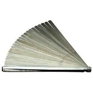
floridas hardly the ideal climate for keeping tools rust free so i generally take my set of micrometers out of the storage case and open and close them and spray them down with a light oil like WD 40 and place them back in the box then place the whole box in a 2 gallon zip lock bag in a shallow tupper ware type air tight storage box that is just the size to fit inside one of your tool chest drawers too protect the precision measuring tools , feeler gauges and plasti-gauge youll need to measure clearances correctly.when not in use along with the dial calipers.
micrometerset.jpg


http://garage.grumpysperformance.com/index.php?threads/bearing-clearances.2726/

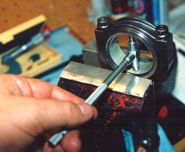
the reason I bring this up is I recently was over at a friends house where I needed to accurately measure a u-joint bearing cap and asked if he had a micrometer or dial caliper, he responded he had a very expensive looking imported micrometer, he had acquired recently at an estate yard sale for $30,
starl.png

when he opened the very impressive looking brass and mahogany box the micrometer, inside was a solid rusted mass, I soaked it in marvel mystery oil and acetone mix for 30 minutes then gradually worked it loose and polished it up with 1500 grit wet/dry sand paper figuring no loss at this point and was amazed that after about 30 minutes of constant cleaning it not only looked fairly decent it seemed to read accurately on a test gauge so I think it was mostly ugly surface rust, but it sure looked horrible, and to someone who appreciates good tools,that was depressing.

btw look around at yard sales and estate sales every so often youll find amazing bargains in used precision tools
yes it sure helps to have the correct tools and know where to measure parts


pistondie.png

dcp3.jpg

pistondiam.jpg

dialborega.png

http://www.tooltopia.com/fowler-72-646-300.aspx
555-81630.jpg

16336.jpg

http://www.harborfreight.com/3-piece-micrometer-set-66512.html
1319.jpg

http://www.harborfreight.com/12-inch-di ... 47261.html
IVE got a wide selection of MICS and Calipers and IVE checked the cheap Chinese crap measurements and consistency against the much more expensive Japanese and American tools and surprisingly most are consistent , and reasonably accurate and decent quality if you get the stainless steel tools
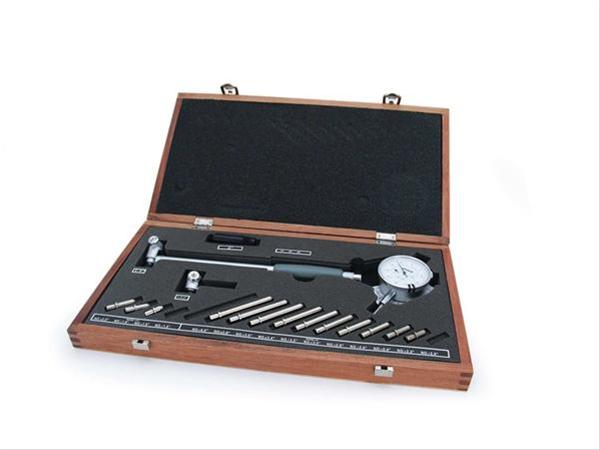
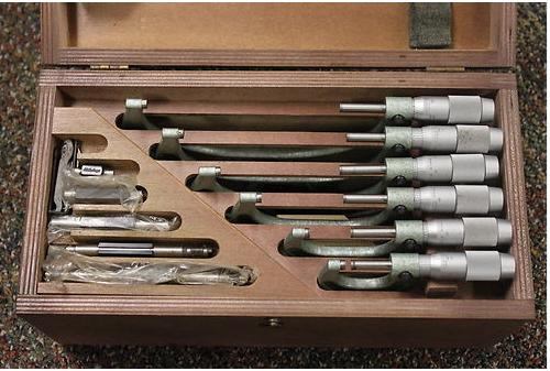
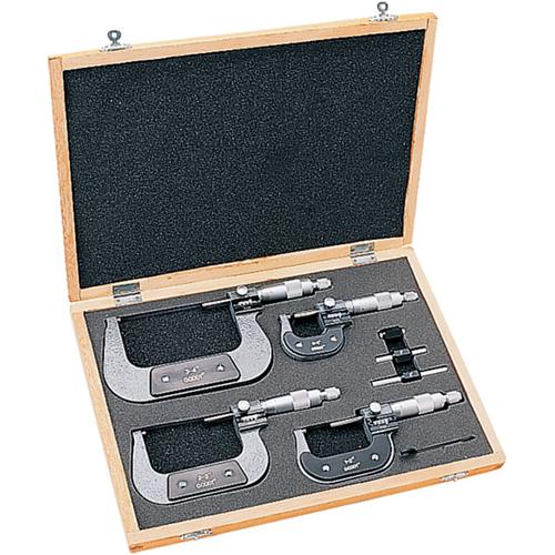
Mitutoyo, makes a good set that Ive had for years ( I bought a used set similar to the picture below, cheap at a yard sale, for $150 )
micrometerset.jpg

clearance1r.jpg

clearance2r.jpg

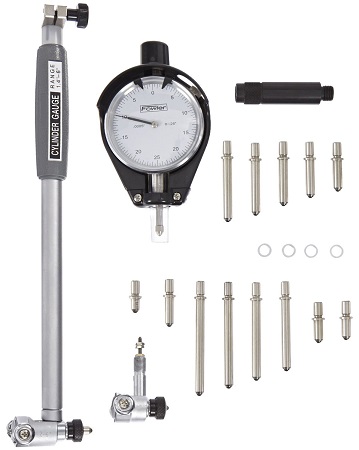
heres a cheap chinese import set, Ive used, a a friends house that work ok
http://grizzly.com/products/G5632

http://grizzly.com/products/2-6-Dial-Bore-Gage-Set/T24793

g5632.jpg

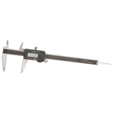
Ive found that a decent set of snap gauges and mics and a decent digital caliper will allow you to get bye quite nicely when used with some other checking tools, like plasti-gauge. repeatability and consistency are important.
plasti-gauge is an excellent cross check tool, easy to use and accurate, if used correctly, and I would not be a bit concerned if thats all you had to check bearing clearances, I use a fairly expensive set of mics, and snap gauges but I always cross check with plasti-gauge, and you ll be surprised at how accurate its really is

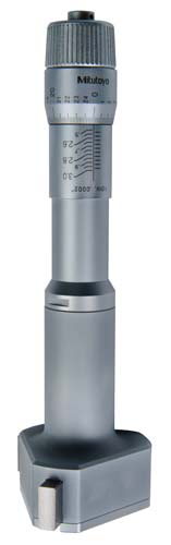
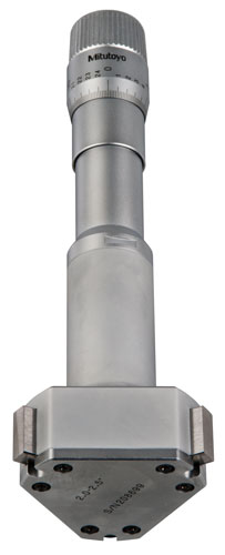
http://ecatalog.mitutoyo.com/Holtest-Ty ... C1530.aspx
368-871.jpg

368-870.jpg


even the cheapest Chinese tools are usually adequate if you know what your doing, and are only using them occasionally and take care in carefully measuring components, and you verify with plasti Gage ,feeler gauges, and your consistent and take care during assembly
(SURELY NOT IDEAL BUT FULLY USABLE, frankly IM amazed at the cheap tool accuracy levels) I think a good deal of the reason is that once your down to clearances of a 1/2 thousand or less a few ten thousands difference are less a concern to durability than consistency and care taken in assembly and clearencing, and polishing, or smoothing parts

you'll need check standards to verify accuracy before each use, and you must keep the standards remain rust free in zip loc bags with a fine coat of wd40

it certainly helps to have a few tools that measure accurately

StretchGauges2.jpg


heres some info from napa
http://knowhow.napaonline.com/know-notes-measure-engine-bearing-clearance/
bearing_clearance_feature.jpg

KNOW-HOW NOTES: HOW TO MEASURE ENGINE BEARING CLEARANCE


When rebuilding an engine, there is nothing more critical than getting the bearing clearance correct. Every engine has its own bearing clearance specs, but the measuring procedure does not change. There are two main methods used for checking bearing clearance – Plastigage® or gauges.

Plastigage®
Plastigage® has its place, as it serves a purpose for backing up and verifying your bearing clearances. Plastigage® is a special plastic that expands a specific amount when squeezed. Sold in sleeves of threads for specific thickness ranges, Plastigage® works really well in situations where the components are not being completely removed, such as in-engine bearing replacement, and other non-automotive uses. Originally put on sale in 1948, Plastigage® is fairly accurate and the method of choice for many DIY enthusiasts.

IMG_7335a.jpg

Plastigage® is quite useful, so don’t automatically throw it out. It is a good way of verifying your measurements.

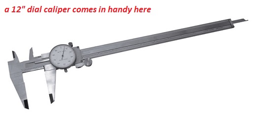
In reality, the right way to check bearing clearances is with the proper tools. In order to check the clearances for rod and main bearings, you need a set of micrometers and a dial-bore gauge. These are readily available at budget prices, but if you are going to use them a lot, better quality tools are advised.
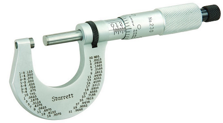
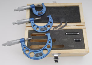
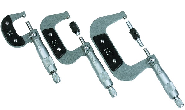
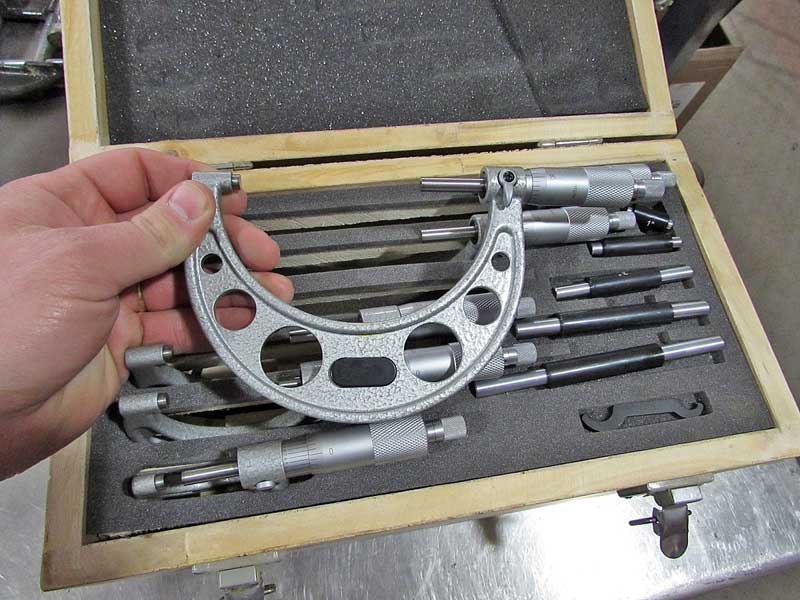
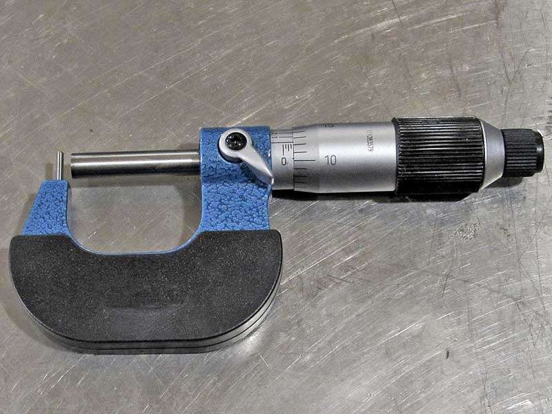
Micrometer
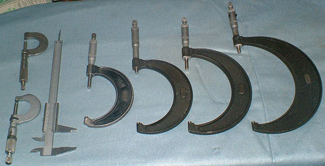
This looks like a horseshoe with a round handle attached to one leg. Micrometers typically only adjust 1”, so you need multiple sizes to get the job done. A 1-6” set usually has the sizes you need for most jobs.

IMG_6558a.jpg

This a complete micrometer set that will cover just about anything you could need for automotive work.
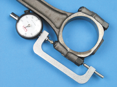
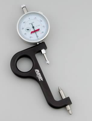
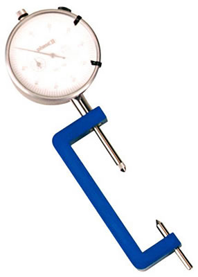
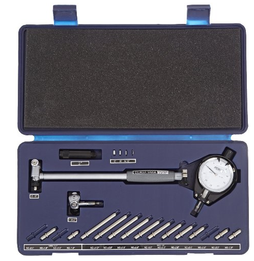
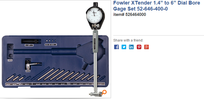
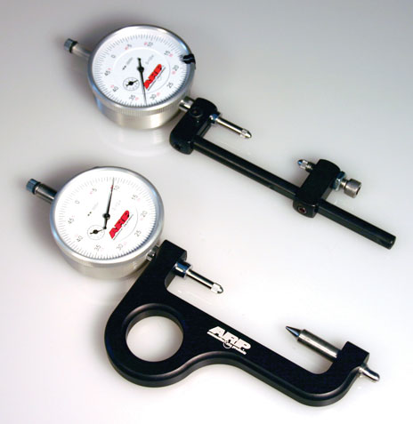
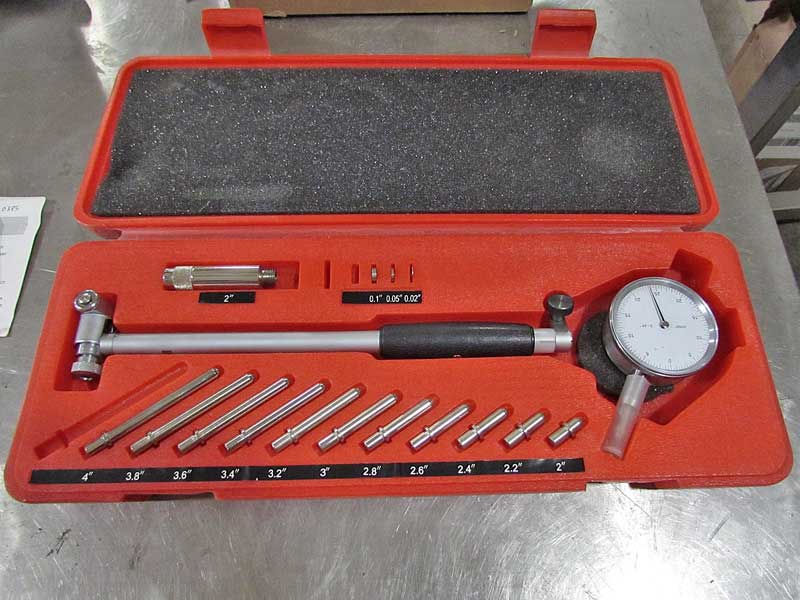
Dial-Bore Gauge
This tool uses a dial indicator on a post with a small wheeled measuring apparatus. These are adjustable through graduated post extenders that increase the diameter of the measurement circle.

IMG_6564a.jpg

The dial bore gauge measures the inside of round holes, such as the bearing journals.

http://garage.grumpysperformance.com/index.php?threads/bare-minimum-tools.11026/#post-51843

IMG_6565a.jpg

This one tool can measure 2″ up to 6″ diameter holes.

Both tools are needed in order to check the interior and exterior dimensions of the crankshaft, rods and engine block journals, as well as the thickness of the bearings themselves. Making all of this happen can be tricky, so here are a few tips to help you work through the process.

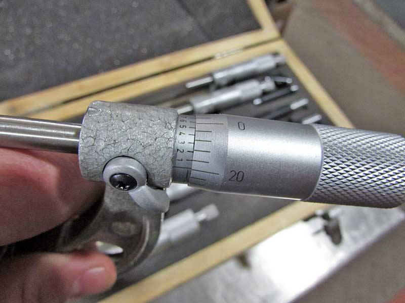
Using a micrometer means following a couple of rules. The key to a micrometer is not to tighten it too much. There are two knobs – a large knob and then a smaller one. The smaller knob clicks when the micrometer is in contract with the part. DO NOT use the larger knob to tighten the mic onto the part as this can damage the tool.

Reading a micrometer can be confusing, they are graduated differently than rulers. The inside barrel is marked in .100” (large) and .025” (small) notations. Once you reach those marks, the scale on the thimble (large rotating knob) comes into play to get the finite measurements. The thimble is scaled in .001 divisions from .000 up to .025”.

IMG_6562a.jpg

The hash marks are how you read micrometers. It takes some practice, and unless you use them daily, you will forget over time. Just be patient.

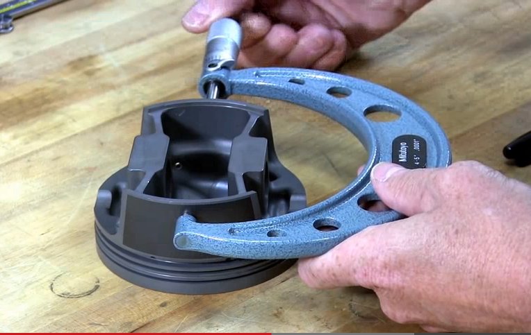
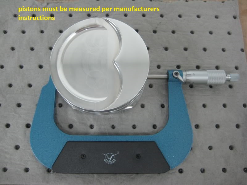
Outer Diameter Measurements
These are fairly simple, just choose the micrometer that covers the range needed and measure. It is a good idea to check the part in three different locations, staying away from the oiling holes as they can throw off the measurements due to the chamfers.
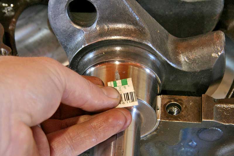
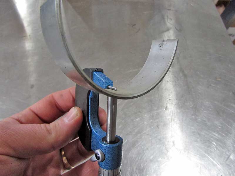
Measuring Bearings
Even though bearings are flat enough, they cannot be accurately measured with calipers, instead you need a micrometer. There are special micrometers available for measuring round inside surfaces, but you don’t have to have one of those. Instead, you can use the shaft of a drill bit (good quality, and use the smooth part, not the fluted section). Place the drill bit on the inside curve, and then measure the bearing. Subtract the thickness of the drill bit (measure, don’t assume), and you will have the thickness of the bearing.

IMG_6571a.jpg

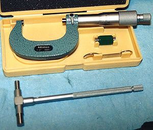
An tube mic is useful for measuring bearings and over inside-curved pieces. In a pinch, you can use a drill bit or pushrod and an outside mic.


IMG_6576a.jpg

This is how bearings are measured. DO NOT use calipers, you can easily scratch the babbit material and ruin the bearing, plus they are just not accurate enough.

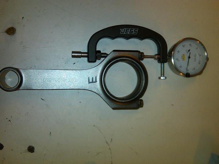
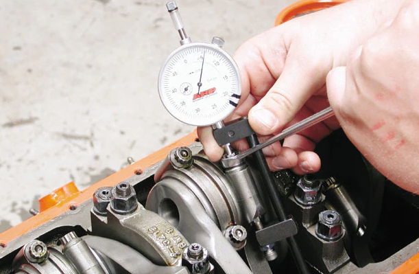
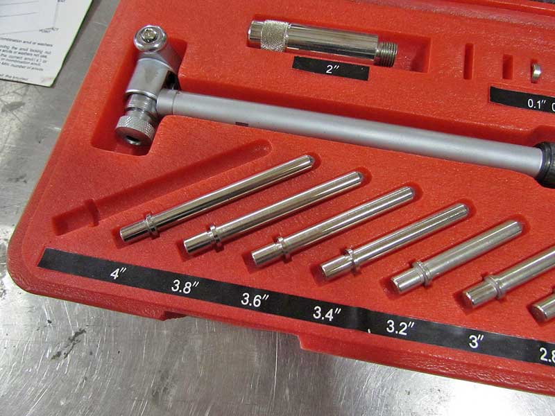
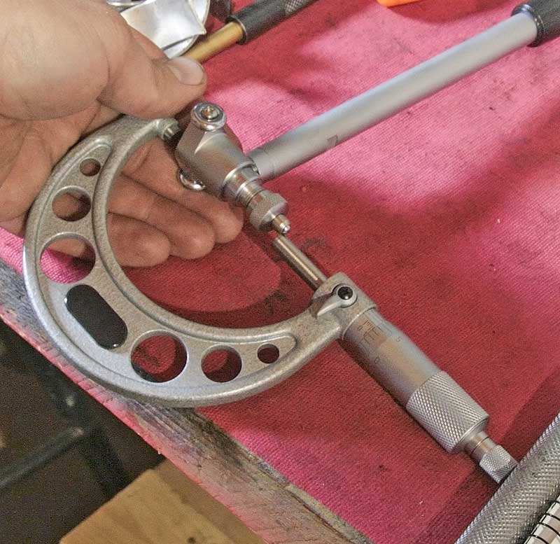
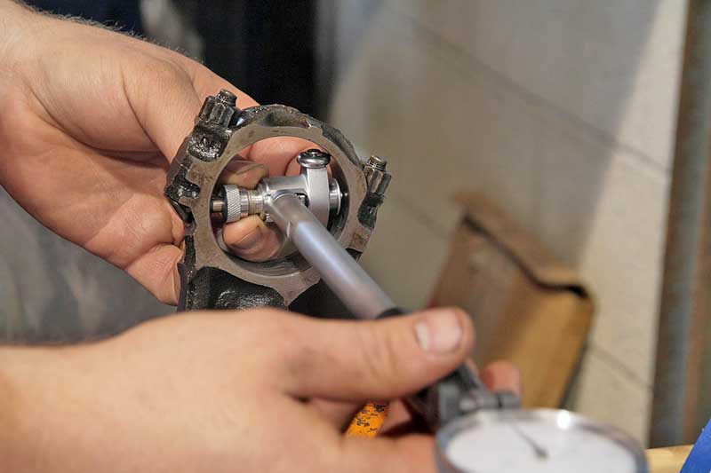
Using A Dial-Bore Gauge
Setting up a dial-bore gauge requires using a micrometer. You need the base measurement of the bore, rough is enough. Set the gauge to just over the diameter, using the correct extensions. Set the micrometer to the bore size you need, then place the gauge between inside the mic and rock the gauge back and forth, and side to side. Note the minimum reading, and zero the gauge to that reading.

crop-1a.jpg

Setting the dial bore gauge uses both the bore gauge and a micrometer. Make sure the measuring ends are square inside the micrometer’s anvils (not as shown)

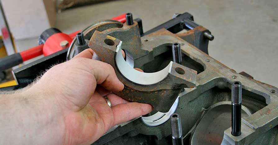
Inside Diameter Measurements
With the dial-bore gauge set to the correct size, place the gauge inside the journal or rod end and rock the gauge back and forth and side to side, just like the setup process. Note the smallest diameter, that is the size of the journal. Just like the outside measurements, take the reading in three different places. One note – the bore must be as it would be in use, so torque the caps to their correct specs and they need to be clean, no oil at all.

IMG_5607a.jpg

Place the gauge inside the journal and move it slowly till you find the largest measurement. Take readings in three places.

checking standards
READ THRU THE LINKS AND SUB LINKS
or youll miss a great deal of related useful info


viewtopic.php?f=59&t=1026&p=4327&hilit=plasti+gauge#p4327

viewtopic.php?f=50&t=3157&p=8449#p8449

http://www.medfordtools.com/metalworking/123blocks.html

http://mechdb.com/index.php/Plastigagin ... clearances

http://arp-bolts.com/p/instructions.php

http://www.qualitymag.com/CDA/Archives/ ... 32a8c0____

https://www.travers.com/htdocs/pdf/0744cat.pdf

most micrometer sets come with check standards,but youll generally want a few extra sized ones, its important that you verify accuracy with them, remember heat expands metal, don,t expect parts that are warm to measure the same when its cool

http://www.wikihow.com/Use-and-Read-an- ... Micrometer

http://www.worldtools.com/tools/precisi ... p-971.html


http://video.google.com/videosearch?oe= ... Q&start=20


http://www.harborfreight.com/cpi/ctaf/d ... mber=97389

http://www.harborfreight.com/cpi/ctaf/d ... mber=66512

http://www.harborfreight.com/cpi/ctaf/d ... umber=5649

http://www.harborfreight.com/cpi/ctaf/d ... mber=32214

http://www.jegs.com/i/Mopar+Performance ... 9/10002/-1


http://www.amazon.com/dp/B000HDF8N4/ref ... nkCode=asn
 
Last edited by a moderator:
just wondering , how many of you gentlemen are like I am,
and have taken to keeping a spare set of 275/300 power, reading glasses ,
you pick up from the local dollar store for $1.50 each
300gl.jpg

(I buy several every time I visit and leave a few in the tool box)
and around the shop, and my computer desk,
to read fine print on prescription bottles, component install instructions,
and simply so I can read the dial indicator,
torque wrench, caliper's , micrometers, bore gauges, and similar tools,
and look over the condition of parts, etc,
its AMAZING how much clearer the fine surface finish,
on parts your working on, is,
and fine print is once you have access to clear vision and bright lighting

Ive also found I can use a handy portable light.

biglarry.jpg


https://www.enginelabs.com/engine-tech/blueprint-series-measuring-and-setting-bearing-clearances/

https://www.zoro.com/fowler-dial-bore-gage-set-526463000/i/G0059624/?recommended=true


https://www.amazon.com/Nebo-Big-Lar...ocphy=9012039&hvtargid=pla-422733965918&psc=1
 
Last edited:
Back
Top