now think it thru,
(1)pressure is the resistance to oil flow
(2) the high voluum pump can push about 25% more oil
(3) the oil pump bye-pass circuit limits the max pressure in either size pump to about 65lbs-75 lbs MAXIMUM before it BYE-PASSES all additional oil voluum back to the low pressure side of the pump impellers in the pump.
(4) the engine can accept and use only the max flow voluum that the engine passages can flow at the max pressure the pump provides , at any point less than max pressure the passages can flow only what the pressure and voluum provided by the pump supplies
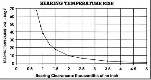
(5)if the bearing clearances can flow more than the pump provides in voluum and pressure at any rpm level the film of cooling oil that provides a cushion between the bearing surfaces are at risk of not being supported and seperated by that cushion of oil
(6) now since the sweep voluum is greater with the high voluum pump it will reach that bye-pass circuits max pressure at about 25% lower rpms and supply a POTENTIALLY higher voluum of oil to the supply passages/bearings
(7)SO... all a high voluum pump does is provide the maximum oil flow the engine can use up to the max pressure allowed by the bye-pass circuit at a 25% lower rpm level if the system can reach max pressure, but it also supplies 25% more oil at every rpm level below that point to provide additional cooling and protection for the engine. and if the engine can flow more than the stock pump can provide the high voluum pump helps fill the need faster
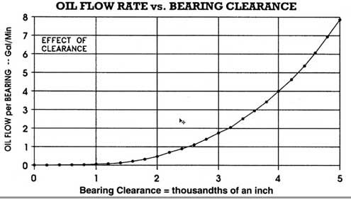
(8)oil flow through the bearing clearances INCREASES at a faster rate as the rpms increase
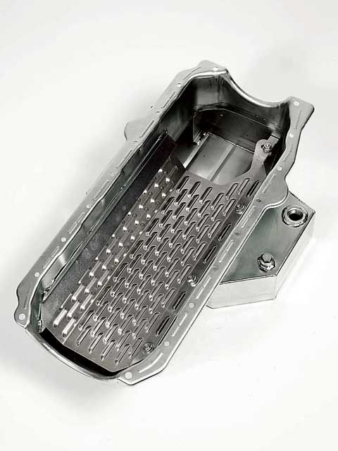
(9) in most engines the oil flow can be provided by the stock pump IF the clearances are close to stock AND THE RPM LEVELS ARE KEPT IN ABOUT THE idle-6000rpm range but if rpm levels exceed ABOUT 6000rpm,or if bearing loads greatly exceed the stock hp levels, or the clearances are greater than stock, the high volume pump is a good idea , simply because it potentially provides that extra volume of oil. its generally a BAD idea to install a high volume oil pump without a high volume baffeled oil pan to match the oil pump potential, that will feed the higher oil flow and a windage screen that returns the oil to the sump more effiently
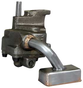
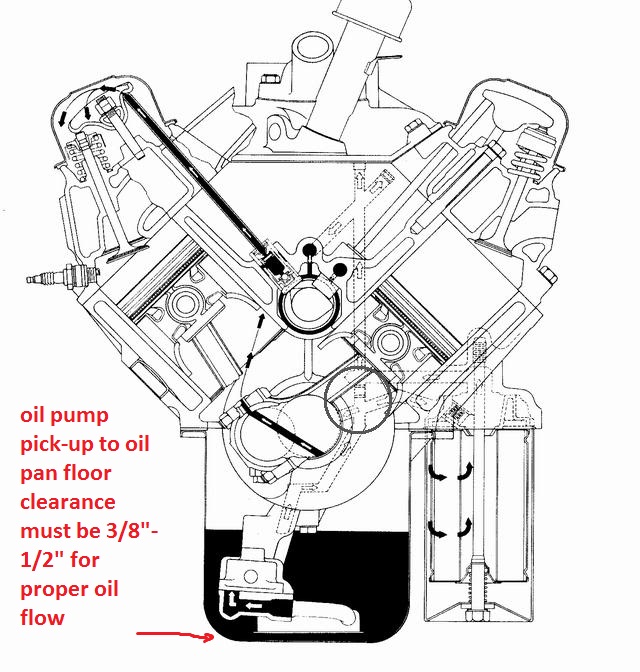
any less than about a 1/4" between the oil pan pick-up and the pan floor tends to restrict oil flow into the pick-up on many oil pump pick-up pan combo designs and more than about 3/8" to about 1/2 MAX tends to allow air to be sucked under some hard brakeing or accelleration with some pan and pick up designs so a 3/8"-1/2" pick-up to pan floor clearance is what I tend to try for, Ive seen numerious cases where a high voluum pump was installed without checking the clearances (and of course the pick-up moved closer to the oil pan floor simply because the oil pump itself is longer and the pick ups deeper in the pan if its reused from the old pump)and the engine SEEMED to run out of oil pressure almost instantly on accelleration, (im sure this is what leads to the myth of pumping the pan dry, but simply swapping pick-ups and verifying the pan floor to pick-up clearances cured the lack of oil flow into the pump and restriction that was the true cause of the low oil pressure condition. you should also remember that high volume oil pumps are designed for high flow rates, something best achieved with the thinner 10w 30 weight oils.
remember the high voluum pumps have a deeper body to fit the longer impeller gears. this places the oil pump pickup closer to the oil pan floor if no other changes are made when swapping to a high voluum pump from the standard pump and can restrict oil flow into the pump
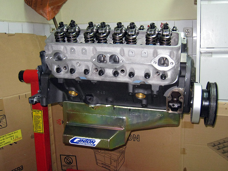
if you choose to install a high volume oil pump you should SERIOUSLY consider the fact that the pump is only a small part of the whole oil system,(which includes a high volume BAFFLED oil pan (7qts or more is ideal) and a windage screen, which is necessary to quickly return that extra oil to the sump, and doing the distributor mod is a big help, as it prevents any potential for cam/gear wear (something already almost non-existent with synthetic oil and the proper distributor gear material.)
the bye-pass spring only limits the pressure at which the bye-pass OPENS thus it only effects the upper pressure limit and has NOTHING to do with oil pressures or flow BELOW that level
BTW heres an old post that will answer several questions
I just got asked
" I just installed a new oil pump and have no oil pressure over about 1500rpm. but IM pulling about 24 psi at IDLE?? whats wrong GRUMPY"
the oil pick-up needs to be mounted between 3/8-1/2" from the oil pan floor.MOUNT THE PUMPS INTAKE TOO CLOSE TOO THE PAN FLOOR AND YOULL GET THE RESULTS YOUR SEEING! THE reason is that at low rpms the pumps pick-up can feed enought oil but speed up the pump, the flow requirement goes up and since the pick-up can,t supply the pumps needs, it cavitates and oil pressure falls rapidly to near ZERO ..untill the rpms drop back to the point where the pick-up CAN supply the pumps needs
HERES MORE OIL INFO
small block oil pumps generally but not in all cases have 5/8" pickup tube dia. while BIG blocks generally but not in all cases have 3/4" pickup tube dia.
keep in mind that in many cases the big block pump can be bolted onto and used on the small block engine (a comon mod) and that you need to carefully check clearances on the oil pump,oil pump drive shaft to distributor length and pan to pickup clearances in all oil pump installations
braze the pick-up tube to the pump body so the pick up is 3/8" MINIMUM, 1/2" maximum from the oil pan floor and use a large lump of MODELING CLAY (every mechanic should have some its great for checking clearances)on the pickup then install the pan temp. with no gasket and remove to measure the thickness of the clay
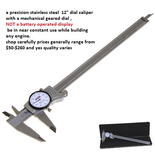
your local arts/craft store sells it in 1 lb blocks I usually use brite blue or black but suit your self, a digital caliper or even a ruler will get you the thickness measurement your looking for)
MOST CRAFT STORES SELL MODELING CLAY
once its correctly possitioned ,remove the bye pass spring and gears from the oil pump,and have the pick-up brazeD or welded to the pump body, then after it SLOWLY AIR cools (DON,T DROP IT IN WATER LET IT AIR COOL)replace the byepass spring and gears, lube the pump,with assembly lube on the gears, check the clearances, check clearances again! and install! just be damn sure its brazed or welded in the correct location as that 3/8"-1/2" is critical to good oil voluum feeding the pick-up
http://users.erols.com/jyavins/solder.htm«
http://www.tinmantech.com/html/faq_b...soldering.html
http://www.epemag.wimborne.co.uk/solderfaq.htm
silver soldering is basically lower temp brazeing , the soldering metal flows over the surface and into micro cracks in the surace of the other metal forming a almost unremoveable bond to the other metals surface it allows you to stick iron to steel or brass to steel, it works more or less like normal solder does on copper but at higher temps and has a much stronger grip in addition too working on iron and steel
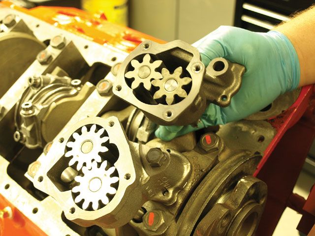
I vastly prefer the 5 BOLT BBC style pumps with the 12 tooth gears and thier larger 3/4" pick-up VS the small 4 bolt pumps with thier 5/8" pick-ups and 7 tooth gears. the oil flow is both higher pressure at low rpms and smoother in pulse presure spread,no! you don,t need it on a non-race combo, or even on some race combos but its nice to have and I willingly will loose a few hp pumping oil for better engine lubracation
most comon question I get? "will a high volume oil pump help or hurt my engine?" followed by some guy saying
"If you're using a stock capacity pan, the high volume oil pump could actually suck out all the oil from the pan before it is drained back in, thus creating bad, bad problems"
absolutely proven false bye SMOKE YUNICK with HIGH SPEED PHOTOGRATPHY and CLEAR WINDOWS IN ROCKER COVERS AND OIL PANbut what can and does happen is the oil pump pickup can and does get mounted or moved too high or low in the oil pan,restricting access to the oil supply, sometimes the pickup comes loose or under hard acceleration or brakeing the oil in a non-baffled pan can rush away from the pickup under (G) forces, this is not pumping the pan dry, a baffled pan with a windage screen with the same oil supply volume would work perfectly
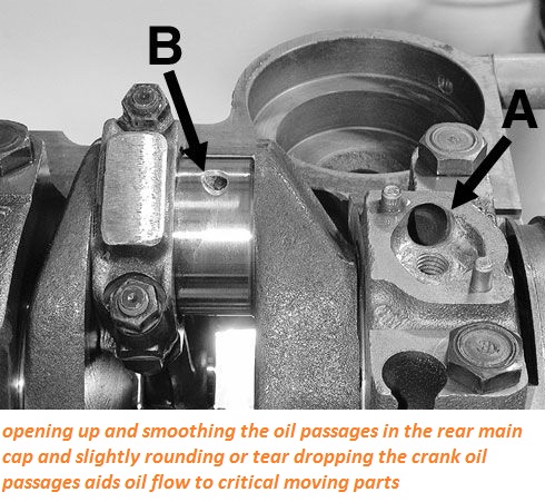
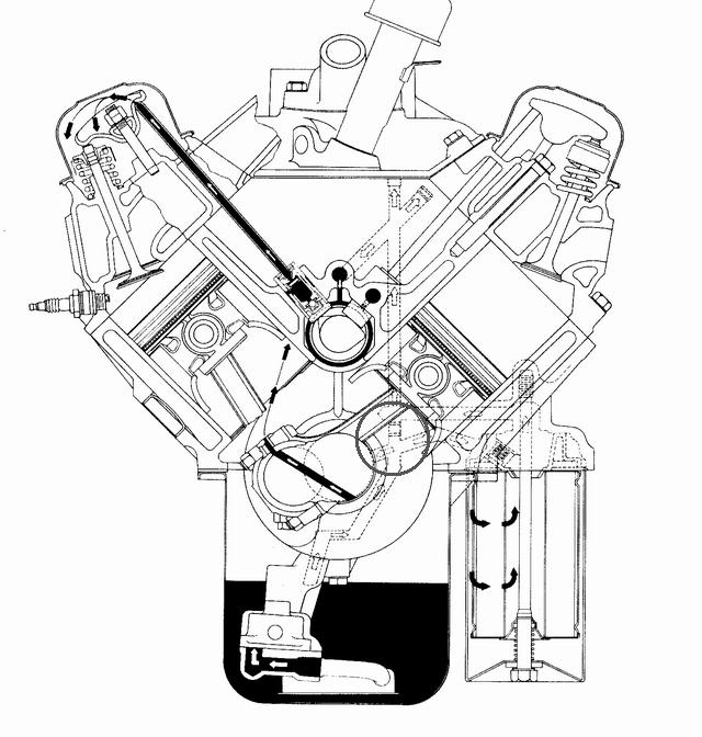
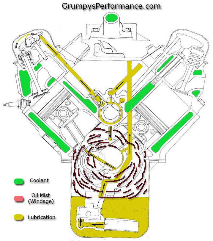
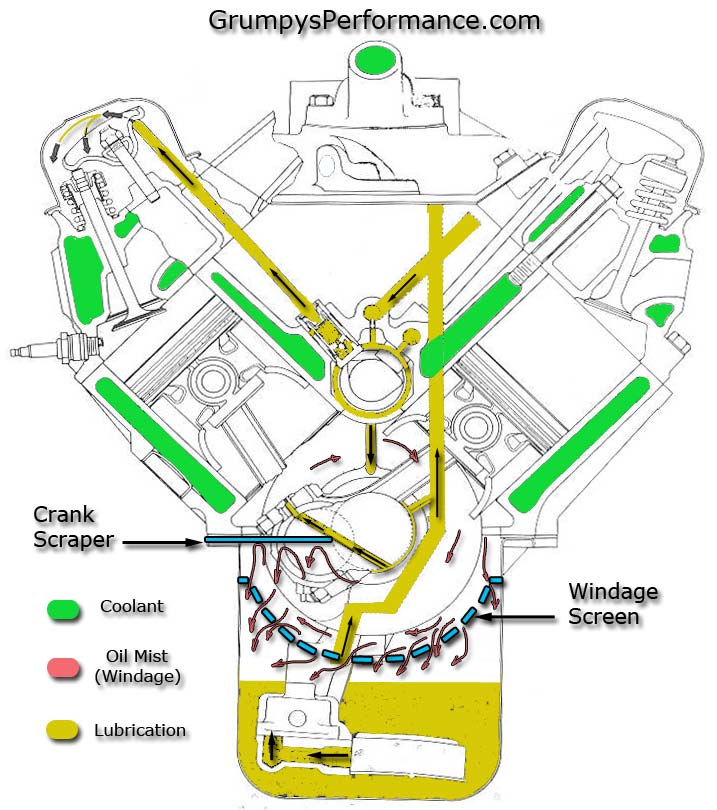
ok lets look at a few things, pressure is the result of a resistance to flow , no matter how much oil is put out by the oil pump there is almost no pressure unless there is a resistance to that oil flow and the main resistance is from oil trying to flow through the bearing surface clearances and once the pumps output pressure exceeds the engines ability to accept the oilflow at the max pressure the oil return system/bypass spring allows the oil circles back through the pump ,now the amount of oil flow necessary to reach the furthest parts in the engine from the oil pump does not go up in direct relation to rpm, but it instead increases with rpm at a steadly increaseing rate that increases faster than the engine rpm due to centrifugal force draining the oil from the rods as they swing faster and faster since energy increases with the square of the velocity the rate of oil use goes up quite a bit faster due to the greatly increased (G-FORCES) pulling oil from the rod bearings over 5000rpm going to 8000rpm than the rate of oil flow increases from 2000 rpm to 5000rpm (the same 3000rpm spread) and remember the often stated (10 lbs per 1000rpm)needs to be measured at the furthest rod and main bearing from the pump not at the pump itself, next lets look at the oil flow itself, you have about 5-6 quarts in an average small block now the valve covers never get and hold more than about 1/3 to 2/3 of a quart each even at 8000 rpm (high speed photography by SMOKEY YUNICK doing stock car engine research with clear plastic valve covers prove that from what Ive read) theres about 1 quart in the lifter gallery at max and theres about 1 quart in the filter and in the oil passages in the block, that leaves at least 2 quarts in the pan at all times and for those that want to tell me about oil wrapped around the crankshaft at high rpms try squirting oil on a spinning surface doing even 2000rpm (yes thats right its thrown off as fast as it hits by centrifugal force, yes its possiable for the crankshaft WITHOUT A WINDAGE SCREEN to keep acting like a propeler and pulling oil around with it in the crank case but thats what the wrap around style milodon type windage screen is designed to stop)the only way to run out of oil is to start with less than 4 quarts or to plug the oil return passages in the lifter gallery with sludge or gasket material! now add a good windage tray and a crank scrapper and almost all the oil is returned to the sump as it enters the area of the spinning crankshaft! forming a more or less endless supply to the oil pump, BTW almost all pro teams now use DRY SUMP SYSTEMS WITH POSITIVE DISPLACEMENT GERATOR PUMPS that are 3,4,or 5 stage pumps each section of which has more voluum than a standard voluum oil pump because its been found total oil control is necessary at high rpms to keep bearings cool and lubed
NOW I POSTED THIS BEFORE BUT IT NEEDs REPEATING
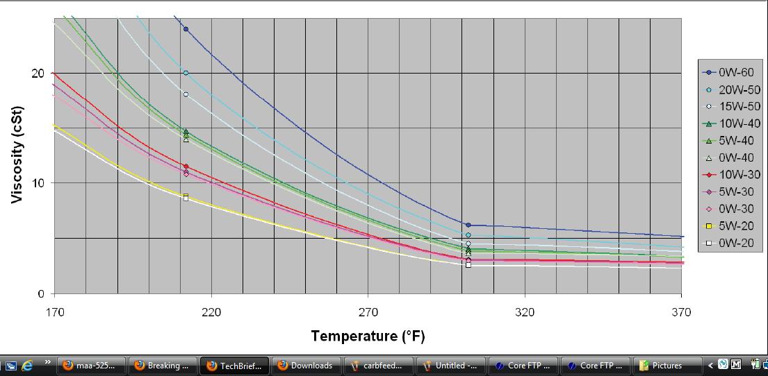
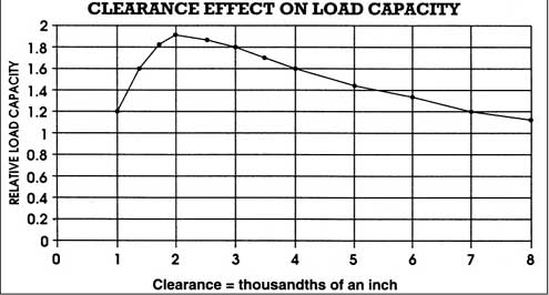
ok look at it this way,what your trying to do here is keep an pressureized oil film on the surface of all the bearings to lube and cool them and have enough oil spraying from the rod and main bearing clearances to lube the cam and cylinder walls/rings. now a standard pump does a good job up to 5000rpm and 400 hp but above 6000rpm and 400hp the bearings are under more stress and need more oilflow to cool and because the pressure on the bearings is greater you need higher pressures to maintain that oilfilm.lets look at the flow verus pressure curve. keep this in mind, good oil flow volume across the bearing surfaces to cool and luberacate them and to provide a boundry layer between the metal surfaces is more important than the pressure reached at all rpms. since oil is a liquid its non-compressable and flow will increase with rpm up to the point where the bypass circuit starts to re-route the excess flow at the point were the pressure exceeds the bypass spring pressure. but the voluum will be equal to the pumps sweep voluum times the rpm of the pump, since the high voluum pump has a sweep voluum 1.3-1.5 times the standard pump voluum it will push 1.3-1.5 times the voluum of oil up to the bypass cicuit cut in point,that means that since the engine bearings leakage rate increases faster as the rpms increase because the clearances don,t change but the bleed off rate does that the amount of oil and the pressure that it is under will increase faster and reach the bypass circuit pressure faster with the high voluum pump. the advantage here is that the metal parts MUST be floated on that oil film to keep the metal parts from touching/wearing and the more leakage points the oil flows by the less the voluum of oil thats available for each leakage point beyond it and as the oil heats up it becomes easier to push through the clearences.now as the rpms and cylinder preasures increase in your goal to add power the loads trying to squeeze that oil out of those clearances also increase. ALL mods that increase power either increase rpms,cylinder preasures or reduce friction or mechanical losses. there are many oil leakage points(100) in a standard chevy engine.
16 lifter to push rod points
16 pushrod to rocker arm points
32 lifter bores 16 x 2 ends
10 main bearing edges
9 cam bearing edges
16 rod bearing edges
2 distributor shaft leaks
1 distributor shaft to shim above the cam gear(some engines that have an oil pressure feed distributor shaft bearing.)
so the more oil voluum the better.chevy did an excelent job in the design but as the stresses increase the cooling voluum of the extra oil available from the larger pump helps to prevent lubracation delivery failure, do you need a better pump below 5000rpm or 400hp (hell no! at that level the stock pump works fine) above that level the extra oil will definitely helppossiable deficient oil flow and bearing cooling and a simple increase in pressure does not provide a big increase in voluum that may be necessary to keep that oil film in the correct places at the correct voluum at all times.the stock system was designed for a 265cid engine in a passenger car turning a max of about 6000 rpm but only haveing the stress of under 300hp transmitted to the bearings, Im sure the orriginal designers never thought that the sbc or bbc would someday be asked to on occasion hold up to 450-800hp and 6000-8000 rpm. nore did they forsee valve springs that placed sometimes as much as 500lbs and up loads on the lifters and the use of over 9 to 1 compression ratios in the original design so the oil voluums and pressures necessary to cool those valve springs and bearings at those stress levels were never taken into account for that either , the stock pump works but was never designed for the loads and rpms that a modern engine hotrodded to over 450hp sees
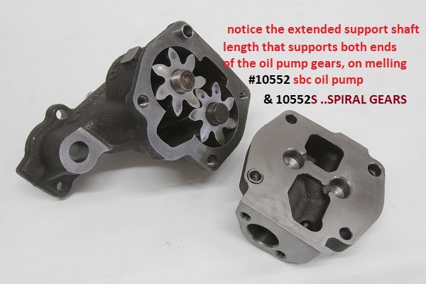
the standard volume pump gears are about 1.2" long the high volume pump gears are about 1.5 inches long (depends on manufacturer)
heres the discriptions right from chevy
12555884
SBC Oil Pump, High Pressure Z28/LT1. Production high-pressure oil pump with 1.20" gears.Will produce 60-70 psi oil pressure. Does not include screen. The pickup tube dia. is 5/8" for this pump.
62.17
14044872
SBC Oil Pump, High-Volume. This high-volume pump has1.50" long gears.It has approximately 25% more capacity than a production pump at standard pressure. Does not include screen.
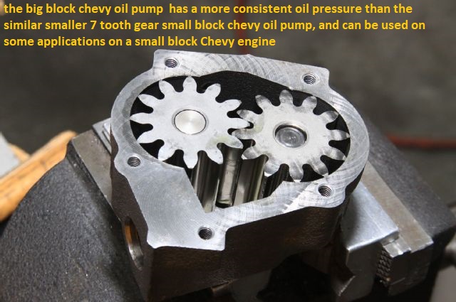
and yes I comonly build small blocks useing bbc oil pumps like the ls7 pump, it has 1.3" gears but they are bigger in dia. and have 12 not 7 teethlike the small block pumps (many standard sbc pickups use 5/8" dia. pickups) (the ls7 pump is best used on 8qt-9qt road racing oilpans as the larger 3/4" pickup flows lots of oil for extreme high rpm engines with a multi baffled pan useing windage screens, scrappers and cut outs for extreme (G) loads where a dry sump can,t be used or cost makes you stick to a wet sump pan. these LS7 pumps dont fit most sbc oil pans so your stuck using the high volume sbc oil pump if your not using a true racing 8-9 qt style oil pan in some cases
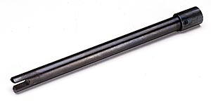
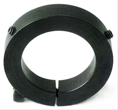
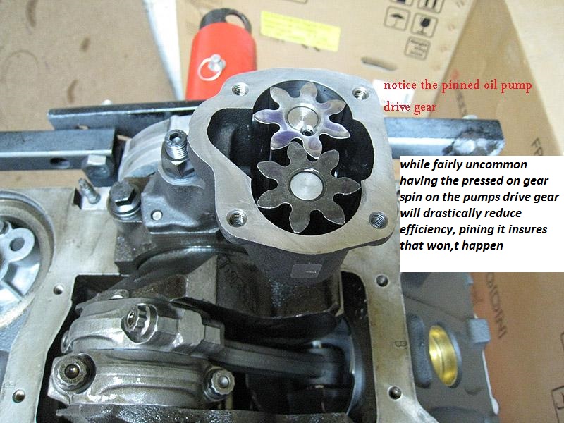
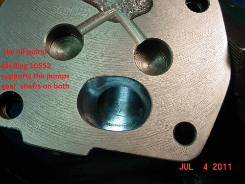
since I just got an E-MAIL about what mods are necessary or at least a good idea when running a high volume oil pump, and concern over possiable extra gear wear caused by the slightly and I do mean slightly increased pressure on the gears, guys Im getting the idea here that most of you are not aware that your normally suppose to cut a .060 wide x .005-9 deep grouve in the lower band on the distributor houseing so that extra oil sprays constantly on the contact point between the cam and distributor gears and that a ARP style drive shaft with a steel collar to hold the dirveshaft alignment on true center is mandatory for long high rpm use. look at this picture:
The grouve is cut under the bottom (O)ring in the band just above the gear (look at the picture above, (BTW the pic shows a smaller grouve than ideal)) and in line with the gears so that oil sprays on the gear contact points at all times, this is a mod most old time racers know about and use, but Im getting the idea the new guys have not picked up on it! (those two bands form the side of an oil passage in the block and the distributor shaft seals that passage, cutting the grouve sends a spray of high pressure oil onto the contact point at all times, if you dont cut the grouve your relieing on returning zero pressure oil flowing down the rear lifter gallery drain holes to lube the gears
BTW the other way to do this is to grouve the block in the distributors lower band area as this keeps the location of the oil jet constant as the distributor is turned, for a full contact spray on the gears so I generally do BOTH
btw
heres more OIL info
http://motorcycleinfo.calsci.com/Oils1.html
http://minimopar.knizefamily.net/oilfilterstudy.html
http://www.unofficialbmw.com/all/misc/all_oilfaq.html
http://www.bobistheoilguy.com/
http://www.babcox.com/editorial/ar/ar10180.htm
http://www.melling.com/support/bulletins/default.asp
http://www.melling.com/select/oil_pu...mall_block.asp
img]
http://www.sallee-chevrolet.com/Engine_Blocks/images/12480157.gif[/img]
one or at the most two of outer plugs for the oil passages plugs above the cam, drill a .030-.038 hole in one or both , naturally the one on the left is prefered as the rotation favors that side for spraying oil eveywhere under the timing cover
BTW DRILL the removed oil passage plugs, while they are clamped between a couple boards with a drill press If you can, you don,t want metalic shavings in the engine
don,t get too wrapped up in worring about which oil is superior, keep in mind oils main function is to provide a lubracating film and transfer absorbed heat,away from the moving parts, almost ANY of the name brand oils do that well and ALMOST ANY oil will last at least 5000 miles without significant loss of its abilities to do that if the filters used keep the particals in it minimized AND the temp stays in the 190F-250F range. but like I stated earlier, oil needs to get up to 215F at least for a short time to burn off moisture, and above about 240F it slowly brakes down, its the regular replacement with clean oil , to remove the crud from the engine and good filters thats the key!
EVEN if you had the best oil in the world, that could easily last 30K-35K miles the CRUD & acids trapped in the oil from cumbustion,would cause wear and reduce its lubration abilities over time, if the filters don,t remove the majority of that crud the oils life expectancy is limited reguardless of the oil quality itself , and regular replacement is the key
TWEAKING THE SYSTEM
since I just got an E-MAIL about what mods are necessary or at least a good idea when running a high volume oil pump, and concern over possiable extra gear wear caused by the slightly and I do mean slightly increased pressure on the gears, guys Im getting the idea here that most of you are not aware that your normally suppose to cut a .060 wide x .005-9 deep grouve in the lower band on the distributor houseing so that extra oil sprays constantly on the contact point between the cam and distributor gears and that a ARP style drive shaft with a steel collar to hold the dirveshaft alignment on true center is mandatory for long high rpm use. look at this picture:
The grouve is cut under the bottom (O)ring in the band just above the gear (look at the picture above, (BTW the pic shows a smaller grouve than ideal)) and in line with the gears so that oil sprays on the gear contact points at all times, this is a mod most old time racers know about and use, but Im getting the idea the new guys have not picked up on it! (those two bands form the side of an oil passage in the block and the distributor shaft seals that passage, cutting the grouve sends a spray of high pressure oil onto the contact point at all times, if you dont cut the grouve your relieing on returning zero pressure oil flowing down the rear lifter gallery drain holes to lube the gears
BTW the other way to do this is to grouve the block in the distributors lower band area as this keeps the location of the oil jet constant as the distributor is turned, for a full contact spray on the gears so I generally do BOTH
Mark a straight-ahead position on the outside of the distributor body to use as a reference mark for the distributors placement in the engine. Use this orientation to position the oil groove. Remember that the cam is on the drivers side of the distributor.
Crane suggests cutting a .030-inch-wide by .030-inch-deep slot in the lower band of the distributor housing to direct a spray of oil onto the camshaft and distributor gears. YOU can Use a Dremel tool to cut the slot into this distributor.
Thought I'd best add that you would be ahead by disassembling the distriburor first & clean the debris out before you re-assemble ,but you already know that
ITS just a tip for improving the oil flow to the distributor, GEARS TO PROMOTE LONGER LIFE,BUT it HELPS a good deal with cam/distributor gear life so its a STANDARD MOD I always do! (keep in mind youll want the grouve location to spray oil into the gear teeth contact area and that requires YOU to carefully match the notch location to the contact area WHEN the distributor is fully seated and timed correctly,
moving the distributor timing moves the oil spray pattern area so the time taken too CAREFULLY CUT a second shallow grouve in the block , on the lower band where the distributor seats and seal the oil passage as a secondary extra presureized oil spray source spraying oil onto the gear contact area,that can,t move seems like an even better IDEA . having twin high pressure oil jets spraying oil into the gears helps slow potential wear
Mark a straight-ahead position on the outside of the distributor body to use as a reference mark for the distributor’s placement in the engine. Use this orientation to position the oil groove. Remember that the cam is on the driver’s side of the distributor.
Crane suggests cutting a .030-inch-wide by .030-inch-deep slot in the lower band of the distributor housing to direct a spray of oil onto the camshaft and distributor gears. YOU can Use a Dremel tool to cut the slot into this distributor.
Thought I'd best add that you would be ahead by disassembling the distriburor first & clean the debris out before you re-assemble ,but you already know that
ITS just a tip for improving the oil flow to the distributor, GEARS TO PROMOTE LONGER LIFE,BUT it HELPS a good deal with cam/distributor gear life so its a STANDARD MOD I always do! (keep in mind youll want the grouve location to spray oil into the gear teeth contact area and that requires YOU to carefully match the notch location to the contact area WHEN the distributor is fully seated and timed correctly,
moving the distributor timing moves the oil spray pattern area so the time taken too CAREFULLY CUT a second shallow grouve in the block , on the lower band where the distributor seats and seal the oil passage as a secondary extra presureized oil spray source spraying oil onto the gear contact area,that can,t move seems like an even better IDEA . having twin high pressure oil jets spraying oil into the gears helps slow potential wear
one or at the most two of outer plugs for the oil passages plugs above the cam, drill a .030-.038 hole in one or both , naturally the one on the left is prefered as the rotation favors that side for spraying oil eveywhere under the timing cover
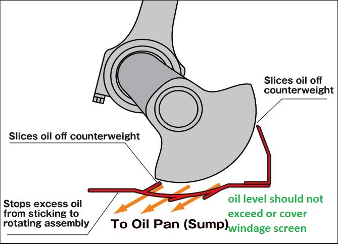
yes you can (and probably should) take the time to fabricate a windage screen similar too the one shown in the link above,
or in these link's
http://garage.grumpysperformance.com/index.php?threads/oil-system-mods-that-help.2187/
http://garage.grumpysperformance.com/index.php?threads/building-a-custom-wet-sump-oil-pan.65/
http://www.chevelles.com/techref/ScreenInstall.pdf
https://www.summitracing.com/parts/CTR-20-906/
http://garage.grumpysperformance.com/index.php?threads/whats-a-windage-tray-do.64/
http://garage.grumpysperformance.com/index.php?threads/custom-windage-tray.10490/
http://www.colemanracing.com/Windage-Screen-P3831.aspx
http://www.musclecardiy.com/performance/how-to-build-racing-engines-sumps-and-oiling/#
http://www.hotrod.com/articles/ctrp-0603-oil-pan-design-windage-tech/