TBucket 200-4R Transmission Project

Indycars

Administrator
Staff member

Ok this is where I go, "Oh shit....what the hell was I thinking!!! Why didn't I just keep the THM-350 transmission that I had."

Oh well it's too late for that now. The torque converter is here and the rest of my parts should be here next week. The torque converter has stall speed of 2800 RPM with these features you see below in the quote, cost was about $350.

http://www.extremeautomatics.com/
I first sent an email to Extreme Automatics but never received a reply.

http://www.ckperformance.com/index.html
So then I sent an email to Christoforos Kokkonis at CK Performance and got a reply back. A few days later I had a long conversation with Chris and decided on the parts that I needed. He suggested a kit with everything I needed including all the hard parts that I would need to upgrade, cost was about $900.


24RCSS2(D5): 12"STREET AND STRIP "D5" CONVERTER
THIS CONVERTER IS SPECIALLY BUILT FOR EXTREME DUTY STREET BUICK GRAND NATIONALS, HIGH OUTPUT MONTE CARLO SS’S, AND OTHER PERFORMANCE STREET/STRIP VEHICLES WHICH REQUIRE THE USE OF A 12" CONVERTER. THIS CONVERTER FEATURES A HEAVY DUTY LOCKUP CLUTCH, OVERSIZED TORRINGTON BEARINGS, BRAZED FINS AND A HARDENED HUB FOR IMPROVED DURABILITY IN HIGH LOAD APPLICATIONS. CONVERTER IS ALSO LEAK TESTED AND PRECISION BALANCED. APPROXIMATE STALL SPEED IS 2500-2800 RPM’S AND WILL HANDLE IN EXCESS OF 400 HORSEPOWER.


I got to put my new trans holding fixture to work last night. Should make the trans easy to work on, I can rotate it to most any position needed now. No wrestling with it only the bench or floor.


ViewOfLeftSide_2735.jpg
ViewOfValveBody01_2732.jpg
ViewOfValveBody02_2737.jpg
ViewOfVBFrontHalf_2744.jpg
ViewOfVBRearHalf01_2743.jpg

Just my luck, as I get started on this project, my consultant from Belgium went on a 4 week vacation! :D :p :D


Last edited:
busterrm said:
Hey Rick where are you on the Tranny?

Not moving very fast right now. I have the bottom end dis-assembled, the valve body is off but the valves are still in it.

I'm going out of town for a week or so, therefore I won't being getting much done for awhile.
 
please take a great deal of pictures, and let us know all you can during the transmission rebuild and upgrade, listing tools and parts used would be great, as far fewer guys know how to rebuild a 200r4 than know how to work on a first generation chevy V8.
keep in mind the transmission shift points and converter, stall speed, you want the converter stall to allow near instant access to the upper torque curve under full throttle, but you don,t want the engine needing to reve much above 4000rpm under light loads and part throttle, in an ideal world youll have a shift kit, and converter stall speed matched in that transmission, so under light throttle the engine rpms stay reasonably low and the trans shifts at lets say, 4200rpm, to the next higher gear, but under full throttle , the trans should shift several hundred rpm past peak horse power in the rpm range

http://www.autorepairmanuals.biz/site/5 ... 83-2004RTM

http://www.msgpio.com/manuals/mshift/V41tune.html

http://www.auto-repair-manuals.com/GM-T ... anual.html

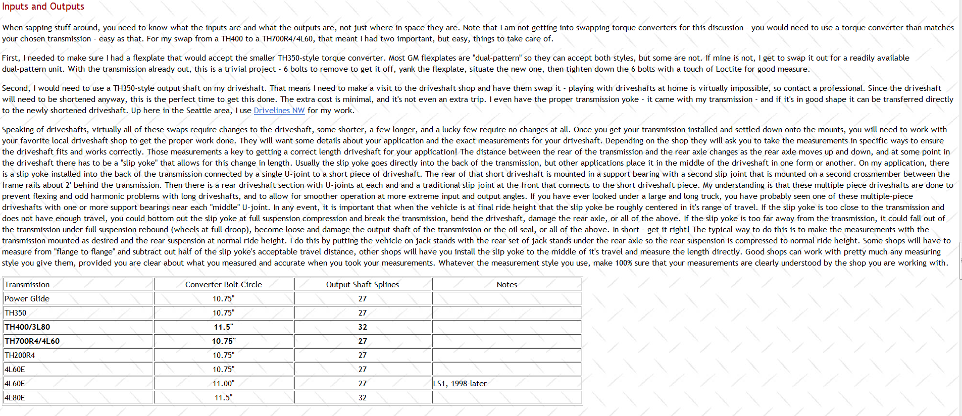
http://garage.grumpysperformance.co...g-a-performance-transmission.7082/#post-40015

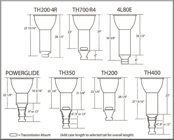
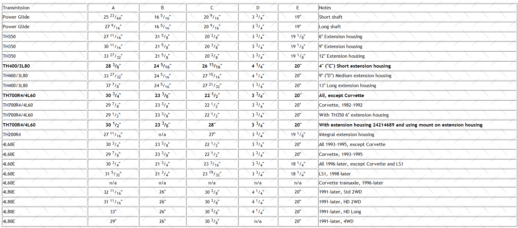
http://www.tciauto.com/tc/trans-dim/
Transmission Dimensions Chart.jpg

transwe6.gif

transwe3.png

transwe4.png

http://www.monstertransmission.com/GM-Transmissions_c_4314.html

http://2004r.net/

http://web.archive.org/web/200701300142 ... rebld.html

http://web.archive.org/web/200701281733 ... 2004r.html

http://web.archive.org/web/200701251259 ... tches.html

http://web.archive.org/web/200704201144 ... enoid.html

200r4 trans codes
1984 - 4CQ
1985 - 5CQ
1986 - 6CZ
1987 - 7CZ
1988 - 8CZ
http://www.makcotransmissionparts.com/200-4r.html

List of GM transmissions
From Wikipedia, the free encyclopedia


Jump to navigationJump to search
General Motors is an innovator of automatic transmissions, introducing the Hydra-Matic in 1940.[1] This list includes some GM transmissions.

Contents
Automatic transmissions[edit]
Early models[edit]
The GM Hydra-Matic was a success and installed in the majority of GM models by 1950. Through the 1950s, all makers were working on their own automatic transmission, with four more developed inside GM alone. All of GM's early automatic transmissions were replaced by variants of the Turbo-Hydramatic by the 1970s.

Turbo-Hydramatic[edit]
The Turbo-Hydramatic was used by all GM divisions, and formed the basis for the company's modern Hydramatic line. The basic rear-wheel drive Turbo-Hydramatic spawned two front-wheel drive variants, the transverse Turbo-Hydramatic 125, and the longitudinal Turbo-Hydramatic 425. A third variant was the light-duty rear wheel drive Turbo-Hydramatic 180 used in many European models.

Heavy-duty rear wheel drive
  • 1971–1994 3L80HD (heavy duty version of TH400)
Medium-duty rear wheel drive
Light-duty rear wheel drive
  • 1969–1998 TH180/TH180C/3L30 — 3-speed European/Asian model. Also manufactured and used by Holden as the Trimatic transmission.
Transverse front wheel drive
Longitudinal front wheel drive
  • 1966–1978 TH425 — 3-speed
  • 1979–1981 TH325 — 3-speed
  • 1982–1985 TH325-4L — 4-speed
Electronic Hydra-Matics[edit]
The next-generation transmissions, introduced in the early 1990s, were the electronic Hydra-Matics based on the Turbo-Hydramatic design. Most early electronic transmissions use the "-E" designator to differentiate them from their non-electronic cousins, but this has been dropped on transmissions with no mechanical version like the new GM 6L80 transmission.

Today, GM uses a simple naming scheme for their transmissions, with the "Hydra-Matic" name used on most automatics across all divisions.

3/4/5/6 L/T ## -Elll
Number of forward gears L=Longitudinal
T=Transverse GVWR rating "E" for Electronic
"HD" for Heavy Duty
First-generation longitudinal (Rear Wheel drive)
  • 1991–2001 4L30-E — 4-speed light-duty (used in BMW, Cadillac, Isuzu, and Opel cars)
  • 1992– 4L60-E/4L65-E — 4-speed medium-duty (used in GM trucks and rear-wheel-drive cars)
  • 1991– 4L80-E/4L85-E — 4-speed heavy-duty (used in GM trucks)
First-generation transverse (Front Wheel drive)
  • 1995–2010 4T40-E/4T45-E — 4-speed light-duty (used in smaller front wheel drive GM vehicles)
  • 1991–2010 4T60-E/4T65-E/4T65E-HD — 4-speed medium-duty (used in larger front wheel drive GM vehicles)
  • 1993–2010 4T80-E — 4-speed heavy-duty (used in large front wheel drive GM vehicles, only with Cadillac NorthStar V8.
Second-generation longitudinal (Rear Wheel drive)
*This transmission is part of a joint-venture between General Motors and Ford Motor Company to split development of two transmissions, a longitudinal 10-speed and transverse 9-speed. Ford led the design of the 10-speed transmission, as well as filing the design patents for said transmission. According to an official report by the SAE (Society of Automotive Engineers) the design of the 10-speed gearbox is essentially all Ford, while GM was responsible for designing the 9-speed 9T transverse automatic gearbox. As part of their joint-venture, Ford will let GM use the 10-speed transmission with rights to modify and manufacture it for their own applications. In-exchange for Ford's 10-speed transmission, General Motors will let Ford use its 9-speed transmission for front-wheel drive applications; Ford ultimately declined use of the 9T.[2] [3][4]

Second-generation transverse (Front Wheel drive)
Hybrid and PHEV[edit]
Other automatics[edit]
Future[edit]
Manual transmissions[edit]
Longitudinal transmissions[edit]
Transverse Transmissions[edit]
  • F23 — 5-speed transverse manual manufactured by Getrag
  • F35 — 5-speed transverse manual manufactured by Saab in Gothenburg, Sweden
  • F40 — 6-speed transverse manual manufactured by FGP Germany
  • Getrag 282 — 5-speed transverse manual designed by Getrag and manufactured by Muncie Getrag
  • Getrag 284 — 5-speed transverse manual designed by Getrag and manufactured by Muncie Getrag
  • MP2/MP3 — 5-speed manual developed by Saturn for use in the S-Series from 1991-2002
See also[edit]
References[edit]
  1. ^ "Hydra-Matic History: The First Automatic Transmission". Ate Up With Motor. 2010-05-29. Retrieved 2014-01-15.
  2. ^ "Exclusive: An Inside Look At Ford's New 10 Speed Transmission". http://www.thetruthaboutcars.com/. Retrieved 2015-03-16. External link in |publisher= (help)
  3. ^ Brooke, Lindsay. "Ford and GM finally consummate 9- and 10-speed joint development". articles.sae. SAE International. Retrieved 20 March 2016.
  4. ^ "Ford passes on GM's 9-speed automatic transmission". Retrieved 2018-11-12.
  5. ^ Panait, Mircea. "GM Hydra-Matic 9T50 Transmission Confirmed for Chevrolet Cruze, Malibu, Equinox". autoevolution. Retrieved 2016-12-07.
  6. ^ "GM Service Insights, pg 23" (PDF). Archived from the original (PDF) on 2019-01-09. Retrieved 2019-07-16.
  7. ^ "GM Service Insights, pg 23" (PDF). Archived from the original (PDF) on 2019-01-09. Retrieved 2019-07-16.
 
Last edited by a moderator:

I've been on vacation for almost two weeks, so that's why there has been no posts on my part. If you thought I had dropped off the face of the earth.....that's why! :)

It was 106°F the day I left and 112°F when I returned. Makes it hard to come home from work and go directly to the garage at 5 pm, so I've been taking care of other business since returning from vacation last Wednesday. Most of my work will have to be completed on Saturday and Sunday mornings until the temperature drops to below 100°F for a high. Sorry guys I just can't take that kind of heat.

I will try to take some pics this weekend of the part I've received from CK Performance.


YEAH! I know ALL ABOUT HEAT! its easily 100F plus in my shop mid day, before I turn on the fans, here in florida, if it was not for being in the shade and having 20 plus 60" ceiling fans plus two 2500cfm exhaust fans it would be miserable, its still not great but its far better once the fans are on and shop doors open

garage20.jpg


its difficult to see clearly but theres 3 rows of 7 fans in each row , each a 60: commercial fan, plus two exhaust roof fans and since that time I added two more floor fans, the combined result is a bit noisy but makes for a constant breeze
 
grumpyvette said:
YEAH! I know ALL ABOUT HEAT! its easily 100F plus in my shop mid day, before I turn on the fans, here in florida, if it was not for being in the shade and having 20 plus 60" ceiling fans plus two 2500cfm exhaust fans it would be miserable, its still not great but its far better once the fans are on and shop doors open

Wow......20 plus ceiling fans! :eek: Don't they call that a Category 0.5 hurricane??? :lol:

 
Indycars said:
grumpyvette said:
YEAH! I know ALL ABOUT HEAT! its easily 100F plus in my shop mid day, before I turn on the fans, here in florida, if it was not for being in the shade and having 20 plus 60" ceiling fans plus two 2500cfm exhaust fans it would be miserable, its still not great but its far better once the fans are on and shop doors open

Wow......20 plus ceiling fans! :eek: Don't they call that a Category 0.5 hurricane??? :lol:

lmao nice one :)
 

Remove the valve body just before leaving on vacation, but today I got around to removing all the
valve assemblies from one side of the valve body. As usual I took several pics, after every valve
that I removed I took two pics as you can see below. I'm not going to bore you with every pic I took,
but you get the idea.

I found a thread about another trans and the guy used this fixture to hold all the valves in their
correct orientation. I even started a drawing to plan for something similar using the VHS slip
cases, but maybe I don't need the board as long as I number the VHS slip cases and document
with pics.

http://67-72chevytrucks.com/vboard/show ... 570&page=3

ValveBodyHoldingFixture.jpg
VB_Disassembly01_2828.jpg


I took two pictures from two different perspectives after every valve that I removed as you can
see from the next 2 pics.

VB_Disassembly02a_2829.jpg
VB_Disassembly02b_2830.jpg


And finally I have all 7 valves out of the valve body. I actually took 2 pics after every valve, but
I'm only show a few pics so you get the idea.

VB_Disassembly07a_2841.jpg
VB_Disassembly07b_2842.jpg


After I had all the valves out, I took this pic from the end view so I could see exactly how they
lined up with the valve body.

VB_Disassembly08_EndView_2845.jpg

This shows how I intend to keep the valves organized.

VB_OrganizationVHS_SlipCase_2846.jpg

 
Last edited:

Doesn't look like much, but this cost me $320 for the torque converter and $900 for the rest of
the parts you see. That's ONLY $1200, but who's counting.

When the parts came in, I did an inventory check against the parts list that was included. When
you have never been inside an automatic trans before, identifying all the parts was a challenge.
The first thing was the measure a dimension and count how many of a particular item I had and
then try to match them up with the parts list. I did have to call Chris at CK Performance to verify
some of the parts. One set of friction disk had 10 pieces that should have been a combination
of 6 and 4 items with a different thickness of .080" and .090". Chris said they didn't have the
.090" disks in stock, so he sent me 10 of the .080" disks that have a better material. I have to
wonder if the .010" difference with make a difference. I'm hoping it's just a matter of using a
different Selective Washer to set the end play correctly.

CKPerformanceParts_2854.jpg

 
Last edited:
this is going to be a huge learning experience for both of us , Ive never disassembled a 200r4 that far either.
 
I always wondered about how to rebuild an auto.
I gotta follow this tread closely :)
 
grumpyvette said:
this is going to be a huge learning experience for both of us , Ive never disassembled a 200r4 that far either.
Hey Grumpy, its a 200-4R, Rick corrected me when I was up there last month. I kept saying 200 -R4, and he kept correcting me, hahahahahaha. Lets say it outloud, TWO HUNDRED FOUR R !! :lol:
 
I am BACK!!!!

I'll post a few pics of camp later if I can.

Anyway, you will LOVE that 200-4R. I drove 500 miles to camp in Bavaria and another 500 miles back. The Chevy didn't miss a beat. I cruised at 75-80 MPH@ 2200-2400 RPM the entire trip (save traffic - there with one fan I was a cool 160 degrees.) IT was a very comfortable drive. The OD + lockup converter really are nice. AND, it is a consistent 11-second car.

Loaded with all my gear + my son's + two hunting bows and a rifle: I was getting about 16MPG
 
Incidentally, I will be replacing my VB + separator plate and governor with units from Extreme Automatics.

I want ncreasingly hard shifts the higher the RPM.
 
DorianL said:
Incidentally, I will be replacing my VB + separator plate and governor with units from Extreme Automatics.

I want ncreasingly hard shifts the higher the RPM.

Good to have you back finely, it seems like it's been longer than 4 weeks!!! :)


Some of the valves are a bit hard to get out. So far I have been able to push them along with a
scribe and if that didn't work I would tap the valve body on the vise. But being very careful
not to damage the worm casting.

VB_UsingScribe_2859.jpg

I always keep the VB orientated the same way during disassembly. Therefore I numbered the
valve lineups on the RIGHT side 1 thru 7 and valve lineups on the LEFT side are A thru F.

VB_LeftSideDisassembly_2892.jpg

Once I removed all the valves from the left side, I could still see one more valve in the VB. I
determined that it needed to come out the right side and would be included in the valve lineup #4.
The plug shown in the pic below was down a ways already and when the valves wouldn't move
after removing the 2nd roll pin for lineup #4, I drove the plug in deeper thinking it was the
problem. But it didn't want to come out and I couldn't see it well enough to identify what it was.
All I could tell was it was in the way of removing the last of valve lineup #4.

VB_PlugWithHole_2900.jpg
VB_PlugsWithHoles_2907.jpg

The problem was actually just dirt stopping the valve from moving. But finally I got the plug
out and that's the first time I knew what it was. After tapping the VB on the vise and carb
cleaner and more tapping the last valve came out. So if you get into a VB for the 200-4R,
then only remove roll pins to get the valve lineups out. All my roll pins were long enough to
be seen from both sides of the VB.

VB_ValveLineup#4_2903.jpg

The DVD told me not to remove 2 of the valves if they moved freely, but it didn't seem to
agree with what I was seeing. Never the less, it is still very helpful information.

http://store.boxwrench.net/GM-Turbo-Hyd ... p_143.html

DVD_200-4R.jpg
ValveBodyIllustration#5.jpg

 
Last edited:
grumpyvette said:
great quality photo work as always, darn thats impressive!
now youll obviously be cleaning or replacing parts and the plate between the VB and the trans, are you installing a SHIFT KIT?

http://www.summitracing.com/parts/TRG-200-4R-HD2/

Yes a shift kit is part of what I will be installing. Looking at the picture of all the new parts above, inside the plastic bag is a new separator plate.
 

To remove the pump, start by taking out the 7 bolts that hold it in.

PumpRemoval01_2919.jpg

You certainly can buy a tool that helps with removal like the one below.

PumpRemovalTool.JPG

But it's not required or that hard to remove with a large screwdriver. The DVD shows both
ways. By prying on the back of the pump in the right places it's easy to remove. My
trans had been sitting for 15 years in a shed, still it was no problem to remove.

PumpRemoval02_2921.jpg
PumpRemoval03_2922.jpg


What the DVD didn't show as clearly as needed was where to pry on this side of the pump.
It said don't pry on the worm casting, but they didn't show clearly where to put the tip of
the screwdriver. After removing the pump I looked again several times to see where
the sealing surfaces were. I should have used the green arrows shown below.

PumpRemoval05_2932.jpg

Also don't use the surface shown below. This was covered very well in the DVD.

PumpRemoval04_2923.jpg

Just showing that the pump is out.

PumpOut01_2926.jpg
PumpPlasticWasher01_2927.jpg

Not sure if the pump will be usable. Just have to see once I get inside the pump.

PumpBrokenPieces01_2929.jpg

 
Last edited:
finding obviously busted pieces , during the dis-assembly process is rarely a good sign of things to come!
and finding out why they broke is often as important as just replacing them with new parts
 
Back
Top