TBucket 200-4R Transmission Project

Been working on adding a cooler for trans. Made a couple brackets that attach to the
underside of the frame and to the Derale #51908, 19 row, stacked plate cooler. I know
it's going to be marginal, but it's all I can fit in there I thought. Now I know I could go
taller, so maybe the next up would be the 25 row cooler. That would take me from
37,000 BTU to 46,000 BTU cooler or 24% better cooling.

With the cooler in close proximity to the trans connectors, I needed connectors that
pointed at each other. Just not enough space to make several sharp bends. They are
expensive, but the swivel type 90° AN connectors were just what I needed.

FP01_CoolerVisiability_6166.jpg
FP01_CoolerMountsToFrame_6167.jpg
FP01_AN90DegSwivelFitting_6171.jpg
FP01_CoolerLines_6172.jpg
FP01_CoolerLines_6173.jpg
 
Its always rather impressive to see your work on that T-bucket, both the clear picture quality, posted, and whats actually being done!
 
After driving the TBucket for awhile now, the temperature drop seems to be from
230°F to 205°F or about a 25°F drop. If I'm on the highway, I just manually lockup
the torque converter and the temperature drops even further.

Some kind of air scoop would increase the effectiveness while the car is moving. This
would giving me more room for an increasing temperature while stopped at a light.
But to do that would mean re-making one of the fluid lines that is in the way. See
photo directly above.
 
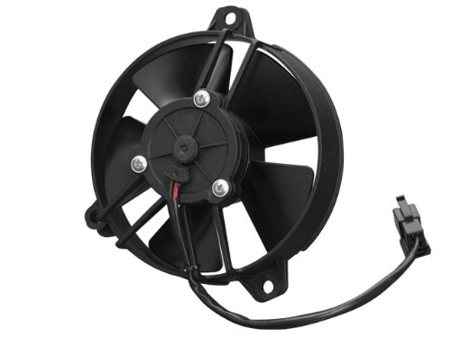
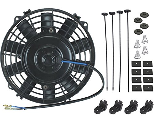
I think adding a powered fan to the oil/fluid cooler would help noticeably
fan5in.jpg


5 inch
http://www.amazon.com/Spal-30103013...eASIN=B009OBP182&ascsubtag=Fan000Oil000Cooler

fan7in.jpg

7 inch
http://www.amazon.com/American-Volt...eASIN=B00SE2RFZ4&ascsubtag=Fan000Oil000Cooler

I think that you need not make the instal complicated just hook it to a switch and relay , mount it to suck through the heat exchange radiator
 
Last edited:
Yes it is custom and built by a good friend Bob (busterrm). I think it 1/4 inch SS
and still need more polishing. In fact he built the trans mount and loop, then he
came to OKC and welded it for me. Can't get much better than that !!!!!!!!!!!!!!
 
.
2nd Rebuild Of This Transmission Starts Here

This is the 2nd rebuild of this trans because of an engine problem that caused me to boil the
fluid. I'm going to pickup the saga here instead of continuing in my TBucket thread.

FP01_IntermediateServo_00598.jpg

FP01_Accumulators_00591.jpg

FP01_Governor_00607.jpg

FP01_ValveBody_00590.jpg

FP01_VavleBodyWormCasting_00594.jpg

The pump internals is where I found the first problem associated with boiling the fluid. The rotor
guide (213) was overheated and became brittle , you can see it started flaking pieces off in the
photo below.

When you see number inside a ( ), then that is the ASTG ID number in their manual.

FP01_RotorGuide(213)_00600.jpg

FP01_RotorGuide(213)_00606.jpg

The surfaces inside the pump where the rotor and rings ride still look good and smooth.

FP01_PumpAssembly_00611.jpg

When you see a number inside a ( ), then that is the ASTG ID number in their technical manual.

 
those are damn good quality pictures and yes Im quite, impressed with your diagnostic skills so far
 
Next inline behind the pump is the Over Run Clutch shown below.

FP01_OverRunClutch(510)_00613.jpg

Then JOHN HANCOCK made the mistake of pulling an snap ring that let the planetary gears out
of their orbit, OK so maybe I helped a little. Therefore I put him in charge of getting them
back in their ORBITS !!! ..... I went for another piss and a new beer !

I was surprised, he used my ASSembly Goo, and they were back where they should be, all happy
next to their SUN !!!

FP01_JohnTheExpert_00620.jpg

THANKS JOHN for your help and support !!!

.
 
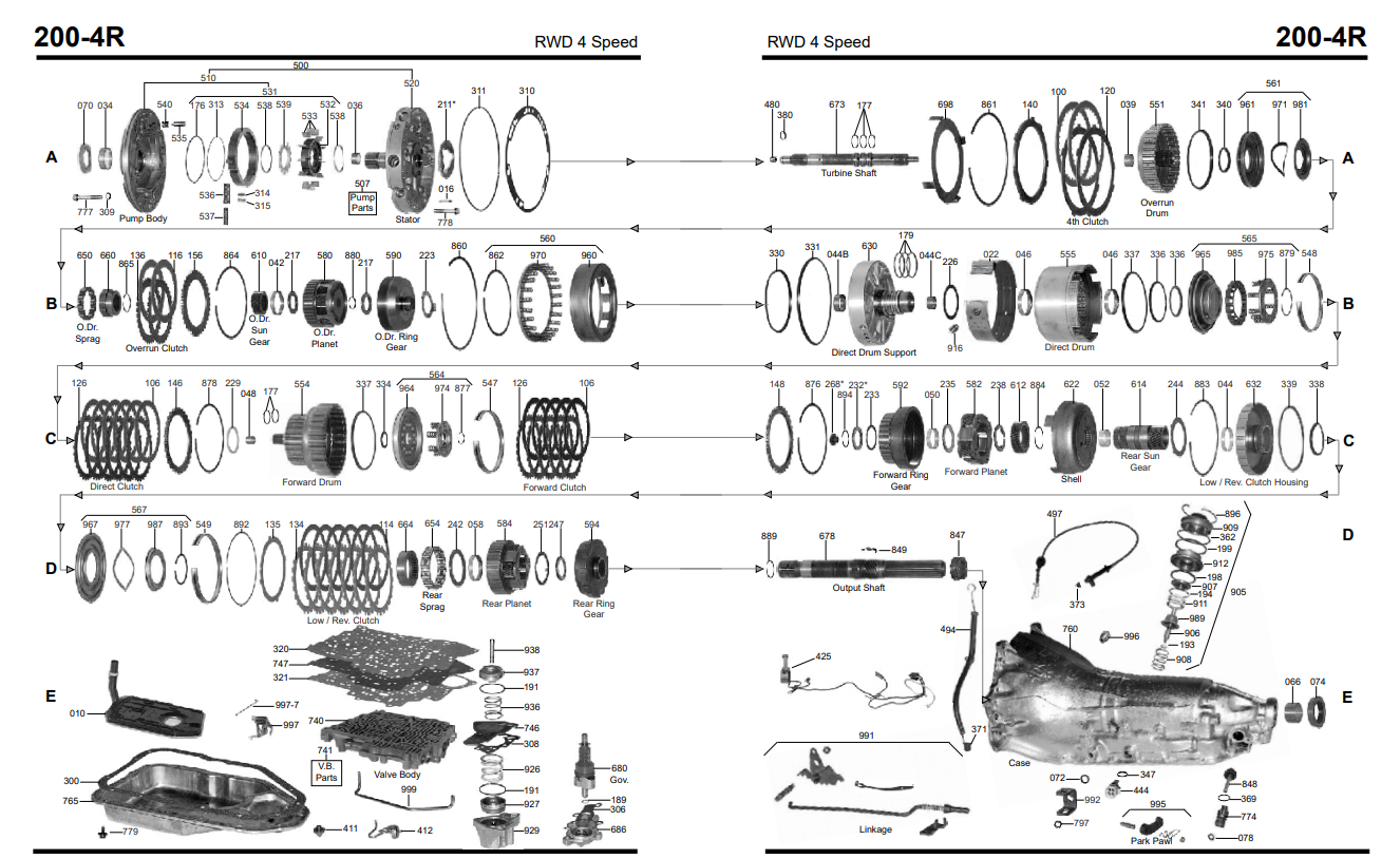
For your reference the ATSG drawings .....

OverDriveComponents.jpg

Working my way thru the trans from front to back. Next would be the Over Run Clutch and Over Drive Clutch.

FP02_OverRunClutchAssembly_00616.jpg
FP02_OverDriveCarrierAssembly_00617.jpg
FP02_OverDriveCarrierAssembly_00618.jpg
FP02_OverRunClutchPiston_00622.jpg

Found my first problem with the retainer of the roller clutch. Doesn't seem to be bad enought to be causing no Reverse
gear, but there is more to come.

FP02_OverRunRollerClutch_00625.jpg
 
your amazing high quality clear photos are very instructive,
thank you and please keep posting more details,
as you continue too progress in your inspection and repairs.
a detailed , step by step, picture description of the repairs would be great!

fb_img_1532610342781_f461a55b0a60b6862f750b1285828b1d1d510bba.jpg


2000r4.png

200-4R.pdf

200-4R.pdf
 
Last edited:
Now, that's a great exploded view using photos instead of the using line drawing. Now if you could
just convert all those numbers to the standard ASTG numbering standard! :)
 
What the pic doesn't show is all the needle bearings on the table. I pulled the wrong snap ring
and didn't realize that the planetary gears were falling out. John came to the rescue and put the
planetary gears back in their orbit!
 
its very impressive that you have proven your able too pull that transmission apart and re-assemble it,
and actually have it function correctly, that puts you guys in a very select and rather unique more advanced group,
than the vast majority of performance car enthusiasts. I feel very comfortable with most engine builds,
and a few muncie 4 speeds have actually functioned after I re-assembled them with new replaced components,
but I have to admit I'm still rather reluctant too build a 4l80E and convert it to full manual control.
so I will dive into that once I get the finances but I'm still researching the tools and procedures..
you can,t learn new skills without getting in over your head at times... but it helps to do extensive research first.:rolleyes::D

http://garage.grumpysperformance.co...ience-converting-a-4l80e-to-full-manual.5579/

http://garage.grumpysperformance.com/index.php?threads/4l80e.11645/#post-54648
 
Grumpy, I know how you feel about not wanting to go in an automatic trans. Working with Rick has given me the courage to jump in with both feet and do my own. His attention to details gives me confidence.
 
Since we are on a new webpage, I'm including the ATSG diagram again.

OverDriveComponents.jpg

Below you see some of the components inside the Over Run clutch.

FP03_OverRunClutchAssembly_00624.jpg

Remove a few more pieces and you see the Over Run clutch piston. Be sure to note the direction
of ALL the lips seals as you disassemble the trans, it will be important. I have decided to also leave
them installed for reference until I come back to replace the seals in the future.

FP03_OverRunClutchPistonSeals(512)_00623.jpg

Next to disassemble will be the 4th gear spring retainer (533) and the 4th gear piston (534). Also
shown is the Thrust Bearing (528). The Over Drive Internal Gear (529) is situated inside (533).

FP03_4thGearClutch_00629.jpg

On the other side of (529) is another Thrust Bearing (531). Your transmission will have a thrust
washer instead, unless it's been modified. The Thrust Bearing takes the thrust between (529) and
the Center Support (537). The Center Support is coming up next.

FP03_OverRunInternalGear(529)_00626.jpg

Also noted below is the Thrust Bearing (531) location on the Center Support.

FP03_CenterSupport(537)_00630.jpg

Again taking note of the lip seal direction.

FP03_CenterSupport(537)_00632.jpg

The Thrust Bearing (541) is another modification to this trans, yours will have a Thrust Washer.

For any of the modifications mentioned here, they are spelled out in great detail
in the first rebuild. Go back to page 1 and start reading.


FP03_CenterSupport(537)_00631.jpg
 
Back
Top