TBucket Engine Project (Dart SHP)

http://www.brodix.com/heads/ik.php

http://www.edelbrock.com/automotive_new ... -210.shtml

http://www.summitracing.com/parts/EDL-5087/

http://www.jegs.com/p/Brodix/Brodix-IK1 ... 9/10002/-1

http://www.profilerperformance.com/sbc-heads-176.html

http://www.trickflow.com/partdetail.asp ... toview=sku

http://www.summitracing.com/parts/TFS-32400006/

viewtopic.php?f=52&t=3543

http://www.airflowresearch.com/index.php?cPath=24_33

http://www.summitracing.com/parts/AFR-1050/

http://www.jegs.com/i/Dart/301/10971143/10002/-1

keep in mind your looking for a combo that maximized mid and upper rpm torque , your NOT building a RACING ENGINE so a 195cc-200cc 210cc port head that flows decent numbers will be about correct,if you decide to go with a longer duration cam later to boost your peak power the heads selected might not be ideal but they certainly should not be a huge restriction either as they can easily exceed 500hp you certainly don,t need to spend several thousand dollars, on race heads on a car thats mostly designed for street performance but you should buy a quality head and if you were to select a modest aluminum performance head that flows at least 250cfm at .500 lift your going to have a decent torque monster combo if the correct compression,cam headers and intakes are used in that combo.
selecting decent quality cylinder heads is one of the MOST important factors that potentially limit your cars power,or allow that engine to make exceptional power.
many guys make the mistake of not buying good heads that flow enough to support the desired horsepower levels or rarely they get into buying a far too large, and expensive race type port head and then make the mistake of not using enough, displacement, cam duration,and intake flow and enough compression and gearing to allow the engine to operate in the upper rpm range where that head can function correctly to its full potential and the need the flow it can provide to the combo.

http://www.profilerperformance.com/raci ... -23-degree

http://www.airflowresearch.com/index.php?cPath=24_33

http://www.jegs.com/i/Brodix/158/102100 ... tId=760699
http://www.brodix.com/heads/ik.php
 
DorianL said:
Damn! I wish I had caught this one since the beginning!
You snooze....you lose !!! :cool:


Check out the "Dynamic Compression Ratio Calculator". If you need one.

Look down below my signature. I love it since I can compare 5 different engine combinations side-by-side. Or I can vary Intake Valve Closing on the same camshaft.
 
Yea, I saw that in your sig... that's where I caught on to this project. WTF was my head?!?!?!
 
Below are the tools that I used to measure the block main bores, bearing shells and crankshaft journals sizes. All this was needed to determine the oil clearance. This was kinda of a practice run, to see if I could come up some reasonable numbers for the main bearing clearances (Oil Clearances). I will still be doing a pre-assembly check with plastigage and I also wanted to see how my number would compare with the machine shop.

Equipment List:
Telescopic Gages (Snap Gages) $25
0-1 inch Ball Micrometer $75
2-3 inch Micrometer (Bought Used)
3/8 inch Torque Wrench
1/2 inch Breaker Bar
Plastic Hammer
Sharpie Maker
Eye Loupe ( 8X Power) $8


EquipmentUsed0447.jpg

I do not claim to be an expert at making very accurate measurement, below is just a few of the things I learned while going through the process.

Steps
1- Torque main cap in to place. Being sure to lubricate the threads, bolt head and washer.

2- Place snap gages in bore, but don't hold them in their middle like in this photo. By holding them in the middle you will force them off the TRUE centerline of the bore, making your measurement smaller than actual main bore diameter.


SnapGagesWrong0460.jpg

3- Once the snap gages are in the bore, then rock them back-and-forth using the handle to allow them to center themselves in the main bore. Their own spring pressure will want to force them to the largest diameter, exactly what you want to measure.
Note: In this photo I cannot hold the snap gages properly by the handle and a finger at the lower contact point while taking the picture.


SnapGageRight0463.jpg

4- When you are ready turn the locking wheel to tighten, then push down slowly as you drag the contact points thru the bore pivoting from the bottom contact point. As they pass thru the main bore, the snap gages with retain the smallest bore size.

5- Measure the snap gages with your outside micrometers and record this diameter. Repeat steps 2 thru 5 three more times. I did 2 measurements each at 10 and 2 o'clock, for a total of 4 measurements. As you will see in my Excel graphic, the
GREEN number is the average of these 4 numbers to calculate my clearances. If you need help with reading a Vernier scale, see the information at the end of this article.

SnapGage&Micrometer0464.jpg

6- Now measure the thickness of the both sides of the bearing shell. To do this I used a ball micrometer. The image below shows why it's called a ball micrometer. If you don't have a ball micrometer, I believe they make attachments for your standard flat face micrometer.


BallMicrometer0470.jpg

7- I got lucky and bought this new very nice ball micrometer for $75 (Normally $300). Yes..... that's right it shows 5 decimal places, the last number is for rounding only.


BearingShellMeasure0477.jpg

8- After measuring the main bearing thickness, I numbered them for later reference. It's always nice when you can go back to compare a number at a later time.


MainBearingIdentification0471.jpg

9- I had already measured the main journals on the crankshaft at 4 locations on each journal; I used the average for clearance calculations. See
RED numbers.
For pictures and more details on crankshaft measurements, use the link below:

viewtopic.php?f=69&t=3814&hilit=Dart+shp&start=10

10- I input all the numbers into Excel. Looking at the graphic below, this is how the clearances were derived.

Green Number - Red Number - Blue Number = Oil Clearance

ExcelCalculations01.JPG

I'm not going to completely trust my numbers, if they are within .0005", I would be very happy with my first attempt. I will use plastigage and the machine shop as another check. At least all the numbers are reasonable.


How to Read a Vernier Scale

Amazon Eye Loupe - $7.44
http://www.amazon.com/General-Tools-527 ... 053&sr=8-8

There are many types of eye loupes, but this one is in focus when the larger diameter end is touching the surface you want to view.

This picture was actually taken with the camera looking thru the eye loupe. All the pictures below make this look like it would be very easy to read since it's bigger than it is in reality. I found it made life much easier to read the Vernier with the eye loupe.


VernierScaleEyeLoupe0449.jpg

First read the front the micrometer to get your measurement to the third decimal place or thousands of an inch.


VernierScaleRead0456.jpg

By resting it directly on the Vernier Scale it's automatically in focus, now you need to decide which line is closest to lined up. There will be ONLY ONE LINE that is really close; all the others will be noticeably either too high or too low.


VernierScaleRead0459.jpg

For the final number add them all together. In this case it would be.
2.0 + 0.6 + 0.025 + 0.016 + 0.0004 = 2.6414 inches
 
Last edited:
Ive got to say,thats rather remarkable photography , you rarely see photos that clear or see guys take the effort to detail the info, CONGRATS ?
in fact, the whole threads rather impressive.
just taking the time to research what needs to be done and checking things are assembled correctly goes a long way to making sure your engine will function correctly
as usually your thinking and actually doing whats required with the parts to get them to function correctly, and yes its the cumulative total of the effect your having with dozens of mostly modifications that seem like a waste of effort on an individual basis that when taken together make a noticeable improvement on the end result, and your sure to find guys who have built or at least bolted together a similar list of components who then find themselves scratching there heads wondering why they failed to get the same result or the same level of durability.
I can assure you the efforts worth the time spent, I had a friend "LARRY" back in the 70s who was convinced that simply bolting a list of parts together was all that was required to build a decent engine.....we had similar income and eventually rather similar cars, but I and most of my friends consistently had little trouble building faster cars because we took the time to do some research and actually fit components correctly rather than take them strait from packaging to bolting them together.
 
grumpyvette said:
Ive got to say,thats rather remarkable photography , you rarely see photos that clear or see guys take the effort to detail the info, CONGRATS ?
in fact, the whole threads rather impressive
Thanks!
Lots of light and a tripod will make a world of difference.
I rather enjoy the documentation process, it will help when I need to check something years down the road.
 
Last edited:
jteu2002 said:
realy nice and clear "how to"use the micrometer
and then i am happy whe use mm :lol:
Thanks jteu2002 !
We really should convert to the metric system like they have been saying for years.

It's just too easy working on cars that have only one system, that's why over here we like to use English and Metric
on the same car. It automatically doubles the exercise we get while working on our cars. I have to make twice
as many trips to the toolbox for what I need.
:D
 

Christmas came again !!! Stopped by Carter's Automotive Machine and picked up a bunch of parts. Crower shipped the roller camshaft and lifters and they arrive yesterday too. Can't believe they left that much money on the porch !

I had a hard time coming in from the garage last night, but I knew 4:30 am would come early.

DSC00488_Resized.jpg
DSC00503_Resized.jpg
DSC00504_Resized.jpg
DSC00495_Resized.jpg


Crower 00471 Camshaft, 555/560 inch lift, 236/240 Duration @ 0.050, LSA = 110

DSC00486_Resized.jpg

Polished Stainless Steel Fasteners for Engine Accessories, 170,000 psi

DSC00513_Resized.jpg
 
damn nice, Im sure your going to be pleased with the results.
that crower roller works great with that dual plane intake, if the compression ratios correct and yours is in the ball park, thats almost sure to produce rather impressive mid rpm torque and upper mid range power with those heads ,without sacrificing any appreciable lower rpm responsiveness, provided the headers and exhaust is low restriction and tuned for that intended 3000rpm-6400rpm power band.

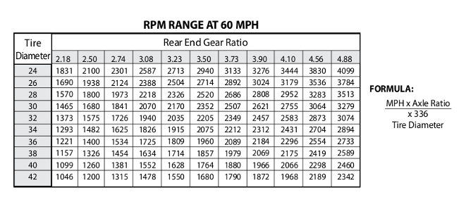
Theres no right or wrong here just preference, as to what your trying to accomplish, yet, I generally install that cam, strait up, not advanced 4 degrees, like most factory cams are set with a dot-to-dot install, now, Id suggest driving the car and getting a feel for the engine first, before making any changes, but if you find you want to move the whole effective power curve up a bit ,having it moved up about 200-rpm,can be accomplished if you can re-index the cam in again strait up, you'll find the current power curve starts and stops about 200-rpm lower than if the cams installed strait up. that may be more responsive but you can add a few peak hp and reduce wheel spin very slightly thru installing the cam strait up.
gearrangec.png

you should ideally select a cam , tire diam. converter stall speed and differential gearing that put the engine rpm range in your power curve about 90% of the time, that CROWER 00471 in a 400 sbc with those brodix 200 cc heads will produce a crisp instantly responsive high torque combo nearly ideal for use with that 200r4 auto transmission, provided you select about a 2800 rpm-3000 rpm stall converter and a shift kit that allows the transmission to shift up near 6300 rpm under full power launches
I think you'll be very pleased with the results as that combo of the crower 00471 and the 200cc brodix heads and the edelbrock dual plane intake has previously produced impressive results.

you might want to read thru these links also

viewtopic.php?f=71&t=741&p=1048#p1048

viewtopic.php?f=55&t=58

viewtopic.php?f=55&t=211

viewtopic.php?f=55&t=8485

http://garage.grumpysperformance.co...gine-to-match-the-cam-specs.11764/#post-55651

http://garage.grumpysperformance.co...octane-for-compression-ratio.2718/#post-50343
 
Last edited by a moderator:
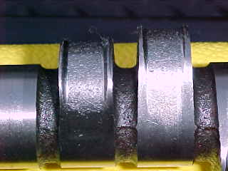
I've never read anything on preparing the camshaft by deburring the edges. The edges are very sharp and would seem to benefit from a couple of passes with a fine file to remove any material that would break loose later while the engine is running.

DSC00483_Commented.jpg
 
Last edited:
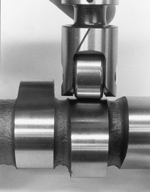
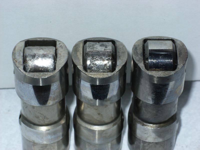
if properly installed the rollers ride in the center area, of the lobe so the edge has zero effect, but I will point out that soft cast cam cores and high roller spring load rates don,t work well in the long run so always spring for the billet cam cores

754c8.jpg


obviously valve train CLEARANCES,
GEOMETRY AND VALVE SPRING LOAD RATES,
AND LUBRICATION FLOW RATES
need to be correct,
and getting into valve loft or valve float rpm levels does BAD THINGS to roller lifters and cam lobes
camlobe2.jpg


082.jpg


ringsealw2.jpg

ringslack.jpg

if the valve train clearances and rings are installed correctly ,cylinder pressure helps ring seal and break-in so don,t be afraid to keep the engine constantly changing rpm and load as this seats both the rings to cylinder walls and throws extra oil mist on the cam lobes, lifters and cylinder walls and maintain enough oil pressure to keep the rockers properly lubricated, adding an oil cooler to the engine has the benefit of keeping the oil temps in the 180F-220F range where , the oil cools and lubes the moving components most effectively

viewtopic.php?f=52&t=181

viewtopic.php?f=52&t=1716&p=4250&hilit=beehive#p4250
 
I would think, if oil flowing over the block surface dislodge particles, then the stresses imposed on the camshaft during operation could have the same effect. Also, it seems there would be a lot less chance of scuffing the cam bearings during installation if the edges were smoother.

Is there a down side to smoothing the edges ???
 
Indycars said:
I would think, if oil flowing over the block surface dislodge particles, then the stresses imposed on the camshaft during operation could have the same effect. Also, it seems there would be a lot less chance of scuffing the cam bearings during installation if the edges were smoother.

Is there a down side to smoothing the edges ???

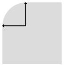
I can,t realistically think of any potential down side to carefully grinding a smooth consistent rounded edge like a 1/32 nd inch radius on those sharp edges, provided you don,t touch the cam lobe or bearing surface,itself, as it might help, the only reason I think its not done is its not critical and it would raise the part cost significantly
radius1.jpg

a 1mm or 1/32" radius on that edge should improve the design and lower the chance of stress rizers
 
Upon closer inspection as you can see in the photo below, there is a edge left from the machining of the cam lobes. It's very easy to catch your finger nail on the edges and looks to me like a potential for metal coming off under the stresses of operation. I used the small file with tape, so that I had only one edge that would do any cutting. Took me about 1 1/2 hours to clean-up both sides of every lobe.

MushroomedEdges0526.jpg
FileWithTape0530.jpg
 
Last edited:
Droool...

Did you already mention the type of head gasket you are using there?
 
Back
Top