TBucket Suspension

8

87vette81big

Guest
Re: TBucket 200-4R Transmission Project

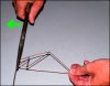
Maybe You & Busterm can add a few strategic placed gussets to the T-bucket frame Rick.
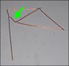
Tri Angle gusset braces.
Bob is an awesome metal fabricator & welder.
Could even be partial bolt in.
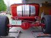
The T- bucket has a Ladder style frame.
Typical of GM musclecar era A body frames.
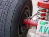
Strength against torsional engine torque wrapup comes from strategic placed crossmembers at front framehorns. And right before frame bends around rear axle housing tubes.
Major torque absoarbtion areas.
1/8 Inch wall ladder frame construction not the weak link in my opinion.
3/16" wall would only be margainally better.
Should be able to increase torsional wrapup resistance at least 30-50% with carefull thinking.

BR
 
Re: TBucket 200-4R Transmission Project

I agree! We would have to figure out where the torsional weakness points are and strengthen them.
I also mirror the comment on the difference in the frame tubing, your not going to gain that much strength using heavier tubing by 1/16. Bracing in the weak points in the frame is the better idea.
 
Re: TBucket 200-4R Transmission Project

FRMW.jpg

FRMW1.jpg

it looks like a section of 2" x 4" box steel between A & B ,needs to be welded in to increase torsional resistance, a plate welded or bolted in place over and onto the area C-D , boxing that area in, and a bolt in brace between E-and F might significantly increase frame rigidity, obviously careful measuring for clearance issues would be required.
now adding a roll cage loop up over the rear of the seats and a rear brace angling back to the new a-b cross brace would not hurt rigidity either, but it would make the car look different and might be a P.I.T.A.
 
Re: TBucket 200-4R Transmission Project


Certainly some good food for thought there guys!

My plan is to drive it for a few weeks to see what shakes out and then over the
winter make some changes.

It would be fun if it's not too complicated to do something like in this article.

http://www.autospeed.com/cms/A_112924/article.html


Attachments

  • StressAnalysis01.jpg
    StressAnalysis01.jpg
    65.7 KB · Views: 69
  • StressAnalysis02.jpg
    StressAnalysis02.jpg
    56 KB · Views: 69
Re: TBucket 200-4R Transmission Project

Rick, if you can get some more pics of the rear frame sections.
Under car shots. Just kneel down and snap pics.
Also I see an old school ladder bar.
Front ladder bar attachment points of intrest to me
All anti squat characteristics happen right there along with vehicle center of gravity makes you hook up hard & fast.
When 100 to 140 % anti squat takes place, the T bucket azz end will actually rise an inch or 2 After hookung up hard on launch.
Drivers side air bag only inside of coil spring likely help hookup too.

Old Pontiac GTO A body & Chevelle trick.

Since we are getting off the subject of the 200-4R transmission, I wanted
to start a different thread.

Here are the pics that 87vette81big requested.


The front mounting points being too long have been brought to my attention
by Grumpy earlier, so that's one change that I would like to make.


Attachments

  • FP01_RearSuspennsion01_0003.jpg
    FP01_RearSuspennsion01_0003.jpg
    56.3 KB · Views: 69
  • FP01_RearSuspennsion02_0034.jpg
    FP01_RearSuspennsion02_0034.jpg
    41.7 KB · Views: 69
  • FP01_RearSuspennsion03_0005.jpg
    FP01_RearSuspennsion03_0005.jpg
    44.4 KB · Views: 69
  • FP01_RearSuspennsion04_0009.jpg
    FP01_RearSuspennsion04_0009.jpg
    53.3 KB · Views: 69
Wish to recap Rick .
I know the T-bucket is a fair weather crusing machine.
Grumpy is excited. He wants you to make a few 1/4 mile passes.
I do too.
ET not so important always. MPH Trap speed at end of 1/4 mile dictates potential if a perfect run was made later on. Such as 125-130mph.
Potential 10's.

The T-bucket looks like it was made in 1960's-70's.

Rear suspension has weak points.
No radius rod ends or heim joints or Aurora rod ends.
Marginal ideal safe with todays engines built as you have.
Danger area is flattened tubing attached to rear housing brackets.
Potential nodule shear point racing hard.
Like that other Supercharged BBC T bucket owner in New Zealand shown yesterday.
Modern 4-link kit like my Competition Engineering 4-link kit was $400 delivered to me from Summit Racing.
Bob can install with you .

Keep other suspension parts for now

Or just use as is..
 
Re: TBucket 200-4R Transmission Project

grumpyvette said:
FRMW.jpg

FRMW1.jpg

it looks like a section of 2" x 4" box steel between A & B ,needs to be welded in to increase torsional resistance, a plate welded or bolted in place over and onto the area C-D , boxing that area in, and a bolt in brace between E-and F might significantly increase frame rigidity, obviously careful measuring for clearance issues would be required.
now adding a roll cage loop up over the rear of the seats and a rear brace angling back to the new a-b cross brace would not hurt rigidity either, but it would make the car look different and might be a P.I.T.A.
I agree with the A&B, and E&F, but I think there is enough structural bracing around the tranny mount to be sufficient.

a 1/4" thick aluminum plate with carefully fitted and welded sections of 1.5: angle aluminum along the edge, as wide as the frame , allowing a couple horizontal bolts into the cross member that had lets say 4 vertical bolts equally spaced along each edge, like on the plates frame edge thru the frame on each side would significantly add to the frames rigidity under twisting or torsional loads

FRMW2.jpg


THERES STUFF IN THIS THREAD AND SUB LINKS THAT MIGHT BE HELPFUL


viewtopic.php?f=46&t=373&p=455#p455

viewtopic.php?f=71&t=1282&p=27698&hilit=dana+60#p27698

viewtopic.php?f=71&t=1755&p=4427#p4427
 
They make mild steel tubing 4-link kits also Rick.
1/2cost of my CCE Pro Magnum 4-link kit.
Kool thing it comes with full installation directions.
Download PDF file from Summits website.
 
At work still Rick.
Difficult to post off my phone.
Be home in a few hours. Put up links for you.
 
87vette81big said:
The T-bucket looks like it was made in 1960's-70's.

Danger area is flattened tubing attached to rear housing brackets.

Potential nodule shear point racing hard.

Damn good guess, it was originally finished in 1980. The same year I graduated from
Oklahoma State University with a 4 year degree in Mechanical Power Technology
and went to Houston to work.

If I remember right from 1980 we stuck the flat bar about an one inch inside the
tube and then welded around the edge. I'm sure we did this to save money, but
it's time for an update.

What is a "nodule shear point ???

 
busterrm said:
a 1/4" thick aluminum plate with carefully fitted and welded sections of 1.5: angle aluminum along the edge, as wide as the frame , allowing a couple horizontal bolts into the cross member that had lets say 4 vertical bolts equally spaced along each edge, like on the plates frame edge thru the frame on each side would significantly add to the frames rigidity under twisting or torsional loads

If not in the area of C-D, then where are you talking about putting this bracing?

 
Nodule Shear Point is Brian talk for if its going to break anywhere Rick, it will be right there at flattened ladder bar tubing attached to welded on rear housing brackets.
Can't self align much at all if any under high driveline torque loads applied.
Unlike an Aurora rod bearing end made out of Chrome Moly steel & hardened bearing steel.

I like bracing between Points A & B.
Frames often crack in these areas in high torque & Hp. cars.
1968-81 C3 Corvette had an excellent perimeter ladder frame. Maybe Grumpy can post engineering prints of it.
5 cross members total from my memory.
 
Indycars said:
busterrm said:
a 1/4" thick aluminum plate with carefully fitted and welded sections of 1.5: angle aluminum along the edge, as wide as the frame , allowing a couple horizontal bolts into the cross member that had lets say 4 vertical bolts equally spaced along each edge, like on the plates frame edge thru the frame on each side would significantly add to the frames rigidity under twisting or torsional loads

If not in the area of C-D, then where are you talking about putting this bracing?

Rick I think Grumpy posted that about the 1/4 inch aluminum plating. My part is the agree with the A and B, E and F areas needing bracing.
 
Back
Top