A few charts and a bit of math go a LONG WAY towards answering a few basic questions, and I'm frequently asked why a certain combination once its built does not live up to the car owners expectations.
I've constantly seen trends over the years and while I'm all too aware most of us build on a very limited budget and because that restricts access to all the components we would like to have in our builds it makes the process far longer and more difficult, yet I also see a STRONG tendency for guys to select components based more on price than part compatibility to the intended goal. in fact at times I get the distinct impression that the parts being bolted together , were almost a random selection of components with the only requirement in their selection being the physical ability too have the parts bolt together.
the fact is that a well planed selection of matched quality components will almost always perform far more effectively that the random mix of bargain priced parts many cars are built from.
a simple choice made while planing the engine, like selecting a bit less duration on a tighter LSA in a cam, or actually accurately measuring the valve train clearances and valve spring load rates can and does make a huge difference in the finished engines durability and power curve!
Id also point out that your vehicles drive train, rear gear, transmission gearing and tire diameter can have a very pronounced effect on how your engine will function
EXAMPLE one of the local guys has a son that started out in this hobby like most of us do, buy buying some ones half finished project car and a wide assortment of parts from friends cast offs and the idea that simply bolting them together , with the help of several enthusiastic but usually equally in-experienced friends,would some how result in a fast car.
YEAH! I'll freely admit I went through a sharp learning curve due to starting out on a similar manor but unlike many guys I've always had a strong tendency to step back and say to myself "WELL CRAP! THAT DIDN,T WORK WORTH A SHIT!" when I screw something up royally, but unlike many or most guys I want to know EXACTLY WHY IT DID NOT WORK!, AND WHAT I COULD DO TO MAKE THE CAR MORE DURABLE, FASTER, OR LESS EXPENSIVE OR EASIER TO WORK ON, OR WHAT TOOL CAN I USE TO DO THAT WITH A GREAT DEAL LESS EFFORT.
theres been hundreds of times where I read through some magazine article, explaining how too do some modification,and think, this guy forgot to mention you can,t do that... without doing ..#$%^&*, or that this guys SKIPPING OVER THE FACT THAT, if you did some other minor modification, the first modification would be far more efficient or more durable.
one of the local guys built a older 1968 camaro with a low compression 454 big block, engine he pulled from a donor motor home, he installed a rather aggressive roller cam in place of the original STOCK roller cam with no thought to the non-adjustable valve train, and the woefully inadequate valve spring load rates and clearances. that engine was also severely compromised, because the original 307 sbc exhaust system in the car, was designed for a small block engine that would have strangled the engines performance once the engine rpms went much past about 4000 rpm.
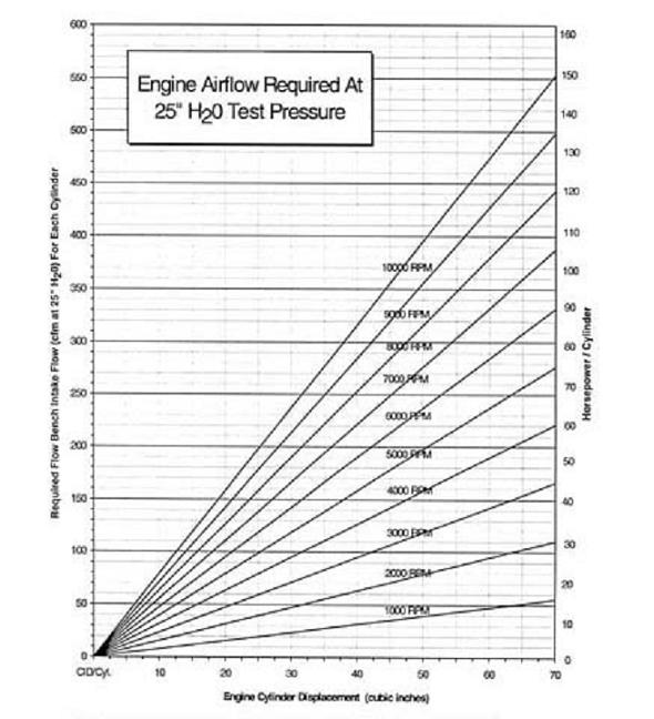
look at the chart below
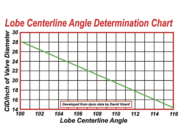
now assume your BBC has 2.06 diameter intake valves, and displaces 454 cubic inches ,like this example did, a 454 big block chevy, thats 56.75 cubic inches per cylinder divided by 2.06 equals 27.55
looking at the chart it should be rather obvious that a much tighter LSA than the 114 LSA that was selected in this case, would have potentially enhanced the engines ability to efficiently fill the cylinders and the very restrictive exhaust was obviously used to save money but would be a very obvious and measurable problem area restricting the engines power potential.
Potential HP based on Airflow (Hot Rod, Jun '99, p74):
Airflow at 28" of water x 0.257 x number of cylinders = potential HP
or required airflow based on HP:
HP / 0.257 / cylinders = required airflow
USE THE CALCULATORS, YOULL, QUICKLY FIND THE LIMITATIONS
http://www.rbracing-rsr.com/runnertorquecalc.html
http://www.wallaceracing.com/chokepoint.php
http://www.wallaceracing.com/header_length.php
related info, that you might need
http://garage.grumpysperformance.co...heads-for-small-block-chevys.3293/#post-26213
http://garage.grumpysperformance.com/index.php?threads/what-are-these-heads.4702/#post-12742
http://garage.grumpysperformance.co...-by-step-guide-with-pictures.5378/#post-71848
http://garage.grumpysperformance.co...ther-efi-intake-manifold-info.431/#post-26322
http://garage.grumpysperformance.com/index.php?threads/porting-can-help.462/page-3#post-59145
http://garage.grumpysperformance.co...ads-tuned-intake-turbulence.12998/#post-67611
Volume (CCs) of Head Gasket
CCs of Head Gasket = Bore x Bore x 12.87 x Thickness of Head Gasket
COMMON SBC INTAKE PORTS
felpro # 1204=Port Size: 1.23" x 1.99"=2.448 sq inches
felpro # 1205=Port Size: 1.28" x 2.09"=2.67 sq inches
felpro # 1206=Port Size: 1.34" x 2.21"=2.96 sq inches
felpro # 1207=Port Size: 1.38" x 2.28"=3.146 sq inches
felpro # 1209=Port Size: 1.38" x 2.38"=3.28 sq inches
felpro # 1255 VORTEC=Port Size: 1.08" x 2.16"-2.33 sq inches
felpro # 1263=Port Size: 1.31" x 2.02"=2.65 sq inches
felpro # 1266=Port Size: 1.34" x 2.21"=2.96 sq inches
felpro # 1284 LT1=Port Size: 1.25 x 2.04''=2.55 sq inches
felpro # 1289 FASTBURN=Port Size: 1.30" x 2.31" 3.00 sq inches
http://users.erols.com/srweiss/calccsa.htm
Your RPM computed from your Cross Sectional Area of 1.95
(the smaller AFR HEADS)
and Bore of 4.03 and Stroke of 3.75 is 5,569.12 .
Your RPM computed from your Cross Sectional Area of 2.05
(the Larger AFR HEADS)
and Bore of 4.03 and Stroke of 3.75 is 5,854.72 .
you,ll barely notice the about 300 rpm shift in the power band on the lower part of rpm range but appreciate it much more on the upper edge of that power curve
heres a chart FROM THE BOOK,HOW TO BUILD BIG-INCH CHEVY SMALL BLOCKS with some common cross sectional port sizes
(measured at the smallest part of the ports)
...........................sq inches........port cc
edelbrock performer rpm ....1.43.............170
vortec......................1.66.............170
tfs195......................1.93.............195
afr 180.....................1.93.............180
afr 195.....................1.98.............195
afr 210.....................2.05.............210
dart pro 200................2.06.............200
dart pro 215................2.14.............215
brodix track 1 .............2.30.............221
dart pro 1 230..............2.40.............230
edelbrock 23 high port .....2.53.............238
edelbrock 18 deg............2.71.............266
tfs 18 deg..................2.80.............250
USE THE CALCULATORS
http://www.rbracing-rsr.com/runnertorquecalc.html
http://www.wallaceracing.com/chokepoint.php
http://www.wallaceracing.com/header_length.php
http://www.superchevy.com/how-to/en...-0902-chevy-engine-port-variations-measuring/
http://www.hotrod.com/articles/choosing-the-right-camshaft/
http://garage.grumpysperformance.com/index.php?threads/bits-of-383-info.38/
Last edited: 1 minute ago
related threads
viewtopic.php?f=52&t=10705
viewtopic.php?f=52&t=333
viewtopic.php?f=52&t=1070
viewtopic.php?f=52&t=181
viewtopic.php?f=71&t=741
http://www.maliburacing.com/patrick_budd_article.htm
viewtopic.php?f=56&t=495
viewtopic.php?f=56&t=1166
viewtopic.php?f=56&t=3155
viewtopic.php?f=71&t=555
viewtopic.php?f=52&t=8460
viewtopic.php?f=52&t=3802
viewtopic.php?f=52&t=480
I've constantly seen trends over the years and while I'm all too aware most of us build on a very limited budget and because that restricts access to all the components we would like to have in our builds it makes the process far longer and more difficult, yet I also see a STRONG tendency for guys to select components based more on price than part compatibility to the intended goal. in fact at times I get the distinct impression that the parts being bolted together , were almost a random selection of components with the only requirement in their selection being the physical ability too have the parts bolt together.
the fact is that a well planed selection of matched quality components will almost always perform far more effectively that the random mix of bargain priced parts many cars are built from.
a simple choice made while planing the engine, like selecting a bit less duration on a tighter LSA in a cam, or actually accurately measuring the valve train clearances and valve spring load rates can and does make a huge difference in the finished engines durability and power curve!
Id also point out that your vehicles drive train, rear gear, transmission gearing and tire diameter can have a very pronounced effect on how your engine will function
EXAMPLE one of the local guys has a son that started out in this hobby like most of us do, buy buying some ones half finished project car and a wide assortment of parts from friends cast offs and the idea that simply bolting them together , with the help of several enthusiastic but usually equally in-experienced friends,would some how result in a fast car.
YEAH! I'll freely admit I went through a sharp learning curve due to starting out on a similar manor but unlike many guys I've always had a strong tendency to step back and say to myself "WELL CRAP! THAT DIDN,T WORK WORTH A SHIT!" when I screw something up royally, but unlike many or most guys I want to know EXACTLY WHY IT DID NOT WORK!, AND WHAT I COULD DO TO MAKE THE CAR MORE DURABLE, FASTER, OR LESS EXPENSIVE OR EASIER TO WORK ON, OR WHAT TOOL CAN I USE TO DO THAT WITH A GREAT DEAL LESS EFFORT.
theres been hundreds of times where I read through some magazine article, explaining how too do some modification,and think, this guy forgot to mention you can,t do that... without doing ..#$%^&*, or that this guys SKIPPING OVER THE FACT THAT, if you did some other minor modification, the first modification would be far more efficient or more durable.
one of the local guys built a older 1968 camaro with a low compression 454 big block, engine he pulled from a donor motor home, he installed a rather aggressive roller cam in place of the original STOCK roller cam with no thought to the non-adjustable valve train, and the woefully inadequate valve spring load rates and clearances. that engine was also severely compromised, because the original 307 sbc exhaust system in the car, was designed for a small block engine that would have strangled the engines performance once the engine rpms went much past about 4000 rpm.
look at the chart below
now assume your BBC has 2.06 diameter intake valves, and displaces 454 cubic inches ,like this example did, a 454 big block chevy, thats 56.75 cubic inches per cylinder divided by 2.06 equals 27.55
looking at the chart it should be rather obvious that a much tighter LSA than the 114 LSA that was selected in this case, would have potentially enhanced the engines ability to efficiently fill the cylinders and the very restrictive exhaust was obviously used to save money but would be a very obvious and measurable problem area restricting the engines power potential.
Potential HP based on Airflow (Hot Rod, Jun '99, p74):
Airflow at 28" of water x 0.257 x number of cylinders = potential HP
or required airflow based on HP:
HP / 0.257 / cylinders = required airflow
USE THE CALCULATORS, YOULL, QUICKLY FIND THE LIMITATIONS
http://www.rbracing-rsr.com/runnertorquecalc.html
http://www.wallaceracing.com/chokepoint.php
http://www.wallaceracing.com/header_length.php
related info, that you might need
http://garage.grumpysperformance.co...heads-for-small-block-chevys.3293/#post-26213
http://garage.grumpysperformance.com/index.php?threads/what-are-these-heads.4702/#post-12742
http://garage.grumpysperformance.co...-by-step-guide-with-pictures.5378/#post-71848
http://garage.grumpysperformance.co...ther-efi-intake-manifold-info.431/#post-26322
http://garage.grumpysperformance.com/index.php?threads/porting-can-help.462/page-3#post-59145
http://garage.grumpysperformance.co...ads-tuned-intake-turbulence.12998/#post-67611
Volume (CCs) of Head Gasket
CCs of Head Gasket = Bore x Bore x 12.87 x Thickness of Head Gasket
COMMON SBC INTAKE PORTS
felpro # 1204=Port Size: 1.23" x 1.99"=2.448 sq inches
felpro # 1205=Port Size: 1.28" x 2.09"=2.67 sq inches
felpro # 1206=Port Size: 1.34" x 2.21"=2.96 sq inches
felpro # 1207=Port Size: 1.38" x 2.28"=3.146 sq inches
felpro # 1209=Port Size: 1.38" x 2.38"=3.28 sq inches
felpro # 1255 VORTEC=Port Size: 1.08" x 2.16"-2.33 sq inches
felpro # 1263=Port Size: 1.31" x 2.02"=2.65 sq inches
felpro # 1266=Port Size: 1.34" x 2.21"=2.96 sq inches
felpro # 1284 LT1=Port Size: 1.25 x 2.04''=2.55 sq inches
felpro # 1289 FASTBURN=Port Size: 1.30" x 2.31" 3.00 sq inches
http://users.erols.com/srweiss/calccsa.htm
Your RPM computed from your Cross Sectional Area of 1.95
(the smaller AFR HEADS)
and Bore of 4.03 and Stroke of 3.75 is 5,569.12 .
Your RPM computed from your Cross Sectional Area of 2.05
(the Larger AFR HEADS)
and Bore of 4.03 and Stroke of 3.75 is 5,854.72 .
you,ll barely notice the about 300 rpm shift in the power band on the lower part of rpm range but appreciate it much more on the upper edge of that power curve
heres a chart FROM THE BOOK,HOW TO BUILD BIG-INCH CHEVY SMALL BLOCKS with some common cross sectional port sizes
(measured at the smallest part of the ports)
...........................sq inches........port cc
edelbrock performer rpm ....1.43.............170
vortec......................1.66.............170
tfs195......................1.93.............195
afr 180.....................1.93.............180
afr 195.....................1.98.............195
afr 210.....................2.05.............210
dart pro 200................2.06.............200
dart pro 215................2.14.............215
brodix track 1 .............2.30.............221
dart pro 1 230..............2.40.............230
edelbrock 23 high port .....2.53.............238
edelbrock 18 deg............2.71.............266
tfs 18 deg..................2.80.............250
USE THE CALCULATORS
http://www.rbracing-rsr.com/runnertorquecalc.html
http://www.wallaceracing.com/chokepoint.php
http://www.wallaceracing.com/header_length.php
http://www.superchevy.com/how-to/en...-0902-chevy-engine-port-variations-measuring/
http://www.hotrod.com/articles/choosing-the-right-camshaft/
http://garage.grumpysperformance.com/index.php?threads/bits-of-383-info.38/
Last edited: 1 minute ago
related threads
viewtopic.php?f=52&t=10705
viewtopic.php?f=52&t=333
viewtopic.php?f=52&t=1070
viewtopic.php?f=52&t=181
viewtopic.php?f=71&t=741
http://www.maliburacing.com/patrick_budd_article.htm
viewtopic.php?f=56&t=495
viewtopic.php?f=56&t=1166
viewtopic.php?f=56&t=3155
viewtopic.php?f=71&t=555
viewtopic.php?f=52&t=8460
viewtopic.php?f=52&t=3802
viewtopic.php?f=52&t=480
Last edited by a moderator: