The vacuum line to the air cleaner housing?

chromebumpers

solid fixture here in the forum
Staff member
image.jpg image.jpg image.jpg It's missing the hose, but where does it connect to on the 2 Jet? Does it really benefit the operation of the motor?
 
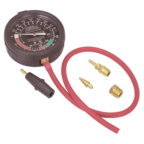
There was a special Vacuum line fitting on the front of the Pontiac intake manifold original .
Its now blocked off by the square head brass Pipe thread plug.
Next to the casted in Engine firing order 1-8-4-3-6-5-7-2 .
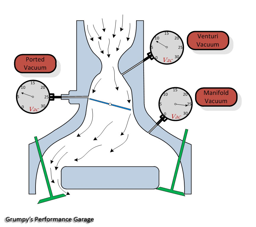
The vacuum line was constant engine manifold Fed.
The air cleaner thermostatic valve remsins closed in cool weather operating conditions.
Fall and winter.
It also prevents carburator icing.
Draws Hot air in through the exhaust manifold tin shield on Drivers side.
Ram Air 4 & 1971-72 455 HO Had dual hot air stoves.
All other engines single Hot Air Stove.
Does make a difference in Fall time driveability with near stock & mild aftermarket cams used.
 
I'm putting on a new 2" tube between the exhaust manifold and the bottom of the air cleaner snorkel but what is that little thing with "AC" molded into it that is inside the filter element area that is vacuum controlled? Isn't that too much vacuum coming directly from the manifold?image.jpg
 
Its a temperture sensing Bi-Metal vacuum switch.
Fully Automatic control.
Needs full intake vacuum at all times.
 
Hey Brian no offense meant but do you read the Pontiac encyclopedia every night damn
 
Its a temperture sensing Bi-Metal vacuum switch.
Fully Automatic control.
Needs full intake vacuum at all times.
Ok thank you, but what is it for? Should I hook this up? I can understand the job of the 2" conduit from the exhaust manifold to the air cleaner snorkel, but why does it need vacuum too?
 
Last edited:
The Vacuum door motor on the air cleaner works off of engine intake manifold vacuum.
 
found this info you might need posted elseware

See Figures 1 and 2

All engines covered in this guide utilize the THERMAC system (in 1978 it was called TAC, but was the same). This system is designed to warm the air entering the carburetor when underhood temperatures are low, and to maintain a controlled air temperature into the carburetor at all times. By allowing preheated air to enter the carburetor, the amount of time the choke is on is reduced, resulting in better fuel economy and lower emissions. Engine warm-up time is also reduced.

heatfil1.gif

The Thermac system is composed of the air cleaner body, a filter, sensor unit, vacuum diaphragm, damper door, and associated hoses and connections. Heat radiating from the exhaust manifold is trapped by a heat stove and is ducted to the air cleaner to supply heated air to the carburetor. A movable door in the air cleaner case snorkel allows air to be drawn in from the heat stove (cold operation) or from underhood air (warm operation). The door position is controlled by the vacuum motor, which receives intake manifold vacuum as modulated by the temperature sensor.
heatfil2.gif


heatfil8.gif

heatfil9.gif

2713s.jpg


VenturiVacuum01.jpg

http://www.harborfreight.com/fuel-pump-and-vacuum-tester-93547.html

http://www.mityvac.com/pages/products_hvp.asp

vacpump1a.jpg


irtemp.jpg

http://www.professionalequipment.com/ex ... ermometer/
Wide temperature range from -58 to 1832°F (-50 to 1000°C)

heatfil10.jpg

heatfil11.png

COMPONENT TESTING


    • Check the vacuum hoses for leaks, kinks, breaks, or improper connections and correct any defects.
    • With the engine off, check the position of the damper door within the snorkel. A mirror can be used to make this job easier. The damper door should be open to admit outside air.
    • Apply at least 7 in. Hg of vacuum to the damper diaphragm unit. The door should close. If it does not, check the diaphragm linkage for binding and correct hookup.
    • With vacuum still applied and the door closed, clamp the tube to trap the vacuum. If the door does not remain closed, there is a leak in the diaphragm assembly.
    • If the diaphragm is holding vacuum and the system has source vacuum, the last choose is the air bleed valve located in the air cleaner assembly.
    • The air bleed may be holding the damper door closed even after the vehicle has warmed up. Or the valve may not close the door at all. In any case, if the damper diaphragm and vacuum source are OK, replace the air bleed valve.

REMOVAL & INSTALLATION

See Figures 3, 4, 5, 6 and 7

Vacuum Motor


    • Remove the air cleaner and the vacuum hose from the motor.
    • Drill out the two spot welds and remove the retaining strap.
    • Lift up motor, cocking it to one side to unhook the motor linkage at the control damper assembly.
    • Install the vacuum motor linkage into the control damper assembly.
    • Use a sheet metal screw to resecure the motor retaining strap.
    • Reinstall the vacuum hose and the air cleaner.
Sensor


    • Remove the air cleaner and vacuum hoses.
    • Pry up the tabs on the sensor retaining clip. Remove the clip and the sensor from the air cleaner. Note the position of sensor for installation.
    • Install the sensor and gasket in original position.
    • Install vacuum hoses and air cleaner.
heatfil3.gif

Fig. 3: Remove the air cleaner cover and element
heatfil4.gif

Fig. 4: On some models, the air intake hose is retained by small lock tabs
heatfil5.gif

Fig. 5: Be sure to label all vacuum hoses when disconnecting them
heatfil6.gif

Fig. 6: To remove any other sensors or switches from the side of the air cleaner, simply pull the retaining clip out
heatfil7.gif

Fig. 7: The Thermac sensor is located on the bottom of the air cleaner. Pry the retaining off to remove the sensor
 
Last edited:
Back
Top