heres some basic info in my hard drive records
http://www.thirskauto.net/Engine_Thrust_Bearings.html
http://www.aera.org/tech/tb1465r.htm
viewtopic.php?f=50&t=9409
http://www.stealth316.com/misc/clevite-77-rod-main-bearings.pdf
http://www.small-block-chevy.com/assemblyspec.html
http://www.4secondsflat.com/Thrust_bear ... lures.html
http://www.circletrack.com/techarticles ... to_04.html
http://www.popularhotrodding.com/tech/0 ... e_control/
http://www.circletrack.com/enginetech/c ... ce_basics/
http://www.enginebuildermag.com/Article ... ilure.aspx
https://www.thomasnet.com/products/crankshaft-repair-services-20921979-1.html
http://members.rennlist.com/v1uhoh/cranksha.htm
http://www.atra-gears.com/crankshaft/
http://www.chevyhiperformance.com/tech/ ... ance_info/
Why Engine Thrust Bearings Fail
Often, soon after an engine rebuild, premature engine thrust bearing failure occurs. We will discuss some of the major causes of these types of failures.
One of the most common causes of thrust bearing failures is the transmission torque convertor. When the overrunning clutch in a torque convertor becomes either seized or will not lock up in one direction, the stator does not provide it's normal function of directing the transmission fluid to create the proper torque multiplication required to drive the vehicle. When this happens, a large amount of the energy created is exhausted through the center of the torque convertor, creating excessive forward pressure. It is this pressure which causes the engine thrust bearing damage. When installing a new engine, it is wise to check the convertor your self, or have a qualified transmission rebuilder inspect it for over running clutch problems.
Improper installation of the torque convertor in the transmission front pump can also lead to bearing failure, as well as transmission failure.
Vehicles with standard transmissions may also experience this type of engine failure due to high clutch pressures, usually related to performance clutches with high spring pressures being installed. Riding the clutch can also cause thrust bearing failure on new engines. You must also ensure the clutch has adequate free play.
Symptoms of damage caused by excessive external pressure on the crankshaft vary on engines due to their design differences.
Small block Chev engines usually suffer catastrophic damage from excessive external pressures. In most cases the thrust bearing show signs of heavy rubbing on the thrust bearing. The most severe damage it on the other mains bearings, with the highest wear being on the center bearing, usually concentrated on the lower half of the bearing. The intermediate main bearings will have about half the wear of the center bearing, with the front and rear bearing showing little sign of problem.
Big block Chev engines, due to the rigidity of their crankshaft, will usually only destroy the thrust face of the thrust bearing, causing little damage to the other mains.
Engines with a center thrust bearing usually, as well as rubbing the thrust surface, will show signs of wear on the opposite sides of the crankshaft on the two intermediate bearings.
I have seen cases of thust bearing failure on small block Ford engines that do not seem have an apparant cause. Upon checking the inner part of the bearing that seats in the block, signs of scraping on the bearing were noticed. This is the result of the installer trying to install the bearing in the rear location instead of the center, where the thrust bearing is located in this type of engine.
Crankshaft Thrust Bearing Failure - Causes & Remedies
For years both transmission and engine rebuilders have struggled at times to determine the cause of crankshaft thrust bearing failures. In most instances, all of the facts concerning the situation are not revealed at the onset of the failure. This has led to each party blaming the other for the failure based only on hearsay or what some "expert" has termed the "cause". Some of those explanations have led to an argument, that ends up in litigation while the truth lingers uncovered in the background. This document is a group effort of combined information compiled by the Automotive Transmission Rebuilders Association (ATRA), the Automotive Engine Rebuilders Association (AERA), the Production Engine Rebuliders Association (PERA), the Automotive Service Association (ASA) and bearing manufacturers. This group of industry experts has assembled the following information to consider and offers solutions that may prevent a similar thrust bearing failure.
Background:
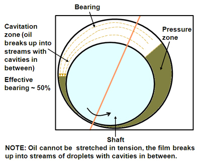
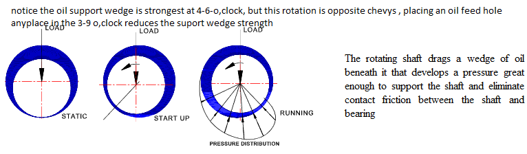
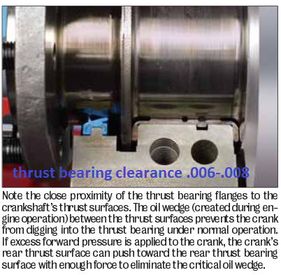
Although thrust bearings run on a thin film of oil, just like radial journal (connecting rod and main) bearings, they cannot support nearly as much load. While radial bearings can carry loads measured in thousands of pounds per square inch of projected bearing area, thrust bearings can only support loads of a few hundred pounds per square inch. Radial journal bearings develop their higher load capacity from the way the curved surfaces of the bearing and journal meet to form a wedge. Shaft rotation pulls oil into this wedge shaped area of the clearance space to create an oil film which actually supports the shaft. Thrust bearings typically consist of two flat mating surfaces with no natural wedge shape in the clearance space to promote the formation of an oil film to support the load.
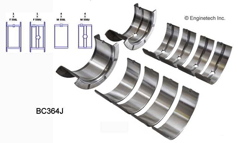
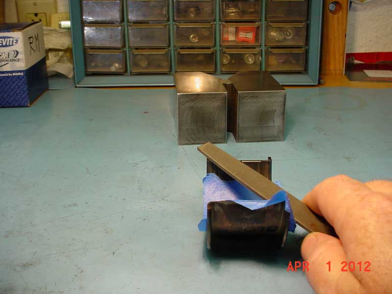
Conventional thrust bearings are made by incorporating flanges, at the ends of a radial journal bearing. This provides ease in assembly and has been used successfully for many years. Either teardrop or through grooves on the flange, face and wedge shaped ramps at each parting line allow oil to enter between the shaft and bearing surfaces. However, the surface of the shaft, as well as the vast majority of bearing surfaces, are flat. This flatness makes it more difficult to create and maintain an oil film. As an example; if two gauge blocks have a thin film of oil on them, and are pressed together with a twisting action, the blocks will stick together. This is similar to what happens when a thrust load is applied to the end of a crankshaft and oil squeezes out from between the shaft and bearing surfaces. If that load is excessive, the oil film collapses and the surfaces want to stick together resulting in a wiping action and bearing failure. For this reason, many heavy-duty diesel engines use separate thrust washers with a contoured face to enable them to support higher thrust loads. These thrust washers either have multiple tapered ramps and relatively small flat pads, or they have curved surfaces that follow a sine-wave contour around their circumference.
Recent developments:
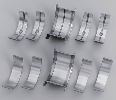
In the past few years some new automotive engine designs include the use of contoured thrust bearings to enable them to carry higher thrust loads imposed by some of the newer automatic transmissions. Because it’s not practical to incorporate contoured faces on one piece flanged thrust bearings, these new engine designs use either separate thrust washers or a flanged bearing which is a three piece assembly.
Cause of failure:
Aside from the obvious causes, such as dirt contamination and misassembly, there are only three common factors which generally cause thrust bearing failures. They are:
Poor crankshaft surface finish
Misalignment
Overloading
Surface finish:
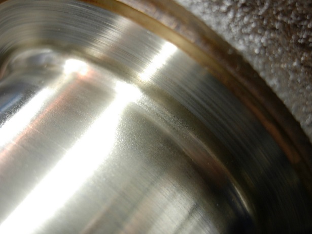
Crankshaft thrust faces are difficult to grind because they are done using the side of the grinding wheel. Grinding marks left on the crankshaft face produce a visual swirl or sunburst pattern with scratches - sometimes crisscrossing - one another in a cross-hatch pattern similar to hone marks on a cylinder wall. If these grinding marks are not completely removed by polishing, they will remove the oil film from the surface of the thrust bearing much like multiple windshield wiper blades. A properly finished crankshaft thrust face should only have very fine polishing marks that go around the thrust surface in a circumferential pattern.
Alignment:
The grinding wheel side face must be dressed periodically to provide a clean, sharp cutting surface. A grinding wheel that does not cut cleanly may create hot spots on the work piece leading to a wavy, out-of-flat surface. The side of the wheel must also be dressed at exactly 90° to its outside diameter, to produce a thrust face that is square to the axis of the main bearing journal. The crankshaft grinding wheel must be fed into the thrust face very slowly and also allowed to "spark out" completely. The machinist should be very careful to only remove minimal stock for a "clean-up" of the crankshaft surface.
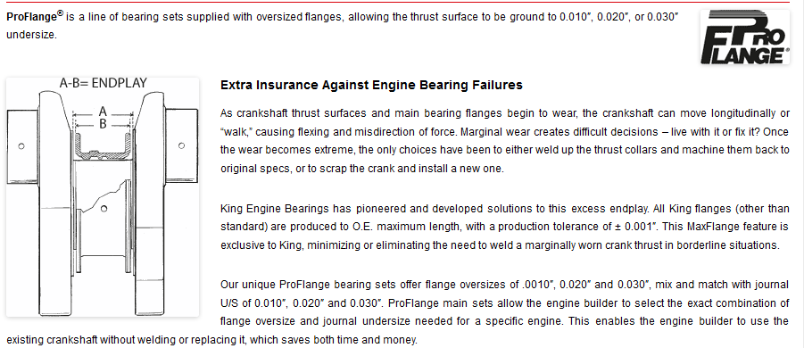
In most instances a remanufactured crankshaft does not require grinding of the thrust face(s), so the grinding wheel will not even contact them. Oversize thrust bearings do exist. Some main bearing sets are supplied only with an additional thickness thrust bearing. In most of those instances, additional stock removal from the crankshaft thrust face surface may be required. Crankshaft end float should be calculated and determined before grinding additional material from the thrust face.
Crankshaft grinding wheels are not specifically designed for use of the wheel side for metal removal. Grinding crankshaft thrust faces requires detailed attention during the procedure and repeated wheel dressings may be required. Maintaining sufficient coolant between the grinding wheel and thrust surface must be attained to prevent stone loading and "burn" spots on the thrust surface. All thrust surface grinding should end in a complete "spark out" before the grinding wheel is moved away from the area being ground. Following the above procedures with care should also maintain a thrust surface that is 90° to the crankshaft centerline.
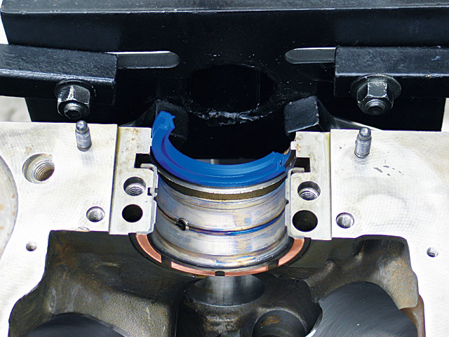
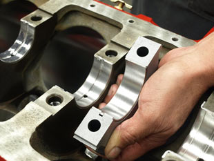
When assembling thrust bearings:
Tighten main cap bolts to approximately 10 to 15 ft.lb. to seat bearings, then loosen.
Tap main cap toward rear of engine with a soft faced hammer.
Tighten main cap bolts, finger tight.
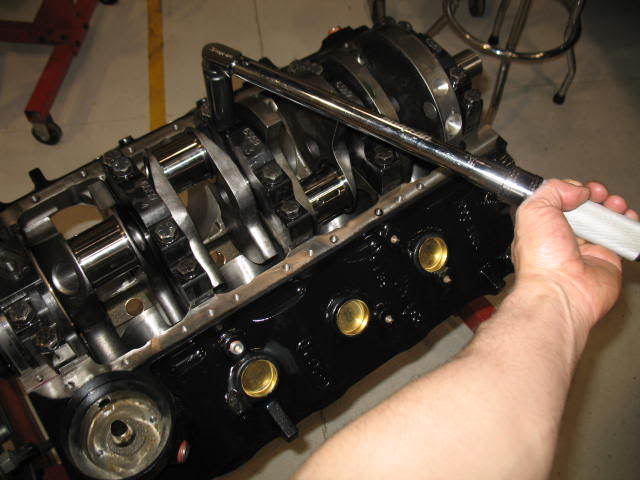
Using a bar, force the crankshaft as far forward in the block as possible to align the bearing rear thrust faces.
While holding shaft in forward position, tighten main cap bolts to 10 to 15 ft.lbs.
Complete tightening main cap bolts to specifications in 2 or 3 equal steps.
The above procedure should align the bearing thrust faces with the crankshaft to maximize the amount of bearing area in contact for load carrying.
Loading:
A number of factors may contribute to wear and overloading of a thrust bearing, such as:
1. Poor crankshaft surface finish.
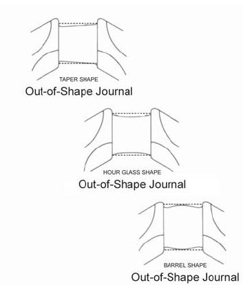
2. Poor crankshaft surface geometry.
3. External overloading due to.
a) Excessive Torque converter pressure.
b) Improper throw out bearing adjustment.
c) Riding the clutch pedal.
d) Excessive rearward crankshaft load pressure due to a malfunctioning front mounted accessory drive.
Note: There are other, commonly-thought issues such as torque converter ballooning, the wrong flexplate bolts, the wrong torque converter, the pump gears being installed backward or the torque converter not installed completely. Although all of these problems will cause undo force on the crankshaft thrust surface, it will also cause the same undo force on the pump gears since all of these problems result in the pump gear pressing on the crankshaft via the torque converter. The result is serious pump damage, in a very short period of time (within minutes or hours).
Diagnosing the problem:
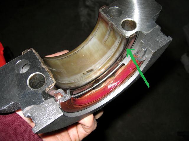
By the time a thrust bearing failure becomes evident, the parts have usually been so severely damaged that there is little if any evidence of the cause. The bearing is generally worn into the steel backing which has severely worn the crankshaft thrust face as well. So how do you tell what happened? Start by looking for the most obvious internal sources.
Engine related problems:
Is there evidence of distress anywhere else in the engine that would indicate a lubrication problem or foreign particle contamination?
Were the correct bearing shells installed, and were they installed correctly?
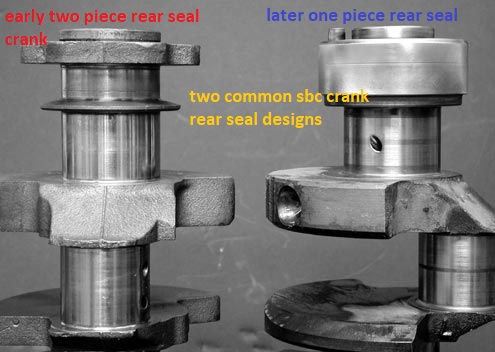
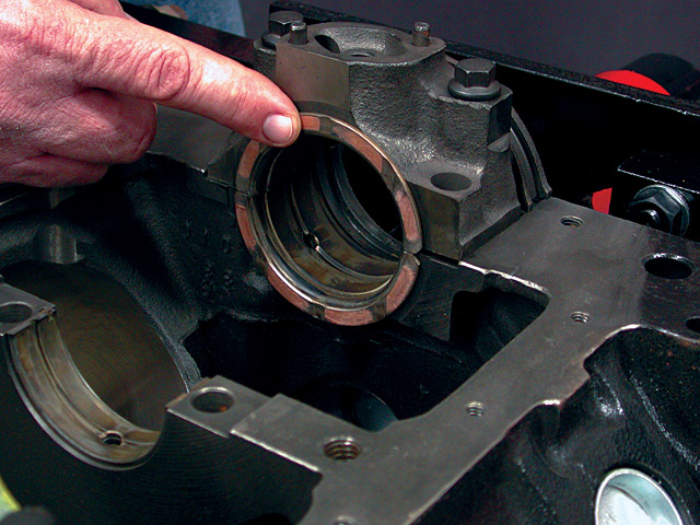
If the thrust bearing is in an end position, was the adjacent oil seal correctly installed? An incorrectly installed rope seal can cause sufficient heat to disrupt bearing lubrication.
Examine the front thrust face on the crankshaft for surface finish and geometry. This may give an indication of the original quality of the failed face.
Once you are satisfied that all potential internal sources have been eliminated, ask about potential external sources of either over loading or misalignment.
Transmission related problems:
Did the engine have a prior thrust bearing failure?
What external parts were replaced?
Were there any performance modifications made to the transmission?
Was an additional cooler for the transmission installed?
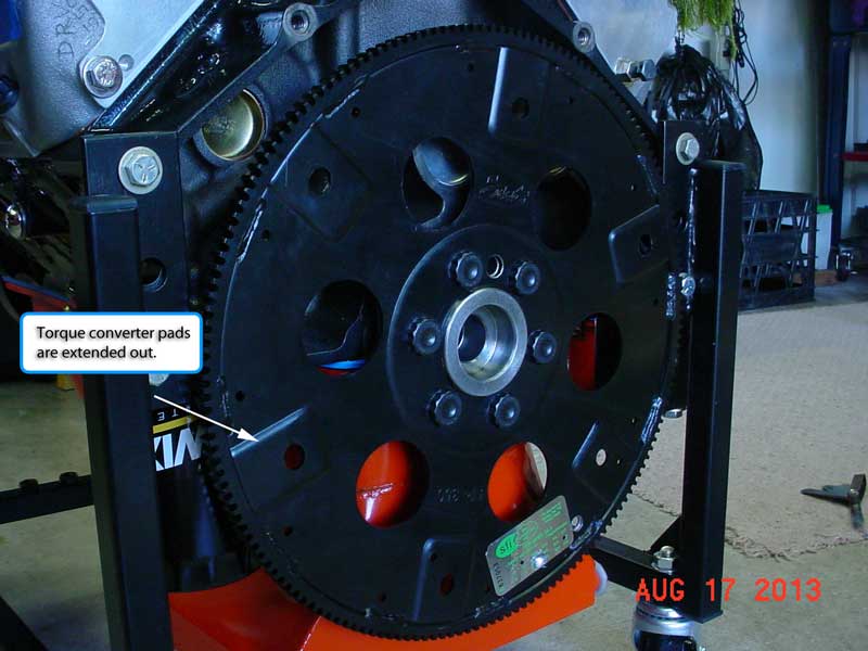
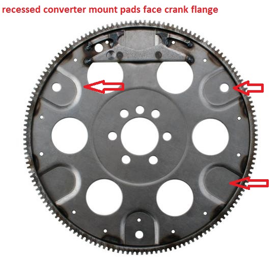
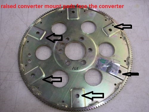
Was the correct flexplate used? At installation there should be a minimum of 1/16" (1/8" preferred, 3/16" maximum) clearance between the flex plate and converter to allow for converter expansion.
Was the transmission property aligned to the engine?
Were all dowel pins in place?
Was the transmission-to-cooler pressure checked and found to be excessive? If the return line has very low pressure compared to the transmission-to-cooler pressure line, check for a restricted cooler or cooler lines.
If a manual transmission was installed, was the throw out bearing properly adjusted?
What condition was the throw out bearing in? A properly adjusted throw out bearing that is worn or overheated may indicate the operator was "Riding The Clutch".
How does the torque converter exert force on the crankshaft?
There are many theories on this subject, ranging from converter ballooning to spline lock. Most of these theories have little real bases and rely little on fact. The force on the crankshaft from the torque converter is simple. It is the same principle as a servo piston or any other hydraulic component: Pressure, multiplied by area, equals force. The pressure part is easy; it’s simply the internal torque converter pressure. The area is a little trickier. The area that is part of this equation is the difference between the area of the front half of the converter and the rear half. The oil pressure does exert a force that tries to expand the converter like a balloon (which is why converter ballooning is probably often blamed), however, it is the fact that the front of the converter has more surface area than the rear (the converter neck is open) that causes the forward force on the crankshaft. This difference in area is equal to the area consumed by the inside of the converter neck. The most common scenario is the THM 400 used behind a big-block Chevy. General Motors claims that this engine is designed to sustain a force of 210 pounds on the crank shaft. The inside diameter of the converter hub can vary from 1.5 inches up to 1.64 inches. The area of the inside of the hub can then vary from 1.77 square inches to 2.11 inches. 210 pound of force, divided by these two figures offers an internal torque converter pressure of 119 psi to 100 psi, respectively. That is to say, that depending on the inside diameter of the hub, it takes between 100 to 119 psi of internal converter pressure to achieve a forward thrust of 210 pounds. The best place to measure this pressure is the out-going cooler line at the transmission because it is the closest point to the internal converter pressure available. The pressure gauge must be "teed" in so as to allow the cooler circuit to flow. Normal cooler line pressure will range from 50 psi to 80 psi , under a load in drive.
Causes for excessive torque converter pressure:
There are two main causes for excessive torque converter pressure: restrictions in the cooler circuit and modifications or malfunctions that result in high line pressure. One step for combating restrictions in the cooler circuit is to run larger cooler lines. Another, is to install any additional cooler in parallel as opposed to in series. This will increase cooler flow considerably. An additional benefit to running the cooler in parallel is that it reduces the risk of over cooling the oil in the winter timeâ€â€especially in areas where it snows. The in-parallel cooler may freeze up under very cold conditions, however, the cooler tank in the radiator will still flow freely. Modifications that can result in higher than normal converter pressure include using an overly-heavy pressure regulator spring, or excessive cross-drilling into the cooler charge circuit. Control problems such as a missing vacuum line or stuck modulator valve can also cause high pressure.
What will help thrust bearings survive? When a problem application is encountered, every effort should be made to find the cause of distress and correct it before completing repairs, or you risk a repeat failure.
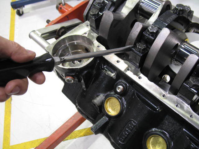
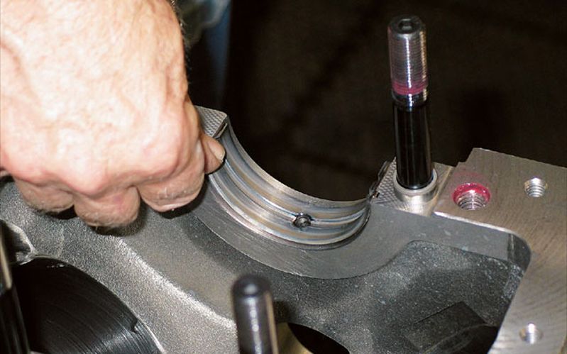
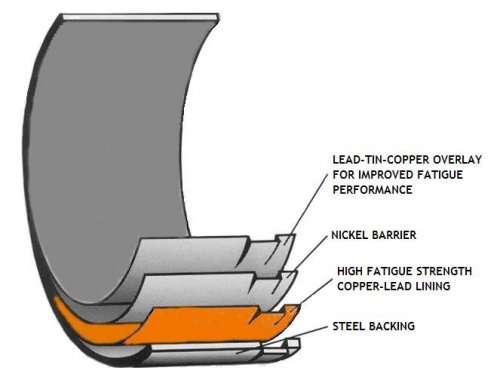
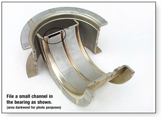
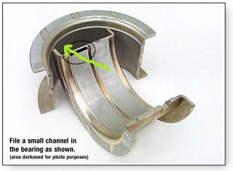
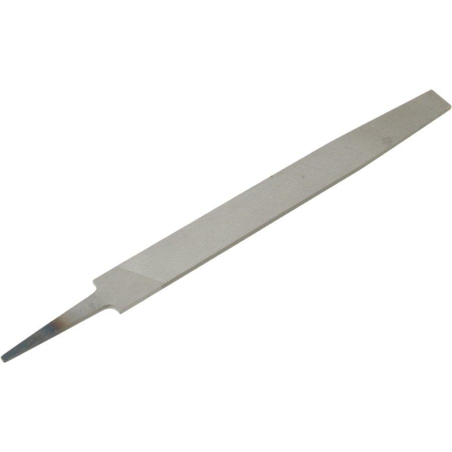
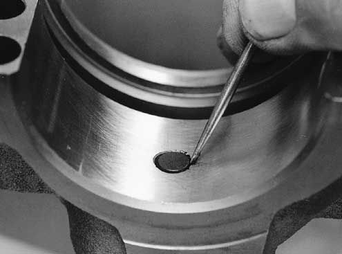
A simple modification to the upper thrust bearing may be beneficial in some engines. Install the upper thrust bearing in the block to determine which thrust face is toward the rear of the engine. Using a small, fine tooth, flat file, increase the amount of chamfer to approximately .040" (1 mm) on the inside diameter edge of the bearing parting line. Carefully file at the centrally located oil groove and stroke the file at an angle toward the rear thrust face only, as shown in the illustration below. It is very important not to contact the bearing surface with the end of the file. The resulting enlarged ID chamfer will allow pressurized engine oil from the pre-existing groove to reach the loaded thrust face. This additional source of oiling will reach the loaded thrust face without passing through the bearing clearance first (direct oiling). Since there may be a load against the rear thrust face, oil flow should be restricted by that load and there should not be a noticeable loss of oil pressure. This modification is not a guaranteed "cure-all". However, the modification should help if all other conditions, such as surface finish, alignment, cleanliness and loading are within required limits.
Other External Problems. Aside from the items already mentioned, there is another external problem that should be considered. Inadequate electrical grounds have been known to exacerbate thrust surface wear. Excessive current in the vehicle drive train can damage the thrust surface. It affects the thrust bearing as though the thrust surface on the crankshaft is not finished properly finished (too rough). Excessive voltage in the drive train can be checked very easily. With the negative lead of a DVOM connected to the negative post of the vehicle battery and the positive lead on the transmission, there should be no more than .01 volts registering on the meter while the starter is turning over the engine. For an accurate test, the starter must operate for a minimum of four seconds without the engine starting. It is suggested to disable the ignition system before attempting this test. If the voltage reading observed is found to be excessive, add and/or replace negative ground straps from the engine to the vehicle frame and transmission to frame until the observed voltage is .01 volts or less. Note: Some systems may show a reading of .03volts momentarily but yet not exhibit a problem. For added assurance, it is a good idea to enhance the drive train grounding with larger battery cables or additional ground straps.
A special thank you goes out to Dennis Madden of ATRA, Dave Hagen of AERA, Ed Anderson of ASA, Roy Berndt of PERA and John Havel of AE Clevite for their contributions to this article.
The AERA Technical Committee
March 1998 - TB 1465R
Crankshaft Thrust Bearing Failure:
Causes and Remedies
Although thrust bearings run on a thin film of oil, just like radial journal (connecting rod and main) bearings, thrust bearings can't support nearly as much load. While radial bearings can carry loads measured in thousands of pounds per square inch of projected bearing area, thrust bearings can only support loads of a few hundred pounds per square inch.
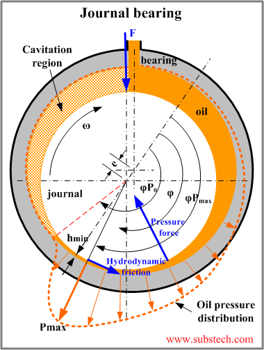
Radial journal bearings develop their higher load capacity from the way the curved surfaces of the bearing and journal meet to form a wedge. Shaft rotation pulls oil into this wedge-shaped area of the clearance space to create an oil film which actually supports the shaft.
Thrust bearings typically consist of two flat mating surfaces, with no natural wedge shape in the clearance space to allow an oil film to form, and support the load.
Conventional thrust bearings are made by adding flanges at the ends of a radial journal bearing. This provides ease in assembly and has been used successfully for many years. Both teardrop or through grooves on the flange face, and wedge shaped ramps at each parting line, allow oil to enter between the shaft and bearing surfaces.
But the surface of the shaft and the vast majority of bearing surfaces are flat. This flatness makes it more difficult to create and maintain an oil film. For example, suppose two gauge blocks had a thin film of oil on them. If you were to press them together with a twisting action, the blocks would stick together.
This is similar to what happens when a thrust load is applied to the end of a crankshaft: Oil squeezes out from between the shaft and bearing surfaces. If there's too much load, the oil film collapses and the surfaces want to stick together, which causes a wiping action, and ultimately, bearing failure.
This is why many heavy-duty diesel engines use separate thrust washers, each with a contoured face: to enable them to support higher thrust loads. These thrust washers either have multiple tapered ramps and relatively small flat pads, or they have curved surfaces that follow a sine-wave contour around the outer edge.
Recent Developments
In the past few years, some new automotive engine designs have included contoured thrust bearings. This change enables them to carry higher thrust loads imposed by some of the newer automatic transmissions. Since it's impractical to use contoured faces on one-piece flanged thrust bearings, these new engine designs use either separate thrust washers, or a flanged bearing, which is a three-piece assembly.
Cause of Failure
Aside from the obvious causes, such as dirt contamination and misassembly, there are only three common factors which generally cause thrust bearing failures:
1. Poor crankshaft surface finish
2. Misalignment
3. Overloading
Surface Finish
Crankshaft thrust faces are difficult to grind because they are done using the side of the grinding wheel. Grinding marks left on the crankshaft face produce a visual swirl, or sunburst pattern. The scratches sometimes crisscross one another in a cross-hatch pattern similar to hone marks on a cylinder wall.
If these grinding marks are not completely removed by polishing, they will remove the oil film from the surface of the thrust bearing, much like multiple windshield wiper blades. A properly-finished crankshaft thrust face should have only very fine polishing marks that go around the thrust surface in a circular pattern.
Alignment
Under normal circumstances, a remanufactured crankshaft does not require grinding of the thrust face surfaces. There are, however, situations where grinding is necessary. One is the automatic oversize of a thrust flange main bearing, required by using undersized crankshaft main journals.
A second occurs when thrust surface wear (front and rear) is beyond allowable specifications. This situation often requires an oversize thrust flange bearing or washer, if one is available for that application. Under these conditions, the thrust face of the crankshaft will require oversize grinding. In this case, crankshaft end float should be calculated and determined prior to grinding additional material from the thrust face.
Grinding the thrust face of the crankshaft presents a challenge, because the crankshaft remanufacturer has to use the side of the grinding wheel, which is not specifically designed for metal surface removal.
In addition, keeping enough coolant between the thrust surface and the wheel (just as keeping oil for lubrication within the engine) is difficult, and that combination creates a danger of wheel loading and burn spots. The result: an inconsistent thrust surface. To avoid this situation, the grinding wheel must be dressed periodically, to maintain a 90° angle, perpendicular to the centerline of the grinding wheel. This transfers to the same 90° angle between the thrust surface and the centerline of the crankshaft.
During the grinding process, the grinding wheel must feed into the thrust face very slowly and be allowed to spark out completely. If the grinding wheel does not cut cleanly, it may create hot spots on the crankshaft, leading to a wavy, out-of-flat surface. It is important to avoid excessive grinding of the thrust surface; this procedure is intended primarily for surface clean up.
When Assembling Thrust Bearings:
• Tighten the main cap bolts to about 10 to 15 ft-lbs in order to seat the bearings; then loosen the cap bolts.
• Tap the main cap toward the rear of the engine with a soft faced hammer.
• Thread the main cap bolts in finger tight.
• Use a bar to force the crankshaft as far forward in the block as possible, to align the bearing rear thrust faces.
• While holding the crankshaft forward, tighten the main cap bolts to 10 to 15 ft-lbs.
• Complete tightening the main cap bolts to specifications in two or three equal steps.
This procedure should align the bearing thrust faces with the crankshaft, to provide the maximum bearing contact for load carrying.
Loading
A number of factors may contribute to wear and overloading of a thrust bearing, such as:
1. Poor crankshaft surface finish
2. Poor crankshaft surface geometry
3. External overloading due to:
a) Too much torque converter pressure.
b) Improper clutch release bearing adjustment.
c) Riding the clutch pedal.
d) Excessive crankshaft load pressure due to a malfunctioning front-mounted accessory drive.
NOTE: There are other, commonly-thought issues such as torque converter ballooning, the wrong flexplate bolts, the wrong torque converter, the pump gears being installed backward or the torque converter not installed completely. Although all of these problems will cause undue force on the crankshaft thrust surface, it will also cause the same force on the pump gears, since all of these problems will put equal force in both directions from the torque converter. So any of these conditions should also cause serious pump damage very quickly (within minutes or hours).
Diagnosing the Problem
By the time a thrust bearing failure becomes evident, the parts have usually been so severely damaged there's little if any evidence of the cause. The bearing is generally worn into the steel backing, which has severely worn the crankshaft thrust face as well. The following is a list of factors to consider while diagnosing the cause.
Engine-Related Problems
Is there evidence of distress anywhere else in the engine that would indicate a lubrication problem or foreign particle contamination?
Were the correct bearing shells installed, and were they installed correctly?
If the thrust bearing is in an end position, was the adjacent oil seal installed correctly? An incorrectly installed rope seal can cause enough heat to affect bearing lubrication.
Examine the front thrust face on the crankshaft for surface finish and geometry. This may give an indication of the original quality of the failed face.
Once you're satisfied that all potential internal sources have been eliminated, ask about potential external sources, such as overloading or misalignment.
Transmission Related Problems
Did the engine have a prior thrust bearing failure?
What external parts were replaced?
Were any performance modifications made to the transmission?
Was an additional cooler installed for the transmission?
Was the correct flexplate used? At installation, there should be at least 1/16" (1/8" preferred, 3/16" maximum) clearance between the flexplate and converter, to allow for converter expansion.
Was the transmission aligned to the engine properly?
Were all dowel pins in place?
Was the transmission-to-cooler pressure too high? If the return line has very low pressure compared to the transmission-to-cooler line, check for a restricted cooler or cooler lines.
If a manual transmission was installed, was the clutch release bearing adjusted properly?
What condition was the clutch release bearing in? A worn or overheated clutch release bearing that's adjusted properly may indicate the operator was "riding the clutch."
How does the Torque Converter Exert Force on the Crankshaft?
There are many theories on this subject, ranging from converter ballooning to spline lock. Most of these theories have little real basis, and rely little on fact.
The force on the crankshaft from the torque converter is simple: It's based on the same principle as a servo piston or any other hydraulic component: Pressure, multiplied by area, equals force.
The pressure part is easy: It's simply the internal torque converter pressure. The area is a little more tricky. The area that's part of this equation is the difference between the area of the front half of the converter and the rear half. The oil pressure does exert a force that tries to expand the converter like a balloon (which is why converter ballooning is often blamed); however, the forward force on the crankshaft occurs because the front of the converter has more surface area than the rear (the converter neck is open). This difference in area is equal to the area of the inside of the converter neck.
The most common scenario is the THM 400 used behind a big-block Chevy. General Motors claims this engine is designed to sustain a force of 210 pounds on the crankshaft. The outside diameter of the converter hub 1.873". Therefore, the area of the hub is 2.755 square inches. 210 pound of force, divided by this area offers an maximum torque converter pressure of 76 PSI.
The best place to measure this pressure is the outgoing cooler line at the transmission, because it's the closest point to the internal converter pressure. The pressure gauge must be teed in, to allow the cooler circuit to flow. Under normal driving conditions the pressure will not exceed the 76 psi limit based on these figures.
Causes for Excessive Torque Converter Pressure
There are two main causes for excess torque converter pressure: restrictions in the cooler circuit, and modifications or failures that cause high line pressure.
One step for combating restrictions in the cooler circuit is to run larger cooler lines. Another is to install an additional cooler in parallel with the original, rather than in series. This will increase cooler flow considerably. An additional benefit to running the cooler in parallel is it reduces the risk of overcooling the oil in the winter. The in-parallel cooler may freeze up under very cold conditions; however, the cooler tank in the radiator will still flow freely.
Modifications that can result in higher-than-normal converter pressure include using an overly heavy pressure regulator spring, or excessive cross-drilling into the cooler charge circuit. Control problems such as a missing vacuum line or stuck modulator valve can also create high pressure.
What Will Help Thrust Bearings Survive?
A simple modification to the upper thrust bearing may be beneficial in some engines. Install the upper thrust bearing in the block to determine which thrust face is toward the rear of the engine. Use a small, fine tooth, flat file to increase the chamfer on the inside edge of the bearing parting line to about 0.040" (1 mm).
Carefully file at the centrally located oil groove and stroke the file at an angle toward the rear thrust face only, as shown in the illustration. Avoid contacting the bearing surface with the end of the file. The enlarged chamfer will allow pressurized engine oil from the pre-existing groove to reach the loaded thrust face, without passing through the bearing clearance first (direct oiling).
Since there may be a load against the rear thrust face, oil flow should be restricted by that load, so there shouldn't be a noticeable loss of oil pressure. This modification is not a guaranteed cure-all, but it should help if all other conditions, such as surface finish, alignment, cleanliness and loading are within required limits.
NOTE: As with all modifications, it is important to find the original cause of the problem before making modifications. Failure to do so may result in a repeat failure.
Other External Problems
Aside from the items already mentioned, there is another external problem that should be addressed. Ground problems have been known to intensify thrust surface wear. Excessive current in the drivetrain can damage the thrust surface, which then affects the thrust bearing as though the thrust surface on the crank shaft isn't finished properly.
It's easy to check for excessive voltage in the drivetrain: Connect the negative lead of your DVOM to the negative post of the battery, and the positive lead to the transmission. You should see no more than 0.1 volts on your meter while the starter is cranking.
For an accurate test, the starter must operate for at least four seconds. It may be necessary to disable the ignition system so the engine won't start during the test.
If the voltage is excessive, check or replace the negative battery cable, or add ground straps from the engine to the frame, or the transmission to the frame.
Some systems may reach 0.3 volts momentarily without having a problem. For added assurance, improve the ground with a larger battery cable or additional ground straps.
Although the greatest current draw is usually while the starter is cranking, current in the drivetrain can occur while accessories are operating. That's why you should perform this voltage-drop test with the ignition on, and as many accessories operating as possible. Again, the threshold is 0.1 volt.
One final problem that may occur is current though the drivetrain, without measurable voltage. If the grounding problem is in the chassis but the engine and transmission ground is okay (or vice-versa), the vehicle may pass the test. What happens here is the ground circuit can be completed through the drive shaft and suspension.
To test this, measure the voltage drop with the drive shaft removed. Both the drivetrain and frame must pass the 0.1 volt test. This is where a ground strap from the engine or transmission to the frame does its best work.
Summary
As with most problems, rarely is one solution the answer for all examples. It is attention to detail and rebuild procedures that include many details that ensure success. The intent of this article is to include the most likely causes for crankshaft thrust failure, as well as dispel some of the myths and mysteries surrounding it.
http://www.thirskauto.net/Engine_Thrust_Bearings.html
http://www.aera.org/tech/tb1465r.htm
viewtopic.php?f=50&t=9409
http://www.stealth316.com/misc/clevite-77-rod-main-bearings.pdf
http://www.small-block-chevy.com/assemblyspec.html
http://www.4secondsflat.com/Thrust_bear ... lures.html
http://www.circletrack.com/techarticles ... to_04.html
http://www.popularhotrodding.com/tech/0 ... e_control/
http://www.circletrack.com/enginetech/c ... ce_basics/
http://www.enginebuildermag.com/Article ... ilure.aspx
https://www.thomasnet.com/products/crankshaft-repair-services-20921979-1.html
http://members.rennlist.com/v1uhoh/cranksha.htm
http://www.atra-gears.com/crankshaft/
http://www.chevyhiperformance.com/tech/ ... ance_info/
Why Engine Thrust Bearings Fail
Often, soon after an engine rebuild, premature engine thrust bearing failure occurs. We will discuss some of the major causes of these types of failures.
One of the most common causes of thrust bearing failures is the transmission torque convertor. When the overrunning clutch in a torque convertor becomes either seized or will not lock up in one direction, the stator does not provide it's normal function of directing the transmission fluid to create the proper torque multiplication required to drive the vehicle. When this happens, a large amount of the energy created is exhausted through the center of the torque convertor, creating excessive forward pressure. It is this pressure which causes the engine thrust bearing damage. When installing a new engine, it is wise to check the convertor your self, or have a qualified transmission rebuilder inspect it for over running clutch problems.
Improper installation of the torque convertor in the transmission front pump can also lead to bearing failure, as well as transmission failure.
Vehicles with standard transmissions may also experience this type of engine failure due to high clutch pressures, usually related to performance clutches with high spring pressures being installed. Riding the clutch can also cause thrust bearing failure on new engines. You must also ensure the clutch has adequate free play.
Symptoms of damage caused by excessive external pressure on the crankshaft vary on engines due to their design differences.
Small block Chev engines usually suffer catastrophic damage from excessive external pressures. In most cases the thrust bearing show signs of heavy rubbing on the thrust bearing. The most severe damage it on the other mains bearings, with the highest wear being on the center bearing, usually concentrated on the lower half of the bearing. The intermediate main bearings will have about half the wear of the center bearing, with the front and rear bearing showing little sign of problem.
Big block Chev engines, due to the rigidity of their crankshaft, will usually only destroy the thrust face of the thrust bearing, causing little damage to the other mains.
Engines with a center thrust bearing usually, as well as rubbing the thrust surface, will show signs of wear on the opposite sides of the crankshaft on the two intermediate bearings.
I have seen cases of thust bearing failure on small block Ford engines that do not seem have an apparant cause. Upon checking the inner part of the bearing that seats in the block, signs of scraping on the bearing were noticed. This is the result of the installer trying to install the bearing in the rear location instead of the center, where the thrust bearing is located in this type of engine.
Crankshaft Thrust Bearing Failure - Causes & Remedies
For years both transmission and engine rebuilders have struggled at times to determine the cause of crankshaft thrust bearing failures. In most instances, all of the facts concerning the situation are not revealed at the onset of the failure. This has led to each party blaming the other for the failure based only on hearsay or what some "expert" has termed the "cause". Some of those explanations have led to an argument, that ends up in litigation while the truth lingers uncovered in the background. This document is a group effort of combined information compiled by the Automotive Transmission Rebuilders Association (ATRA), the Automotive Engine Rebuilders Association (AERA), the Production Engine Rebuliders Association (PERA), the Automotive Service Association (ASA) and bearing manufacturers. This group of industry experts has assembled the following information to consider and offers solutions that may prevent a similar thrust bearing failure.
Background:
Although thrust bearings run on a thin film of oil, just like radial journal (connecting rod and main) bearings, they cannot support nearly as much load. While radial bearings can carry loads measured in thousands of pounds per square inch of projected bearing area, thrust bearings can only support loads of a few hundred pounds per square inch. Radial journal bearings develop their higher load capacity from the way the curved surfaces of the bearing and journal meet to form a wedge. Shaft rotation pulls oil into this wedge shaped area of the clearance space to create an oil film which actually supports the shaft. Thrust bearings typically consist of two flat mating surfaces with no natural wedge shape in the clearance space to promote the formation of an oil film to support the load.
Conventional thrust bearings are made by incorporating flanges, at the ends of a radial journal bearing. This provides ease in assembly and has been used successfully for many years. Either teardrop or through grooves on the flange, face and wedge shaped ramps at each parting line allow oil to enter between the shaft and bearing surfaces. However, the surface of the shaft, as well as the vast majority of bearing surfaces, are flat. This flatness makes it more difficult to create and maintain an oil film. As an example; if two gauge blocks have a thin film of oil on them, and are pressed together with a twisting action, the blocks will stick together. This is similar to what happens when a thrust load is applied to the end of a crankshaft and oil squeezes out from between the shaft and bearing surfaces. If that load is excessive, the oil film collapses and the surfaces want to stick together resulting in a wiping action and bearing failure. For this reason, many heavy-duty diesel engines use separate thrust washers with a contoured face to enable them to support higher thrust loads. These thrust washers either have multiple tapered ramps and relatively small flat pads, or they have curved surfaces that follow a sine-wave contour around their circumference.
Recent developments:
In the past few years some new automotive engine designs include the use of contoured thrust bearings to enable them to carry higher thrust loads imposed by some of the newer automatic transmissions. Because it’s not practical to incorporate contoured faces on one piece flanged thrust bearings, these new engine designs use either separate thrust washers or a flanged bearing which is a three piece assembly.
Cause of failure:
Aside from the obvious causes, such as dirt contamination and misassembly, there are only three common factors which generally cause thrust bearing failures. They are:
Poor crankshaft surface finish
Misalignment
Overloading
Surface finish:
Crankshaft thrust faces are difficult to grind because they are done using the side of the grinding wheel. Grinding marks left on the crankshaft face produce a visual swirl or sunburst pattern with scratches - sometimes crisscrossing - one another in a cross-hatch pattern similar to hone marks on a cylinder wall. If these grinding marks are not completely removed by polishing, they will remove the oil film from the surface of the thrust bearing much like multiple windshield wiper blades. A properly finished crankshaft thrust face should only have very fine polishing marks that go around the thrust surface in a circumferential pattern.
Alignment:
The grinding wheel side face must be dressed periodically to provide a clean, sharp cutting surface. A grinding wheel that does not cut cleanly may create hot spots on the work piece leading to a wavy, out-of-flat surface. The side of the wheel must also be dressed at exactly 90° to its outside diameter, to produce a thrust face that is square to the axis of the main bearing journal. The crankshaft grinding wheel must be fed into the thrust face very slowly and also allowed to "spark out" completely. The machinist should be very careful to only remove minimal stock for a "clean-up" of the crankshaft surface.
In most instances a remanufactured crankshaft does not require grinding of the thrust face(s), so the grinding wheel will not even contact them. Oversize thrust bearings do exist. Some main bearing sets are supplied only with an additional thickness thrust bearing. In most of those instances, additional stock removal from the crankshaft thrust face surface may be required. Crankshaft end float should be calculated and determined before grinding additional material from the thrust face.
Crankshaft grinding wheels are not specifically designed for use of the wheel side for metal removal. Grinding crankshaft thrust faces requires detailed attention during the procedure and repeated wheel dressings may be required. Maintaining sufficient coolant between the grinding wheel and thrust surface must be attained to prevent stone loading and "burn" spots on the thrust surface. All thrust surface grinding should end in a complete "spark out" before the grinding wheel is moved away from the area being ground. Following the above procedures with care should also maintain a thrust surface that is 90° to the crankshaft centerline.
When assembling thrust bearings:
Tighten main cap bolts to approximately 10 to 15 ft.lb. to seat bearings, then loosen.
Tap main cap toward rear of engine with a soft faced hammer.
Tighten main cap bolts, finger tight.
Using a bar, force the crankshaft as far forward in the block as possible to align the bearing rear thrust faces.
While holding shaft in forward position, tighten main cap bolts to 10 to 15 ft.lbs.
Complete tightening main cap bolts to specifications in 2 or 3 equal steps.
The above procedure should align the bearing thrust faces with the crankshaft to maximize the amount of bearing area in contact for load carrying.
Loading:
A number of factors may contribute to wear and overloading of a thrust bearing, such as:
1. Poor crankshaft surface finish.
2. Poor crankshaft surface geometry.
3. External overloading due to.
a) Excessive Torque converter pressure.
b) Improper throw out bearing adjustment.
c) Riding the clutch pedal.
d) Excessive rearward crankshaft load pressure due to a malfunctioning front mounted accessory drive.
Note: There are other, commonly-thought issues such as torque converter ballooning, the wrong flexplate bolts, the wrong torque converter, the pump gears being installed backward or the torque converter not installed completely. Although all of these problems will cause undo force on the crankshaft thrust surface, it will also cause the same undo force on the pump gears since all of these problems result in the pump gear pressing on the crankshaft via the torque converter. The result is serious pump damage, in a very short period of time (within minutes or hours).
Diagnosing the problem:
By the time a thrust bearing failure becomes evident, the parts have usually been so severely damaged that there is little if any evidence of the cause. The bearing is generally worn into the steel backing which has severely worn the crankshaft thrust face as well. So how do you tell what happened? Start by looking for the most obvious internal sources.
Engine related problems:
Is there evidence of distress anywhere else in the engine that would indicate a lubrication problem or foreign particle contamination?
Were the correct bearing shells installed, and were they installed correctly?
If the thrust bearing is in an end position, was the adjacent oil seal correctly installed? An incorrectly installed rope seal can cause sufficient heat to disrupt bearing lubrication.
Examine the front thrust face on the crankshaft for surface finish and geometry. This may give an indication of the original quality of the failed face.
Once you are satisfied that all potential internal sources have been eliminated, ask about potential external sources of either over loading or misalignment.
Transmission related problems:
Did the engine have a prior thrust bearing failure?
What external parts were replaced?
Were there any performance modifications made to the transmission?
Was an additional cooler for the transmission installed?
Was the correct flexplate used? At installation there should be a minimum of 1/16" (1/8" preferred, 3/16" maximum) clearance between the flex plate and converter to allow for converter expansion.
Was the transmission property aligned to the engine?
Were all dowel pins in place?
Was the transmission-to-cooler pressure checked and found to be excessive? If the return line has very low pressure compared to the transmission-to-cooler pressure line, check for a restricted cooler or cooler lines.
If a manual transmission was installed, was the throw out bearing properly adjusted?
What condition was the throw out bearing in? A properly adjusted throw out bearing that is worn or overheated may indicate the operator was "Riding The Clutch".
How does the torque converter exert force on the crankshaft?
There are many theories on this subject, ranging from converter ballooning to spline lock. Most of these theories have little real bases and rely little on fact. The force on the crankshaft from the torque converter is simple. It is the same principle as a servo piston or any other hydraulic component: Pressure, multiplied by area, equals force. The pressure part is easy; it’s simply the internal torque converter pressure. The area is a little trickier. The area that is part of this equation is the difference between the area of the front half of the converter and the rear half. The oil pressure does exert a force that tries to expand the converter like a balloon (which is why converter ballooning is probably often blamed), however, it is the fact that the front of the converter has more surface area than the rear (the converter neck is open) that causes the forward force on the crankshaft. This difference in area is equal to the area consumed by the inside of the converter neck. The most common scenario is the THM 400 used behind a big-block Chevy. General Motors claims that this engine is designed to sustain a force of 210 pounds on the crank shaft. The inside diameter of the converter hub can vary from 1.5 inches up to 1.64 inches. The area of the inside of the hub can then vary from 1.77 square inches to 2.11 inches. 210 pound of force, divided by these two figures offers an internal torque converter pressure of 119 psi to 100 psi, respectively. That is to say, that depending on the inside diameter of the hub, it takes between 100 to 119 psi of internal converter pressure to achieve a forward thrust of 210 pounds. The best place to measure this pressure is the out-going cooler line at the transmission because it is the closest point to the internal converter pressure available. The pressure gauge must be "teed" in so as to allow the cooler circuit to flow. Normal cooler line pressure will range from 50 psi to 80 psi , under a load in drive.
Causes for excessive torque converter pressure:
There are two main causes for excessive torque converter pressure: restrictions in the cooler circuit and modifications or malfunctions that result in high line pressure. One step for combating restrictions in the cooler circuit is to run larger cooler lines. Another, is to install any additional cooler in parallel as opposed to in series. This will increase cooler flow considerably. An additional benefit to running the cooler in parallel is that it reduces the risk of over cooling the oil in the winter timeâ€â€especially in areas where it snows. The in-parallel cooler may freeze up under very cold conditions, however, the cooler tank in the radiator will still flow freely. Modifications that can result in higher than normal converter pressure include using an overly-heavy pressure regulator spring, or excessive cross-drilling into the cooler charge circuit. Control problems such as a missing vacuum line or stuck modulator valve can also cause high pressure.
What will help thrust bearings survive? When a problem application is encountered, every effort should be made to find the cause of distress and correct it before completing repairs, or you risk a repeat failure.
A simple modification to the upper thrust bearing may be beneficial in some engines. Install the upper thrust bearing in the block to determine which thrust face is toward the rear of the engine. Using a small, fine tooth, flat file, increase the amount of chamfer to approximately .040" (1 mm) on the inside diameter edge of the bearing parting line. Carefully file at the centrally located oil groove and stroke the file at an angle toward the rear thrust face only, as shown in the illustration below. It is very important not to contact the bearing surface with the end of the file. The resulting enlarged ID chamfer will allow pressurized engine oil from the pre-existing groove to reach the loaded thrust face. This additional source of oiling will reach the loaded thrust face without passing through the bearing clearance first (direct oiling). Since there may be a load against the rear thrust face, oil flow should be restricted by that load and there should not be a noticeable loss of oil pressure. This modification is not a guaranteed "cure-all". However, the modification should help if all other conditions, such as surface finish, alignment, cleanliness and loading are within required limits.
Other External Problems. Aside from the items already mentioned, there is another external problem that should be considered. Inadequate electrical grounds have been known to exacerbate thrust surface wear. Excessive current in the vehicle drive train can damage the thrust surface. It affects the thrust bearing as though the thrust surface on the crankshaft is not finished properly finished (too rough). Excessive voltage in the drive train can be checked very easily. With the negative lead of a DVOM connected to the negative post of the vehicle battery and the positive lead on the transmission, there should be no more than .01 volts registering on the meter while the starter is turning over the engine. For an accurate test, the starter must operate for a minimum of four seconds without the engine starting. It is suggested to disable the ignition system before attempting this test. If the voltage reading observed is found to be excessive, add and/or replace negative ground straps from the engine to the vehicle frame and transmission to frame until the observed voltage is .01 volts or less. Note: Some systems may show a reading of .03volts momentarily but yet not exhibit a problem. For added assurance, it is a good idea to enhance the drive train grounding with larger battery cables or additional ground straps.
A special thank you goes out to Dennis Madden of ATRA, Dave Hagen of AERA, Ed Anderson of ASA, Roy Berndt of PERA and John Havel of AE Clevite for their contributions to this article.
The AERA Technical Committee
March 1998 - TB 1465R
Crankshaft Thrust Bearing Failure:
Causes and Remedies
Although thrust bearings run on a thin film of oil, just like radial journal (connecting rod and main) bearings, thrust bearings can't support nearly as much load. While radial bearings can carry loads measured in thousands of pounds per square inch of projected bearing area, thrust bearings can only support loads of a few hundred pounds per square inch.
Radial journal bearings develop their higher load capacity from the way the curved surfaces of the bearing and journal meet to form a wedge. Shaft rotation pulls oil into this wedge-shaped area of the clearance space to create an oil film which actually supports the shaft.
Thrust bearings typically consist of two flat mating surfaces, with no natural wedge shape in the clearance space to allow an oil film to form, and support the load.
Conventional thrust bearings are made by adding flanges at the ends of a radial journal bearing. This provides ease in assembly and has been used successfully for many years. Both teardrop or through grooves on the flange face, and wedge shaped ramps at each parting line, allow oil to enter between the shaft and bearing surfaces.
But the surface of the shaft and the vast majority of bearing surfaces are flat. This flatness makes it more difficult to create and maintain an oil film. For example, suppose two gauge blocks had a thin film of oil on them. If you were to press them together with a twisting action, the blocks would stick together.
This is similar to what happens when a thrust load is applied to the end of a crankshaft: Oil squeezes out from between the shaft and bearing surfaces. If there's too much load, the oil film collapses and the surfaces want to stick together, which causes a wiping action, and ultimately, bearing failure.
This is why many heavy-duty diesel engines use separate thrust washers, each with a contoured face: to enable them to support higher thrust loads. These thrust washers either have multiple tapered ramps and relatively small flat pads, or they have curved surfaces that follow a sine-wave contour around the outer edge.
Recent Developments
In the past few years, some new automotive engine designs have included contoured thrust bearings. This change enables them to carry higher thrust loads imposed by some of the newer automatic transmissions. Since it's impractical to use contoured faces on one-piece flanged thrust bearings, these new engine designs use either separate thrust washers, or a flanged bearing, which is a three-piece assembly.
Cause of Failure
Aside from the obvious causes, such as dirt contamination and misassembly, there are only three common factors which generally cause thrust bearing failures:
1. Poor crankshaft surface finish
2. Misalignment
3. Overloading
Surface Finish
Crankshaft thrust faces are difficult to grind because they are done using the side of the grinding wheel. Grinding marks left on the crankshaft face produce a visual swirl, or sunburst pattern. The scratches sometimes crisscross one another in a cross-hatch pattern similar to hone marks on a cylinder wall.
If these grinding marks are not completely removed by polishing, they will remove the oil film from the surface of the thrust bearing, much like multiple windshield wiper blades. A properly-finished crankshaft thrust face should have only very fine polishing marks that go around the thrust surface in a circular pattern.
Alignment
Under normal circumstances, a remanufactured crankshaft does not require grinding of the thrust face surfaces. There are, however, situations where grinding is necessary. One is the automatic oversize of a thrust flange main bearing, required by using undersized crankshaft main journals.
A second occurs when thrust surface wear (front and rear) is beyond allowable specifications. This situation often requires an oversize thrust flange bearing or washer, if one is available for that application. Under these conditions, the thrust face of the crankshaft will require oversize grinding. In this case, crankshaft end float should be calculated and determined prior to grinding additional material from the thrust face.
Grinding the thrust face of the crankshaft presents a challenge, because the crankshaft remanufacturer has to use the side of the grinding wheel, which is not specifically designed for metal surface removal.
In addition, keeping enough coolant between the thrust surface and the wheel (just as keeping oil for lubrication within the engine) is difficult, and that combination creates a danger of wheel loading and burn spots. The result: an inconsistent thrust surface. To avoid this situation, the grinding wheel must be dressed periodically, to maintain a 90° angle, perpendicular to the centerline of the grinding wheel. This transfers to the same 90° angle between the thrust surface and the centerline of the crankshaft.
During the grinding process, the grinding wheel must feed into the thrust face very slowly and be allowed to spark out completely. If the grinding wheel does not cut cleanly, it may create hot spots on the crankshaft, leading to a wavy, out-of-flat surface. It is important to avoid excessive grinding of the thrust surface; this procedure is intended primarily for surface clean up.
When Assembling Thrust Bearings:
• Tighten the main cap bolts to about 10 to 15 ft-lbs in order to seat the bearings; then loosen the cap bolts.
• Tap the main cap toward the rear of the engine with a soft faced hammer.
• Thread the main cap bolts in finger tight.
• Use a bar to force the crankshaft as far forward in the block as possible, to align the bearing rear thrust faces.
• While holding the crankshaft forward, tighten the main cap bolts to 10 to 15 ft-lbs.
• Complete tightening the main cap bolts to specifications in two or three equal steps.
This procedure should align the bearing thrust faces with the crankshaft, to provide the maximum bearing contact for load carrying.
Loading
A number of factors may contribute to wear and overloading of a thrust bearing, such as:
1. Poor crankshaft surface finish
2. Poor crankshaft surface geometry
3. External overloading due to:
a) Too much torque converter pressure.
b) Improper clutch release bearing adjustment.
c) Riding the clutch pedal.
d) Excessive crankshaft load pressure due to a malfunctioning front-mounted accessory drive.
NOTE: There are other, commonly-thought issues such as torque converter ballooning, the wrong flexplate bolts, the wrong torque converter, the pump gears being installed backward or the torque converter not installed completely. Although all of these problems will cause undue force on the crankshaft thrust surface, it will also cause the same force on the pump gears, since all of these problems will put equal force in both directions from the torque converter. So any of these conditions should also cause serious pump damage very quickly (within minutes or hours).
Diagnosing the Problem
By the time a thrust bearing failure becomes evident, the parts have usually been so severely damaged there's little if any evidence of the cause. The bearing is generally worn into the steel backing, which has severely worn the crankshaft thrust face as well. The following is a list of factors to consider while diagnosing the cause.
Engine-Related Problems
Is there evidence of distress anywhere else in the engine that would indicate a lubrication problem or foreign particle contamination?
Were the correct bearing shells installed, and were they installed correctly?
If the thrust bearing is in an end position, was the adjacent oil seal installed correctly? An incorrectly installed rope seal can cause enough heat to affect bearing lubrication.
Examine the front thrust face on the crankshaft for surface finish and geometry. This may give an indication of the original quality of the failed face.
Once you're satisfied that all potential internal sources have been eliminated, ask about potential external sources, such as overloading or misalignment.
Transmission Related Problems
Did the engine have a prior thrust bearing failure?
What external parts were replaced?
Were any performance modifications made to the transmission?
Was an additional cooler installed for the transmission?
Was the correct flexplate used? At installation, there should be at least 1/16" (1/8" preferred, 3/16" maximum) clearance between the flexplate and converter, to allow for converter expansion.
Was the transmission aligned to the engine properly?
Were all dowel pins in place?
Was the transmission-to-cooler pressure too high? If the return line has very low pressure compared to the transmission-to-cooler line, check for a restricted cooler or cooler lines.
If a manual transmission was installed, was the clutch release bearing adjusted properly?
What condition was the clutch release bearing in? A worn or overheated clutch release bearing that's adjusted properly may indicate the operator was "riding the clutch."
How does the Torque Converter Exert Force on the Crankshaft?
There are many theories on this subject, ranging from converter ballooning to spline lock. Most of these theories have little real basis, and rely little on fact.
The force on the crankshaft from the torque converter is simple: It's based on the same principle as a servo piston or any other hydraulic component: Pressure, multiplied by area, equals force.
The pressure part is easy: It's simply the internal torque converter pressure. The area is a little more tricky. The area that's part of this equation is the difference between the area of the front half of the converter and the rear half. The oil pressure does exert a force that tries to expand the converter like a balloon (which is why converter ballooning is often blamed); however, the forward force on the crankshaft occurs because the front of the converter has more surface area than the rear (the converter neck is open). This difference in area is equal to the area of the inside of the converter neck.
The most common scenario is the THM 400 used behind a big-block Chevy. General Motors claims this engine is designed to sustain a force of 210 pounds on the crankshaft. The outside diameter of the converter hub 1.873". Therefore, the area of the hub is 2.755 square inches. 210 pound of force, divided by this area offers an maximum torque converter pressure of 76 PSI.
The best place to measure this pressure is the outgoing cooler line at the transmission, because it's the closest point to the internal converter pressure. The pressure gauge must be teed in, to allow the cooler circuit to flow. Under normal driving conditions the pressure will not exceed the 76 psi limit based on these figures.
Causes for Excessive Torque Converter Pressure
There are two main causes for excess torque converter pressure: restrictions in the cooler circuit, and modifications or failures that cause high line pressure.
One step for combating restrictions in the cooler circuit is to run larger cooler lines. Another is to install an additional cooler in parallel with the original, rather than in series. This will increase cooler flow considerably. An additional benefit to running the cooler in parallel is it reduces the risk of overcooling the oil in the winter. The in-parallel cooler may freeze up under very cold conditions; however, the cooler tank in the radiator will still flow freely.
Modifications that can result in higher-than-normal converter pressure include using an overly heavy pressure regulator spring, or excessive cross-drilling into the cooler charge circuit. Control problems such as a missing vacuum line or stuck modulator valve can also create high pressure.
What Will Help Thrust Bearings Survive?
A simple modification to the upper thrust bearing may be beneficial in some engines. Install the upper thrust bearing in the block to determine which thrust face is toward the rear of the engine. Use a small, fine tooth, flat file to increase the chamfer on the inside edge of the bearing parting line to about 0.040" (1 mm).
Carefully file at the centrally located oil groove and stroke the file at an angle toward the rear thrust face only, as shown in the illustration. Avoid contacting the bearing surface with the end of the file. The enlarged chamfer will allow pressurized engine oil from the pre-existing groove to reach the loaded thrust face, without passing through the bearing clearance first (direct oiling).
Since there may be a load against the rear thrust face, oil flow should be restricted by that load, so there shouldn't be a noticeable loss of oil pressure. This modification is not a guaranteed cure-all, but it should help if all other conditions, such as surface finish, alignment, cleanliness and loading are within required limits.
NOTE: As with all modifications, it is important to find the original cause of the problem before making modifications. Failure to do so may result in a repeat failure.
Other External Problems
Aside from the items already mentioned, there is another external problem that should be addressed. Ground problems have been known to intensify thrust surface wear. Excessive current in the drivetrain can damage the thrust surface, which then affects the thrust bearing as though the thrust surface on the crank shaft isn't finished properly.
It's easy to check for excessive voltage in the drivetrain: Connect the negative lead of your DVOM to the negative post of the battery, and the positive lead to the transmission. You should see no more than 0.1 volts on your meter while the starter is cranking.
For an accurate test, the starter must operate for at least four seconds. It may be necessary to disable the ignition system so the engine won't start during the test.
If the voltage is excessive, check or replace the negative battery cable, or add ground straps from the engine to the frame, or the transmission to the frame.
Some systems may reach 0.3 volts momentarily without having a problem. For added assurance, improve the ground with a larger battery cable or additional ground straps.
Although the greatest current draw is usually while the starter is cranking, current in the drivetrain can occur while accessories are operating. That's why you should perform this voltage-drop test with the ignition on, and as many accessories operating as possible. Again, the threshold is 0.1 volt.
One final problem that may occur is current though the drivetrain, without measurable voltage. If the grounding problem is in the chassis but the engine and transmission ground is okay (or vice-versa), the vehicle may pass the test. What happens here is the ground circuit can be completed through the drive shaft and suspension.
To test this, measure the voltage drop with the drive shaft removed. Both the drivetrain and frame must pass the 0.1 volt test. This is where a ground strap from the engine or transmission to the frame does its best work.
Summary
As with most problems, rarely is one solution the answer for all examples. It is attention to detail and rebuild procedures that include many details that ensure success. The intent of this article is to include the most likely causes for crankshaft thrust failure, as well as dispel some of the myths and mysteries surrounding it.
Last edited by a moderator: