To rotating assy or not to rotating assy...

DorianL

solid fixture here in the forum
Staff member
Grumpy, here's a question for you:

Now that my block is out and I am going to detail it....

While it is out, I am also trying to decide if I should buy a forged assy from Ohio Crank to make a 421 + uptick boost... or leave the short block stock and reassemble as it was.

Is there any advantage to a forged rotating assy with a stock 400 block? Or is this a waste?

Thanks!

D.
 
What kind of RPM do you turn??? When you start to get over 4000 FPM Mean Piston Speed, then it's time to consider a forged assembly.

Check out this table for help with the Piston Speed.
viewtopic.php?f=99&t=3370
 
I never go over the 5600. That is where the rev limiter is set.

Main concern is that block...

I do have a high-nickel 4-bolt 350 in my shop... But 421 seems more apealing than 383.
 
After reading carefully through... concluding that it is best to save my nickels and dimes for an Ohio Crank short block. -amen-

The question is now: what to do with the current SBC 400 now that it's out? Overboring and forged pistons seems like throwing good money after bad...

I am definitely going to put a bigger oil pan on there and replace the oil pump...

Beyond that, any suggestions?

D.
 
DorianL said:
After reading carefully through... concluding that it is best to save my nickels and dimes for an Ohio Crank short block. -amen-

The question is now: what to do with the current SBC 400 now that it's out? Overboring and forged pistons seems like throwing good money after bad...
You could put it in your grandmothers car! :)

I am definitely going to put a bigger oil pan on there and replace the oil pump...

Beyond that, any suggestions?
First look further down the road, what do you ultimately want to build, at some point it may make since to go with aftermarket block, like the Dart SHP if at some point in the future you're going to exceed the OEM block capability. CNC block NE sells them for $1795 machined and ready to go. Dart says their good to 600 HP, but most comments I've seen would be higher.


D.
 
I remember suggesting a DART block once your power levels started to exceed about 500hp.
(yeah! this hobby can be a never ending money pit)
one reason I build mostly big block Chevy engines is the stock 4 bolt blocks (fairly common and reasonably cheap)easily support the 500-550 hp power levels most street strip cars have.


viewtopic.php?f=51&t=47

viewtopic.php?f=51&t=2229

http://www.automedia.com/Engine_Assembl ... 100901e1/1

http://www.automedia.com/Engine_Assembl ... 100901e2/1

http://www.automedia.com/Engine_Assembl ... 101001e3/1

watch the slide show, read the links, its a fairly well done speed course in the basics
- Piston Motion Basics -
Travel, Velocity, Acceleration, Vibration
The crankshaft, connecting rods, wristpins and pistons in an engine comprise the mechanism which captures a portion of the energy released by combustion and converts that energy into useful rotary motion which has the ability to do work. This page describes the characteristics of the reciprocating motion which the crankshaft and connecting rod assembly imparts to the pistons.

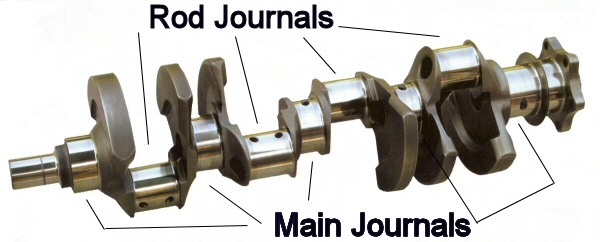
A crankshaft contains two or more centrally-located coaxial cylindrical ("main") journals and one or more offset cylindrical crankpin ("rod") journals. The V8 crankshaft pictured in Figure 1 has five main journals and four rod journals.

engine_technology_crankshaft_example.jpg

Figure 1

The crankshaft main journals rotate in a set of supporting bearings ("main bearings"), causing the offset rod journals to rotate in a circular path around the main journal centers, the diameter of which is twice the offset of the rod journals. The diameter of that path is the engine "stroke", which is the distance the piston moves from one end to the other end of its cylinder. The big ends of the connecting rods ("conrods") contain bearings ("rod bearings") which ride on the offset rod journals. ( For details on the operation of crankshaft bearings, Click Here; For details on crankshaft design and implementation, Click Here )

The small end of the conrod is attached to the piston by means of a floating cylindrical pin ("wristpin", or in British, "gudgeon pin"). The rotation of the big end of the conrod on the rod journal causes the small end, which is constrained by the piston to be coincident with the cylinder axis, to move the piston up and down the cylinder axis.

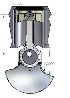
engine_technology_piston_motion_TDC.jpg

Figure 2: TDC

The following description explains the not-so-obvious characteristics of the motion which the crankshaft / conrod mechanism imparts to the piston.

Figure 2 shows a sectional end-view of a Crankshaft, Connecting rod and Piston (CCP) mechanism when the piston is at the furthest extent of its upward (away from the crankshaft) travel, which is known as the top dead center(TDC) position (even in upside-down and horizontal engines).

The furthest extent of the piston's downward (toward the crankshaft) travel is known as the bottom dead center(BDC) position.

In the CCP mechanism shown, the crankshaft has a 4.000 inch stroke and the center-to-center length of the conrod is 6.100 inches. The rod to stroke ratio (R / S) is the center-to-center length of the conrod divided by the stroke. In this example, the R/S is 6.100 / 4.000 = 1.525.

This ratio is important because it has a large influence on piston motion asymmetry (explained below), and on the resulting vibration and balance characteristics, as well as certain performance characteristics.

For purposes of this discussion, the extended centerline of the cylinder bore intersects the center of the crankshaft main bearing, and the wristpin is coincident with the cylinder centerline (defined as zero wristpin offset). Although the following descriptions apply strictly to configurations with zero wristpin offset, the general observations apply to nonzero offset configurations as well.

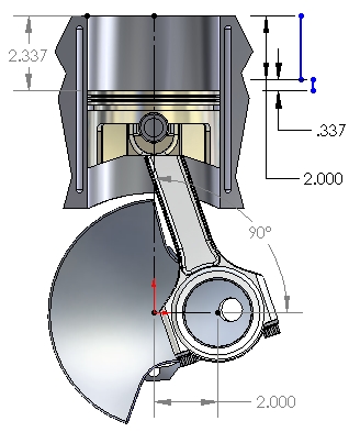
engine_technology_piston_accel_90.jpg

Figure 3: 90° After TDC

It is important to understand that the motion of the piston within 90° before and after TDC is not symmetric with the motion 90° before and after BDC. The rotation of the crankshaft when the crankpin is within 90° of TDC moves the piston substantially more than half the stroke value. Conversely, the rotation of the crankshaft when the crankpin is within 90° of BDC moves the piston substantially less than half the stroke value. This asymmetry of motion is important because it is the source of several interesting properties relating to the operation, performance and longevity of a piston engine.

Figure 3 shows the subject CCP with the crankpin rotated 90° past TDC. Note that the piston has moved over 58% of its total stroke (2.337 inches). That is because in addition to the 2.000" (half-stroke) downward motion of the crankpin (motion projected onto the vertical plane), the crankpin has also moved horizontally outward by 2.000", putting the conrod at an angle with the vertical plane.

The cosine effect of that conrod angle functionally shortens the projected length of the conrod in the vertical plane by 0.337", from 6.100" to the 5.763" shown in the picture. This dynamic "shortening" of the conrod has the effect of adding 0.337" to the 2.000" of downward motion imparted by the crankpin rotation, as illustrated by the two vertical blue lines in Figure 3.

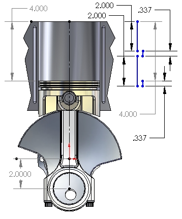
engine_technology_piston_accel_180.jpg

Figure 4: 180° After TDC

Now, since the piston has already moved about 58% of the stroke during the first 90° of crank rotation, it stands to reason that during the next 90° of crank rotation (to BDC) the piston will only have to travel the remaining 42% of the stroke to reach BDC, as shown in Figure 4.

The reason is that as the crank rotates toward BDC, the crankpin also moves horizontally back toward the center of the cylinder and "restores" the effective length of the rod. That cosine-effect "lengthening" of the conrod opposes the downward movement of the piston, subtracting 0.337 from the half-stroke of vertical motion produced from 90° to BDC. That effect is illustrated by the lower two vertical blue lines in Figure 4.

Clearly then, when the crankshaft is in any position other than TDC or BDC, the axis of the connecting rod is no longer parallel to the centerline of the cylinder (the line along which the piston, wristpin and small end of the rod are constrained to move). Therefore, the "effective length" of the conrod at any point other than TDC or BDC is the actual conrod center-to-center length multiplied by the cosine of the angle between the rod and the cylinder centerline. It is clear that the dynamic change in the conrod effective length adds to and subtracts from the purely sinusoidal motion caused by crankpin rotation.

engine_technology_piston_motion_half.jpg

Figure 5: Half-Stroke


Figure 5 shows that, with the R / S in this CCP example (1.525), the half-stroke position of the piston occurs at about 81° crank rotation after TDC. The rapid change in volume of the combustion chamber after the TDC position has some interesting ramifications with respect to the P-V diagram and thermal efficiency (discussed on a different page).


(Note: If you believe that installing longer connecting rods will increase an engine's stroke, there's no need for you to go any further on this page, or on this entire site, for that matter.)


[paste:font size="4"]Velocity and Acceleration page, or any basic calculus text, such as ref-1:2:39) .)

engine_technology_piston_motion_Vmax.jpg

Figure 6: Maximum Velocity

For simplicity of explanation, I have chosen to use crank rotation as the reference for these graphs. Typically, one is interested in the rate of change of piston position with respect to time, which would yield velocity in inches or feet per second, and the value would depend on the rotation speed of the crankshaft.

It is obvious that, as the piston moves from TDC to BDC and back, the velocity is constantly changing, and that the piston velocity is zero at TDC and BDC. The value and location of the maximum velocity with respect to crank rotation (the maximum slope of the position curve) are strongly influenced by the R / S ratio.

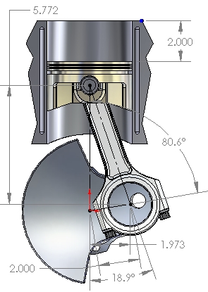
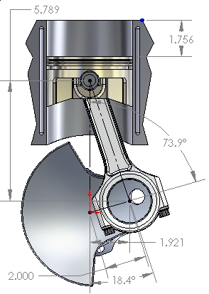
Figure 6 shows the location of the point of maximum piston velocity, in crankshaft degrees before and after TDC, for the configuration used in this example (4-inch stroke, 6.100" rod length, R / S = 1.525). At that position (73.9° before and after TDC), the piston has traveled only 43.9% (1.756") of the total stroke (4.000"). For this configuration (R / S = 1.525), at 4000 RPM, the peak piston velocity is 4390 feet per minute. For a longer stroke with the same R / S, the location of peak piston velocity would be the same, but the actual value of that velocity would be higher (at the same RPM, of course).

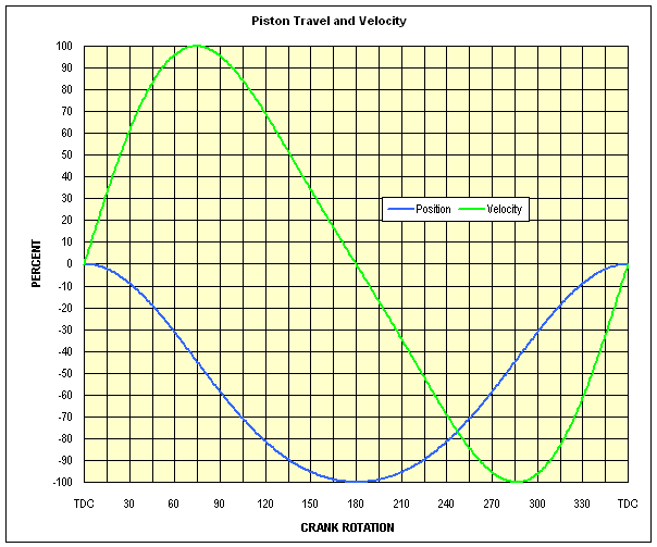
Figure 7 shows graphs of piston position and of instantaneous velocity as a function of crankshaft rotation. The blue line ("position") shows piston location (as a % of stroke) at any point during one rotation of the crankshaft. The blue line is artificially oriented so as to show position in an intuitive sense (top, bottom), therefore the "-" signs shoud be ignored with respect to position. The green velocity line shows the relative speed of the piston (as a % of maximum) at any point. Velocity with a "plus" sign is motion TOWARD the crankshaft; velocity with a "minus" sign is motion AWAY from the crankshaft.

Note again that at TDC and again at BDC, the piston velocity is zero, because the piston reverses direction at those points, and in order to change direction, the piston must be stopped at some point.

Note also that the position plot (blue) shows that, for this R / S ratio ( 1.525 ), the 50% stroke positions occur at approximately 81° before and after TDC (as illustrated in Figure 5 above). The velocity plot (green line) shows the maximum piston velocities occur at about 74° before and after TDC (as illustrated in Figure 6 above). The velocity line also shows that the piston velocity at any rotation point from TDC up to the maximum velocity is greater than at the same number of degrees before BDC. For example, compare the velocity at 30° after TDC (62%) with the velocity at 30° before BDC (34%).

engine_technology_piston_motion_g1.gif


Figure 7

The profile of the velocity curve, and therefore the location of the maximum velocity, are both influenced by the R / S ratio. As the rod gets shorter with respect to stroke (a smaller R / S ratio), two interesting things happen which can have important effects on cylinder filling: (1) the point of maximum piston velocity moves closer to TDC, and (2) the piston moves away from TDC faster, creating a stronger intake pulse. The location of maximum piston velocity influences the design of camshaft lobe profiles (especially intake) in order to optimize the intake event in a particular speed range, and can have an influence on the intake characteristics with regard to the strength and shaping of the intake pulse for ram tuning.

[paste:font size="4"]Velocity and Accelerationfor a more thorough explanation.)

It is clear from Figure 7 that the piston velocity is constantly varying with respect to a constant change in angular crankshaft position (rotation). Therefore, In order to move from the zero-velocity point (TDC) to the maximum velocity point, the piston must be subjected to a large acceleration function which varies with the angular rotation of the crankshaft.

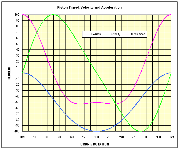
Figure 8 shows the acceleration, velocity and position plots for the example CCP under discussion. (All numeric values presented are for the 1.525 R / S in this example.)

engine_technology_piston_motion_g2.gif

Figure 8

The maximum positive value of acceleration (100%) occurs at TDC. Between TDC and maximum piston velocitty (74° in this case), acceleration is positive but decreasing toward zero (the piston velocity is still increasing but less rapidly). At maximum piston velocity (74° at this R / S ), the piston stops speeding up and begins to slow down. At that point, the acceleration changes direction (from a "plus" number to a "minus" number), and in so doing, momentarily passes through zero.

At this R / S, the maximum negative acceleration does not occur at BDC, but about 40° either side of BDC. The value of this maximum negative acceleration is only about 53% of the maximum positive acceleration seen at TDC. The acceleration at BDC is only 49% of the TDC maximum. The acceleration from max piston velocity (74°) to BDC is negative, and that acceleration is slowing the piston to zero velocity. Therefore, it might be (incorrectly) called deceleration. However, that same negative acceleration is applied to the piston after BDC and is causing its velocity to increase.

The zero acceleration point occurs (by definition) at the point of maximum piston velocity (74° B/A TDC), where velocity is reversing direction, but the rate of change of velocity (the slope of the curve) is zero.

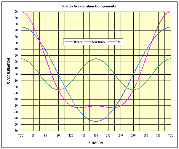
The somewhat odd shape at the bottom of the total piston acceleration (magenta) curve is the result of the fact that the total piston acceleration is the sum of several orders of acceleration, the first two being the most significant. The two major orders which combine to produce this total acceleration profile are important because they can produce significant vibration challenges to the engine designer (covered in Crankshafts).

Figure 8 shows the same total piston acceleration curve (magenta line) shown in Figure 7, along with the two significant orders of piston accelerations which combine to produce that curve. The total piston acceleration curve (magenta) is the sum of the two separate accelerationorders: primary (blue) and secondary (green).

engine_technology_piston_motion_g3.gif

Figure 8

As explained in Piston Motion above, the piston motion in the first 90° of rotation consists of the sum of the effect of the half-stroke motion of the crankpin projected onto the vertical plane (2.000") and the effect of the apparent 0.337" "shortening" of the rod length projected onto the vertical plane. The second 90° of rotation also produces a half-stroke motion in the vertical plane, but the cosine-effect lengthening of the conrod in the vertical plane produces 0.337" motion which subtracts from the half-stroke.

The primary acceleration (blue line) is the result of the piston motion produced by the component of crankpin movement projected onto the vertical plane. This curve is a sinusoid which repeats once per revolution of the crankshaft (first order) and comprises the majority of the acceleration. Note that the primary acceleration curve crosses zero at the 90° rotation points and peaks at TDC and BDC.

The secondary acceleration (green line) is the result of the additional piston motion caused by the cosine-effect dynamic length-change of the conrod. This motion adds to the piston movement between TDC and the max velocity point and subtracts from the piston motion between the max velocity point and BDC. This curve is also sinusoidal and repeats twice per crankshaft rotation (second order) and crosses zero at the 45°, 135°, 225° and 315° rotation points. The total piston acceleration at any point is the sum of the values of the primary and secondary acceleration curves.

Contemporary piston engines tend to have R / S ratios in an approximate range of 1.5 to 2.0. Note that a rod / stroke ratio less than 1.3 is, for practical applications, not possible due to physical constraints such as the need for piston rings and a wristpin, sufficient piston skirt length, and the inconvenience of having the piston contact the crankshaft counterweight, not to mention the excessive side load such a small ratio would produce.

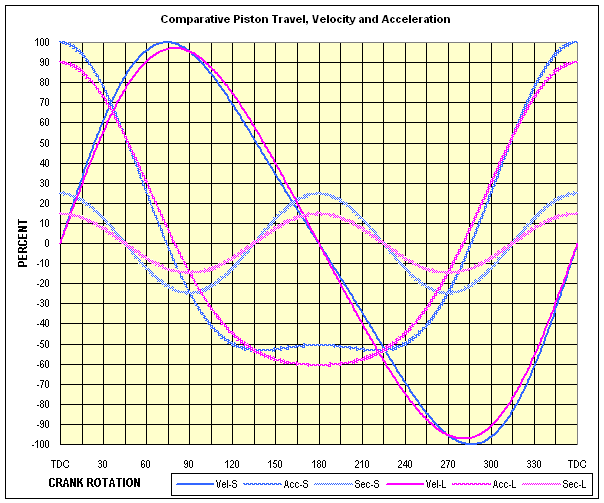
Here are two practical examples comparing the effects of R / S on acceleration and velocity (illustrated in Figure 9below). In a Lycoming IO-360 (and IO-540) the rod length is 6.75" and the stroke is 4.375", for a ratio of 1.543, close to the low end of the spectrum in contemporary design. At the other end of that spectrum, the connecting rod on a typical (circa 2007) 2.4-liter Formula-1 V8 engine is about 4.010" long, what your average race-engine mechanic would call a "very short rod". However, the stroke in the F1 engine is in the vicinity of 1.566", which produces a very large R / S ratio of 2.56.

engine_technology_piston_motion_g4.gif


Figure 9

The graph in Figure 9 clearly shows the effect of large and small R / S ratios. It is quite clear that the engine with the very small R / S ratio of 1.543 (the "long" 6.75 inch conrod, the blue velocity and acceleration curves) has a substantially higher peak acceleration (10%), a higher secondary acceleration, a higher (3%) peak velocity, an earlier (5 crank degrees) velocity peak location, and the very distinct acceleration reversal around BDC, confirming the substantial secondary vibration component.

Compare that to the large 2.56 R / S ratio (the "short" 4.01 inch conrod) magenta curves, showing a substantially lower (10%) peak acceleration, a lower secondary acceleration, a later and slightly lower (3%) peak velocity, and a total acceleration curve which is closer to symmetric, confirming the substantially-reduced secondary vibration component. Figure 9 also clearly demonstrates the absurdity of discussing conrod length as an absolute.

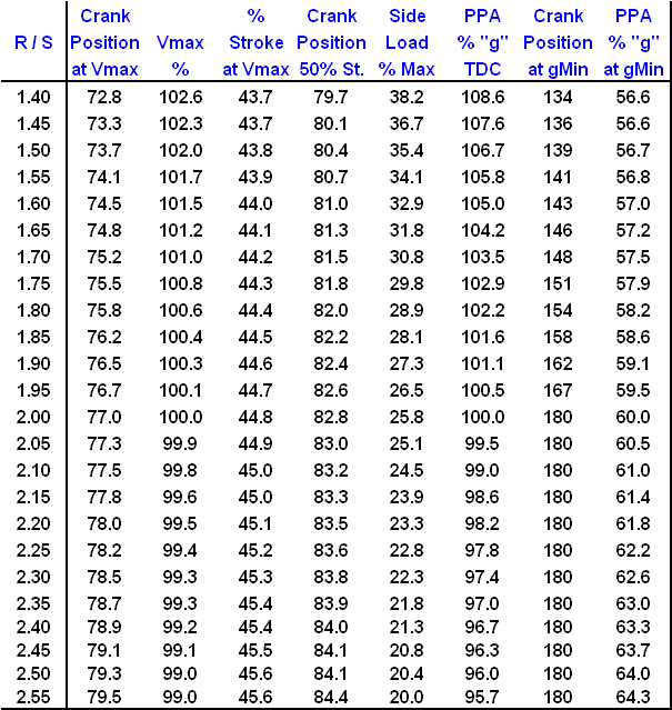
Figure 10 is a chart listing the main effects of R / S ratios varying from 1.40 to 2.55. I chose R / S = 2.0 to be the reference point for these comparisons of Vmax %, PPA max-positive %, and PPA max-negative % because that ratio is the lowest at which the maximum negative acceleration occurs at BDC. Notice that at R / S ratios above 2.00, the acceleration curve becomes more symmetric, but the peak velocity does not change much at all.

engine_technology_piston_motion_g5.gif

 
Last edited by a moderator:
Roger that. Will chat with JT to see how he mananged to ship those blocks over.

Still, other than oil pan, oil pump... Is there anything else you'd do to the stock block?

This will be in the meantime as I save up for a performance block... Geez, I can't believe I'm taking it to this level.

D.
 
I do a slight inclination not to spend another dime on the old 400 and simply focus all expenses on next and final step up. We'll decide based on $$$ and turnaround time.
 
your petty much wasting money if you try to upgrade the stock O.E.M. 400 4 bolt block with SPLAYED MAIN CAPS, like the guys occasionally do on the O.E.M. 2 bolt 400 blocks, because the basic block web and cylinder wall thickness/strength is just not there., the minimal gain in strength is vastly out weighed by the cost over your current factory 4 bolt config.
personally ID suggest selling the whole short block and using the cash as a down payment on your new DART block based SBC short block, and Id suggest a 4340 steel balanced rotating assembly, in a 406-427 displacement,8:1 cpr , forged pistons,7/16" rod bolt rods, and a 7-8 quart baffled oil pan matching your cars frame

http://www.lewisracingengines.com/

http://www.ohiocrank.com/chev_sb_shortb.html
 
Well, I agree with you 100% that the next step is an aftermarket block.

I have two options:

Option A:
Sell the short block.

I can't imagine that I will get much out of it... $2-300? And it will take me at least 6 months to save up for an SHP + rotating assy. That 1/2 a year of no loud pedal!

Option B:
Slap the old 400 back together. Don't go wild on it. In the meantime save my nickels and dimes for what I am really after. The only thing I think I will change now is the oil pan.

What do you gentlemen think?
 
Most people would probably try reassembly and driving the car for now but
just keep in mind theres some slight risk of the current short block rapidly dis-assembling it self at some point and that puts a significant risk of damaging the heads,intake etc.
I know exactly how your feeling, Ive had my 1985 vette up on jack stands for over a year now as I try to get the required parts assembled to install the big block engine Ive got partially built for it, and its matched drive train......not much progress because family problems keep draining the cash required.
 
grumpyvette said:
...just keep in mind theres some slight risk of the current short block rapidly dis-assembling it self at some point...

LOLOLOL I hear ya!
 
E-mailed Lewis Racing.

The plan is clear... I'll get next to nothing for a 400 with no heads here. So I will button it up and be mindful that it could want to disassemble on me at some point.

In the meantime I will do two things:
- Save up my nickels and dimes for a Lewis Racing or Ohio Crank short block.
- Make everything else on chevy is robust: cooling, wiring, etc.

D
 
Corresponding with Lewis Racing. Clearly very knowledgable, very pleasant and helpful too. Decided to jump in feet first and get one of his short blocks.

Not sure if I even want to reassemble my old SBC400. It would be a waste of gaskets and oil and time slamming in and pulling back out. I'm on the edge on this one. There is a sixty (read 90?) day turn around on the short blocks. In the meantime I could clean up engine bay work on wiring and change puppies on super...

Soooo, on the edge... Leaning toward making the 400 a relic.

Kinda bugs me to have chevy down for 60-90-?? Days? But it would kick ass at the races. ;-)
 
jteu2002 said:
you will need the 90 days to get ride off all the wirering you got hanging all over the place in your car

:D

Heheheh. While flaming chicken remains on jackstands, catch any fish lately?
 
many of us that have reached the same point in the hobby have gone one of two routes, most who still have a great deal of parts,go with the DART aftermarket block simply because they probably have a good deal of SBC related parts and experience building SBC engines that cost a good deal of cash and took years to accumulate.
some, guys had a cataclysmic engine failure at some point,or sold a car and most of their parts ,at some point, for various reasons,
(usually marriage, cash flow or kid related) leaving them with either few parts or a distrust of the BASIC SBC PLATFORM,
or a desire to build bigger engines, or as in my case they, get tired of building 400-468 Pontiac and mopars and seeing the Chevy guys get all the trick parts and cheap component prices , so they just decide to go, just throw in the towel, bite the bullet, and start over building BIG BLOCK CHEVY ENGINES,or BIG BLOCK MOPAR OR FORDS
theres a point at about 450-500 plus hp where many SBC guys rapidly come to realize the futility of using the stock production O.E.M. block on a SBC engine,most either have a major engine failure or have bearing problems.

related bits of info

viewtopic.php?f=51&t=3363

viewtopic.php?f=51&t=2919

viewtopic.php?f=51&t=2303

viewtopic.php?f=51&t=47

viewtopic.php?f=51&t=1458

viewtopic.php?f=51&t=1009
 
DorianL said:
jteu2002 said:
you will need the 90 days to get ride off all the wirering you got hanging all over the place in your car

:D

Heheheh. While flaming chicken remains on jackstands, catch any fish lately?

no fish no time to spend on the chicken need work on other cars to get some money to spend

some of us need extra jobs to pay for there hobby's especialy if there are more than one that costs
money :D
 
Back
Top