I found this article and this guy as put a lot of thought into making this work without buying a kit. I did try to get his permission to post this but at this time he still has not responded to my email that I sent on 5-23-13.The entire article is posted below, but if you want to see his website, the link is below.
http://www.rowand.net/Shop/Tech/LockupTCCWiring.htm
Lockup TCC Wiring (TCC=Torque Converter Clutch)
This page is all about what I learned about the wiring needed to control the lockup torque convert clutch (TCC) after I decided to swap the original TH400 transmission in my 1975 GMC Suburban for a TH700R4 transmission to gain the benefits of a modern overdrive transmission and help tame my "great for towing" 4.11 rear axle gears on the highway. As part of this project, I also had to build a custom Throttle Valve Cable Bracket so I could hookup the TV cable to the carburetor. This information applies in large measure to the TH200R4 transmissions, but not to any of the computer-controlled transmissions that came later - they are all controlled by the computer and the wiring is more or less just to all the sensors involved and is specific to the computer you have to use.
Overview
The only wiring work you need to do on these transmission is wire up the controls for the lockup feature on the torque converter. This can be accomplished with simple kits from several places or with custom wiring of your choice. The kits typically have two wires going into the transmission - one is power to the torque converter clutch and another is a ground connection. When you have power and a ground, the converter is "locked". When one or both are disconnected, the converter is unlocked. The kits typically have a vacuum switch, some basic wiring, perhaps a pressure switch to know what gear the transmission is in, and sometimes even a simple speed sensor to prevent lockup below a certain MPH. These kits are all "plug and play" simple, so you can just buy one and be done with it. Or you can figure it out and create your own kit - it's your choice and your money. Being the sort of "gotta do it my way" kind of guy that I am, I decided to do my wiring from scratch and figure out all the details along the way.
One thing of note is that some of the wiring is inside the transmission pan, so when you drain any remaining fluid by removing the pan to change the filter, that's the time to get the wiring done the way you want it. No sense doing that more than once.
Details
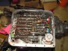
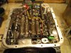
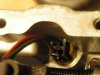
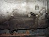
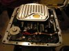
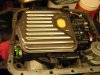
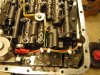
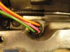
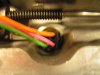
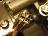
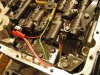
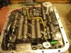
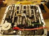
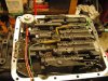
Here are some pictures of the wiring on my donor transmission as I received it. The first photo shows the wiring connector on the driver's side of the transmission with the three clipped wires coming out of it - look closely, it is there in the grime and dirt. It shows the three wires coming out of the wiring plug on the transmission and the basic location of the wiring plug in relation to the shift linkage. The next four photos show the internal wiring inside the transmission pan - there was quite a bit inside here on my donor transmission! The final photo shows the underside of the transmission case connector - the white plastic piece is clipped into the transmission housing and there are plus that go into it from the top and bottom - it's quite a complicated little piece!
It's important to know what all that wiring does and why it's there - because I'm going to change it to suit the needs I have after swapping this transmission into a non-computer-controlled vehicle. There are a total of four possible pressure switches, three possible wires coming into the transmission, and a solenoid to do the actual work of locking up the torque converter. Note that I said "possible" - not all transmissions used all of the pressure switches and wiring. In addition, there are two different style solenoids that were used in various applications.
For reference, I'm including a pretty detailed list of the wiring and switches inside my transmission. It had pretty much every possible wiring option and folks can use this to help ID what goes where for doing retrofit or swap applications. I had a heck of a time figuring this out from available information on the internet and eventually had to buy a factory manual for the year and model vehicle my donor transmission came from to confirm all the details. I'm posting it here for others to learn from my experience.
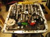
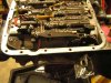
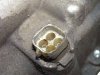
- The solenoid has the single red wire going to it and is next to the pressure switch with the single green connector. This solenoid is the single wire "self-grounding" style solenoid. Most swap applications I've seen (including kits from TCI, etc.) require using the two wire style solenoid with a separate ground wire that can be controlled - it's easier to do the wiring on the ground side of things in many situations.
The pressure switch with the single green connector is installed in the "TCC Signal" location and is a normally open unit that is self-grounding. I believe the contact is connected to ground whenever the TCC is engaged.
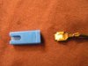
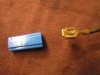
The pressure switch with the two blue connectors on it is installed into the "4th Clutch" location and is a normally open unit that is not grounded. The contacts are connected whenever the transmission is in 4th gear.
The pressure switch with the two green connectors on it is installed into the "4-3 Downshift" location and is a normally closed unit that is not grounded. I believe that the contacts are disconnected during the 4-3 downshift and I would assume this prevents problems with the TCC being locked up during the downshift.
The pressure switch with the two red connectors on it is installed into the "3rd Clutch" location and is a normally open unit that is not grounded. The contacts are connected whenever the transmission is in 3rd gear.
If you choose to not use any of the switches, they can be left in place, or removed and replaced with 1/8" NPT plugs. All four holes must have a switch or plug in them for the transmission to function, so double check stuff or you'll be removing the transmission pan and fixing it once the transmission is in the car - quite the messy experience. I opted to remove all but the "4th Clutch" switch and replace the others with 1/8" NPT plugs - the switches seemed to work and were nifty enough to save for other possible projects. Plus, removing the "TCC Signal" switch makes it easier to get at one of the bolts for the solenoid, which I had to remove to see about changing to the two-wire style solenoid from my original one-wire self-grounding style solenoid.
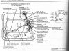
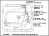
Here's the TCI internal wiring diagram for reference. Note that is shows pipe plugs in the three unused pressure switch locations. The labeling is done in a somewhat confusing way, but it does contain useful information, so I'm including it here for reference purposes.
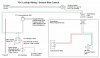
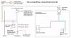
Here was my first cut at a wiring diagram that should work similar to the TCI kit, plus this will have an indicator light and the ability to force the torque converter to lock up in any gear. Like most other kits, it controls everything on the ground side of the system, though the control switch does toggle things completely off when in the center OFF position. I like having that control, but it's not strictly needed. It does offer a nice safety feature in case of electrical system problems down inside the transmission, so I would prefer to do it this way. If this added niftiness isn't important to you, it's possible to substitute a SPDT center-off switch and run the power wire straight out to the solenoid with a wire heading up to the LED indicator as shown here. Since SPDT center-off switches might be easier to find than DPDT center-off switches this could be a viable option for some folks.
- If you have the older GM style cruise control where the power goes through the brake switch first and then out to the cruise system, the cruise control will still work if you simply splice into the existing switch wiring as shown. If you have a newer style system, then you will need to add a second switch for the TCC or wire up a suitable relay system to drive things properly.
The indicator LED will likely need a dropping resistor of the proper size for whatever LED you choose and the overall brightness you want. You could even get tricky here and rig up something that would make the LED less bright when the dash lights were on, but that's a different topic entirely and would add some extra complexity. Not too hard, so I'm just tossing it in here as a thought.
The vacuum switch in the "TCC Automatic Lockup" wiring ensures that the TCC unlocks in situations of low or no vacuum. Since it's hooked to a ported vacuum source, this means the switch is open at idle and when the engine is under heavy load - exactly when you want the TCC to be unlocked. The factory switches I've seen have a small vacuum restrictor/delay valve inline just before the actual switch, and this helps delay lockup until you have a few seconds of good, stable vacuum going to the switch. So long as the vacuum rating of the switch and the delay time on the valve are reasonably matched to your engine combination, this should result in the effect of only locking up the TCC when the engine is under stable operation. TCI's kit uses an adjustable vacuum switch to enable you to fine-tune this.
The brake switch makes sure that the TCC is unlocked when you step on the brake - this is important in "panic stop" situations where you jam on the brakes and might lock the tires. It also ensures that the TCC is off when you at sitting at a stoplight.
After creating that basic diagram and pouring over the manuals, I found a few interesting details that kept my idea hamster going for a while. This is more stuff to think about before deciding on what wiring to use for your transmission.
- The original wiring diagrams show a "4-3 Downshift Switch" that on my transmission was a normally closed switch. The shop manual does not speak to this, but based on the wiring and what details I can find, it seems to indicate that this switch opens during the 4-3 downshift, and thus unlocks the TCC in this case. I can't decipher the timing on this to know if it matters to wire the 4-3 downshift switch in series with the 4th gear switch in an retrofit application, but if it got the TCC to unlock a touch sooner, then it might be interesting, useful, and simple to add this into the wiring for the "TCC Automatic Lockup" wiring. If you did this, you could splice the "4-3 Downshift Switch" into the green wire that goes between the 4th Gear switch and terminal D on the transmission case connector. Or you could splice it in between the 4th Gear Switch and the solenoid to have it act in both positions of the dash switch. This is provided mainly as food for thought - I'm not sure enough to say what exact effect this would have once the vehicle was being driven. If someone knows how this switch actually works inside the transmission and under what conditions this switch would be activated, feel free to drop me a line and explain it so I can post the details here.
The "TCC Signal Switch" appears to be a self-grounding normally open pressure switch that makes contact to ground whenever the TCC hydraulic system has pressure. If so, this is a much more interesting way to hook up the TCC Lockup Indicator. In the wiring above, the indicator light really means "we have applied electrical power to the TCC lockup solenoid", not "the TCC is locked up". If this switch does what I think it does, it could be used to drive the indicator light directly, in which case the indicator light would mean "the TCC lockup system has hydraulic pressure applied to it" - a much more useful piece of information if something goes awry in the future, such as the solenoid crapping out or the TCC hydraulic system having problems. The indicator light would reflect the reality inside the transmission much more directly. As with the "4-3 Downshift Switch" above, this is more food for thought, and if someone knows how this actually works inside the transmission and under what conditions this switch would be activated, feel free to drop me a line and explain it so I can post the details here.
There are only three wires that go into the transmission case connector, even though it looks to have provisions for four. The case connector on mine has a solid plug in the "C" location, thus preventing use of the fourth terminal. This presents a problem if you want to try and use the "TCC Signal Switch" idea above, because the original wiring diagram already uses all three connections. You can either dump the "force TCC lockup in any gear" feature, or do some creative rewiring to move the control to the positive side of the system. This requires the use of a one-wire self-grounding solenoid, but other than that and some wiring differences, it's basically the same.
The "TCC Always On" wiring in the diagram above really means "always on" - the TCC always on unless you step on the brakes. That means you could get an unpleasant surprise if the TCC is locked and you step on the brakes, stop the vehicle, then let off the brakes. At that point the TCC will try to engage wit the vehicle stopped, running, and in gear. The engine will likely stall or at least buck as the TCC will try to lock even though you are not moving yet. "ON" really does mean "ON" in this case! One idea to fix this is to rig up a low-speed switch of some kind to open the circuit below, say, 10 MPH. It would be interesting to wire it into this system and see how it worked. I'd bet acceleration would be sluggish, and the TCC could have longevity issues (just theorizing here, no hard proof), but it would certainly be a nice safety feature for when others might drive your vehicle - aka, the wife. Don't say you weren't warned!
Another route to "idiot proof" the system would be to wire the vacuum switch inline with the power wire so that the brake switch and the vacuum switch had to be closed to allow the TCC to engage. That would make the "TCC Always On" mean "TCC On In Any Gear" and the auto-unlock under load would still work, which makes a bit more sense.
Always wiring in the vacuum switch has the side effect of removing the possibility of getting the TCC locked while coasting down a long grade without touching the accelerator pedal. In that situation, ported vacuum is non-existent, manifold vacuum is high, and the brakes might even be applied as well. Because you need to hook the vacuum switch up to ported vacuum to prevent engagement at idle, in the coasting situation this would open the switch and unlock the TCC. Also, if you hit the brakes, you would also remove power and unlock the TCC. One idea here would be another vacuum switch that would allow the TCC to stay locked as long as manifold vacuum was very high. To do this, it would be bypassing the brake switch and the vacuum switch to provide power directly to the main TCC lockup control switch and like the brake switch and the other vacuum switch, it would be a more-or-less automatic thing. A switch that would work for this is available from PATC under part number 71V2. It has normally open and normally closed contacts, and is adjustable from 6 to 22 inches of vacuum. You would wire it through the normally open contacts, hook it up to manifold vacuum, and adjust the vacuum level so it activated the switch around 18 inches of vacuum - or whatever worked best for your vehicle. The idea would be that as you let off the gas, if you go dead-throttle and the engine is being used for "engine braking", the manifold vacuum will rise sharply. My adjusting the cut-in point for this and using the proper delay valve on the other vacuum switch, it should be possible to dead-throttle the vehicle on a grade, and even hit the brakes, but have the TCC stay locked up until manifold vacuum dropped back down again, aka, the grade levels out, you hit the gas again, or you slow down enough that the engine revs come down. The switch is a hefty $43, but experimenting is pretty easy to do and the wiring hookups are pretty simple.
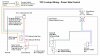
Sticking with the ground side controls, here's a wiring diagram the moves the vacuum switch into the main power line. It's a bit odd because the wire coming off the 4th Gear Pressure Switch simply exits the transmission case and goes to ground, but it should work fine, and doing it this way allows the indicator to work the same way it does in the previous diagram. You could in theory substitute a self-grounding switch here as well and only have two wires coming out of the transmission case, but I'm not sure at what pressures the various switches trigger at. Because of that, I would tend to use them in their original locations to be sure all was working as expected/desired.
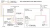
Taking things a step further, I created this diagram to move the control completely to the power side, switch to a one-wire self-grounding solenoid, and try to use the self-grounding switch in the "TCC Signal" location to control the indicator light. If this works, I think the indicator light would be more useful - assuming, of course, that my understanding of the "TCC Signal" switch is correct. If not, the previous diagram is probably the best so far. I have also included the required changes to have the vacuum switch control the power feed to the dash switch.
This is a small update on the previous diagram to add a "very high vacuum" switch to allow the TCC to stay locked whenever manifold vacuum is very high - such as when doing engine braking on a long downgrade. Other than a bit of shuffling on the diagram to make everything fit neatly, the only addition is the vacuum switch connected between the power side of the brake switch and the power feed to the SPDT Center-Off switch. This switch is hooked up to manifold vacuum (the other is hooked to ported vacuum) and can be tapped off the same vacuum line that goes to your vacuum gauge - you do have one of those, don't you? - so that you don't have to run more wires out into the engine compartment. If you decided to wire this new switch in the engine compartment, you would need a third wire heading out to the new vacuum switch and the two vacuum switches could share a common return wire back to the switch. This addition can easily be done after the above wiring has been done and tested.
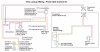
Finally, a bit of re-arranging and cleaning things up netted me this diagram. Before creating this, I roughed in the wiring on the vehicle and made this diagram follow the rough harness layout to make it easier to conceptualize what goes where while I was staring at the diagram and doing the actual wiring. On the actual harness I added connectors just inside of the firewall and just before the switch so the harness could be built in pieces outside the vehicle. If I had been able to size it better beforehand, these extra connectors would not have been needed, but they made my life easier and will come in handy if I ever have to remove or disconnect the wiring for service or troubleshooting.
Also, after playing with the wiring a bit on the vehicle while driving around, I could not get the indicator light to work the way I originally thought it should. To make the light work more sensibly, I added a ground wire to ground the indicator light and ran the "power" side of the light from the "lockup in any gear" lead coming off the switch. This lead is connected to the solenoid power lead inside the transmission, and gets power when the solenoid has power applied to it. That makes the indicator light go on whenever the solenoid should be locking up the converter. I'll have to research the pressure switch I was trying to use a bit more.
Here are the photos of the wiring work I did as I put things back together.
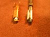
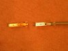
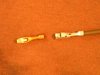
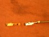
Wire Connectors
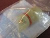
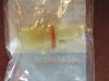
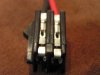
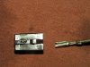
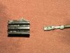
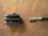
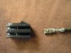
Here are close-up shots of the various wire connectors used on the TH700R4 transmission. The connectors on the pressure switches were standard fare - I had a box of crimp-on connectors already, so I just pulled the old wires out of the plastic connectors and put in new wires with new crimp-on connectors. I had a heck of a time finding the right connectors for the internal wiring plug, but I did manage to get a few that seem to work fine at my local GM dealer. He did have to scrounge through his wiring terminal kit to find them, though. The external wiring connector I got from the dealership has wiring pigtails attached and came with crimp-on butt connectors, but you can get the bare connector with terminals from PATC under part #71XXX. The case connector is still available from GM if needed, complete with a new o-ring. Check out my Automatic Overdrive Transmission Swap page for a complete list of all of the relevant parts, part numbers, and sources.
Attachments
-
 TH700R4InternalWiring01.jpg65.3 KB · Views: 88
 -
 TH700R4InternalWiring02.jpg70.4 KB · Views: 88
 -
 TH700R4InternalWiring03.jpg90.2 KB · Views: 88
 -
 TH700R4InternalWiring04.jpg72 KB · Views: 88
 -
 TH700R4InternalWiring05.jpg44 KB · Views: 88
 -
 TH700R4Pictures05.jpg60.6 KB · Views: 88
 -
 TH700R4InternalWiringDiagram01.jpg100.5 KB · Views: 88
 -
 TH700R4WiringDiagram01.jpg57.4 KB · Views: 88
 -
 TH700R4WiringDiagram02.jpg55.4 KB · Views: 88
 -
 TH700R4WiringDiagram03.jpg59.2 KB · Views: 88
 -
 TH700R4WiringDiagram04.jpg64.6 KB · Views: 88
 -
 TH700R4WiringDiagram05.jpg61.3 KB · Views: 88
 -
 TCI Wiring Diagram.JPG102.1 KB · Views: 88
 -
 TH700R4InternalWiring15.jpg67.4 KB · Views: 88
 -
 TH700R4InternalWiring14.jpg62.6 KB · Views: 88
 -
 TH700R4InternalWiring13.jpg85.4 KB · Views: 88
 -
 TH700R4InternalWiring12.jpg50.6 KB · Views: 88
 -
 TH700R4InternalWiring11.jpg45.3 KB · Views: 88
 -
 TH700R4InternalWiring10.jpg49.9 KB · Views: 88
 -
 TH700R4InternalWiring09.jpg98.8 KB · Views: 88
 -
 TH700R4InternalWiring08.jpg77.7 KB · Views: 88
 -
 TH700R4InternalWiring07.jpg86.7 KB · Views: 88
 -
 TH700R4InternalWiring06.jpg92.6 KB · Views: 88
 -
 TH700R4WiringConnectors17.jpg56.3 KB · Views: 88
 -
 TH700R4WiringConnectors16.jpg38.5 KB · Views: 88
 -
 TH700R4WiringConnectors15.jpg41.3 KB · Views: 88
 -
 TH700R4WiringConnectors14.jpg42.5 KB · Views: 88
 -
 TH700R4WiringConnectors13.jpg46.3 KB · Views: 88
 -
 TH700R4WiringConnectors12.jpg63.6 KB · Views: 88
 -
 TH700R4WiringConnectors11.jpg39.3 KB · Views: 88
 -
 TH700R4WiringConnectors10.jpg49.2 KB · Views: 88
 -
 TH700R4WiringConnectors09.jpg58.8 KB · Views: 88
 -
 TH700R4WiringConnectors08.jpg41.6 KB · Views: 88
 -
 TH700R4WiringConnectors07.jpg49.2 KB · Views: 88
 -
 TH700R4WiringConnectors06.jpg112 KB · Views: 88
 -
 TH700R4WiringConnectors05.jpg111.7 KB · Views: 88
 -
 TH700R4WiringConnectors04.jpg55.7 KB · Views: 88
 -
 TH700R4WiringConnectors03.jpg53.6 KB · Views: 88
 -
 TH700R4WiringConnectors02.jpg61.1 KB · Views: 88
 -
 TH700R4WiringConnectors01.jpg68.5 KB · Views: 88