Trans Cooler Install On Lincoln Navigator

If you can get a copper welding spoon to work as a heat sink to back up the pan you won’t burn through. Is the bung going to be inside the pan or outside?
 
keep in mind ,if your welding a drain bung, on the oil pan,
mounting the bung outside allows the oil , in the oil pan,
too fully drain if the bungs correctly located,
but if the bung is welded inside the oil pan,
the oil level in the pan up to the bung height won,t drain completely,
yeah the tapped amount might be small,
but a rapid full drain tends to flush out small metallic trash ,
that a raised internal bung traps and holds.
yeah use a magnetic oil drain plug and a decent size ring magnet on the oil filter
https://www.kjmagnetics.com/proddetail.asp?prod=RY0X04

http://garage.grumpysperformance.com/index.php?threads/magnets.120/#post-76605

http://garage.grumpysperformance.com/index.php?threads/inspecting-filter.4611/#post-12336

http://garage.grumpysperformance.co...h-the-oil-when-a-cam-failed.11542/#post-53330
 
Last edited:
it will be rather interesting to see how effective an obviously well designed fluid cooler unit is on that trucks trans fluid temps.
 
index.php


I see now but it is still close to the muffler. A barrier the length of the cooler and a little on each end would work as a shield for the air (hot) from the muffler and head pipe as that would give 2 air spaces between them and the cooler/fan housings.
 

Attachments

  • Untitled.jpg
    Untitled.jpg
    4.9 KB · Views: 4
Any suggestions for improvement ?

Is there a possible leak, can't find my modeling clay so I could build a dam and flood with
alcohol ?

Again, this is my setup with the head sink on the bottom side, which will be the inside of the
transmission oil pan.

FP06_DrainPlugPracticeWelding_01296.jpg

The arrow is where I stopped and then started again after re-positioning myself.

FP06_DrainPlugPracticeWelding_01298.jpg

After removing the heat sink from the bottom (seen below), this is what you see.

FP06_DrainPlugPracticeWelding_01300.jpg
.
 
it looks reasonably good RICK, I doubt youll have a leak,
it appears too be a very good weld job,looks to be a good bond,
yes you could go back around over the existing weld for a second pass,
and if your concerned.
you can also brush on a coating of J&B weld epoxy,
jbblock.jpg

over the weld bead,and paint the pan
,if you had a similar weld on the oil pan,
after the filler epoxy drys,this would appear too
blend and improve the weld bead appearance ,
and too smooth and fill any potential micro pin-holes.
thats one option, and thats why I generally prefer TIG welding ,
as you can go back around several times with TIG,
adding or not adding metal filler as required,
unlike MIG that always adds fill wire.
 
Last edited:
That looks really nice Rick. It does not look like it will leak from what i am seeing..
But then again....I blew my motor up, soooo. take it with a grain of salt.:p:)
 
I think you are fine. Your suspected leak is where you started and stopped. A tack weld may be an option if you will feel better.
 
Now I need to plan how I will wire the fans. Wondering how I can do that from a fuse panel without using a Fuse Tap. It will require accessing the back of the fuse panel, I've played with the latches some, but don't see exactly how to release the panel from it's mount.

Fuse Tap
https://www.youtube.com/results?search_query=fuse+tap

Any ideas how I can access the back of the fuse panel ???

FP01_FusePanel_01301.jpg

This photo shows 1/4 of the circumference of the fuse panel, it's replicated 3 more
times around the panel.

FP01_FusePanel_01303.jpg
.
 
personally I would run a separate fused relay, if theres no way to easily access a fuse circuit in the existing fuse box easily
https://www.the12volt.com/relays/relaydiagrams.asp (read)

https://www.amazon.com/Blue-Sea-Sys...coding=UTF8&psc=1&refRID=FHJ1VKPV03Y412399768

powerbarout.jpg


85 and 87a -> Ground

86 -> Power

30 -> Output

-30 = constant [positive (+)] power (usually wired directly to car battery)
-85 = coil ground (wired to the negative (-) battery terminal or any grounded metal panel in the car)
-86 = coil power (wired to the control source. could be a switch, or it could be the car's IGN or ACC circuit.)
-87 = switched [positive (+)] power output. (when the relay coil is powered, lead/pin 87 is connected to lead/pin 30)
-87a = [on 5 lead/pin relays only] this lead/pin is connected to lead/pin 30 when the coil is NOT powered.
 
Where did you grab a switched power source?

wiper motor might be a good source. Could pull the hot pin from the plug and solder in a wire on the new pin that will hold the two wires, then push it back into the plug... Simular to a relay wiring.
 
https://www.amazon.com/VIOFO-Circui...ocphy=9012039&hvtargid=pla-586493323860&psc=1


as mentioned you could use a fuse power tap,, but..
Ive generally just found an electrical power,
source for a switched power with a multi meter,
or tapped off the battery terminal and added a manual switch...
depends on what I was trying to accomplish,
Ive generally run 10 ga wire to a relay is any significant amp loads were anticipated,
and soldered in a relay and fuse as required.
btw one guy I know wired a power fan relay, for his transmission fluid cooler into the brake light circuit,
to activate the relay and had electrical power for the fan,
direct from the battery to power the fan,
as he stated, if I,m sitting at a stop light,
I won,t have air rushing over the trans fluid cooler,
so the fan needs to be on, if I'm moving the movement of the car should provide air flow,
and yeah he installed a trans fluid temp gauge and a manual over-ride switch,
with a second relay, that resets the circuit too off if the ignition keys turned off,
so the fan can not be left running with the car parked,
if the manual switch is flipped to the on position last time the engine was on.
to activate the trans fluid cooler fan.
(no I don,t have a diagram but it certainly can,t be hard to wire ,
this guy did it and hes certainly not an electrical expert by any stretch.)
great lets us know what you find out

btw,is that trans fluid cooler is mounted like this , on the return line from the radiator correct "
cooler+diagram.jpg

https://www.the12volt.com/relays/relaydiagrams.asp (read)


https://www.summitracing.com/parts/...MI-rP_gp6F5AIVyAOGCh3PWAB_EAQYASABEgKCevD_BwE

https://www.amazon.com/PACK-AMP-Wat...DJGHS4MHT2D&psc=1&refRID=SDXCB01E5DJGHS4MHT2D

https://www.amazon.com/Ehdis-Truck-...=B01KFKEHMG&psc=1&refRID=SDXCB01E5DJGHS4MHT2D
61VLK.jpg

Ehdis [2 Pack Car Truck Motor Heavy Duty Heavy Duty 5-Pin 80A 12V On/Off Normally Open SPDT Relay Socket Plug 5 Wire Automotive


Price: $12.99


Last edited:
Went from planning to doing on this project. I have more photos, but I thought this was worth
doing tonight. The trans is a ZF 6HP26 that's sold by ZF in Europe, that Ford and Lincoln are
using for their 6 speed automatic trans. I have the factory maintenance book and it wants a fluid
and filter change at 60,000 miles. The problem is there are NO Dipstick, it checked at a certain
temp, then you pull the plug on the side of trans to see if any fluid runs out. It's just like checking
a rear end fluid.

I'm going to do more than just refill the pan, I'm going to do a complete fluid change of approximately
12 quarts. More on that later. Anyway this is the fluid I drained today with 89,488 miles. So much
for a lifetime fluid that so many manufacture proclaim.

FP07_TransFluid_88488_Miles_01327.jpg
 
thats impressive, and considering many people never change trans fluid,
its something too think about seriously
 
First thing I did was level the Navigator when I put it on the safety stands .....front to back and
side to side. This will help when it comes time to set the fluid level.

FP08_NavigatorOnJackStands_01331.jpg
FP08_LevelNavigator_01305.jpg
FP08_LevelNavigator_01306.jpg

That BIG blue tote under the Navigator was a big help keeping the mess to a minimum. It cover
the trans, front to back and side to side while the pan was being removed and fluid was coming
from everywhere.

Before pulling the pan I marked places for the temp sensor and drain plug. I even thought about
an alternate sensor location just encase the first one didn't work out. Days before I identified the
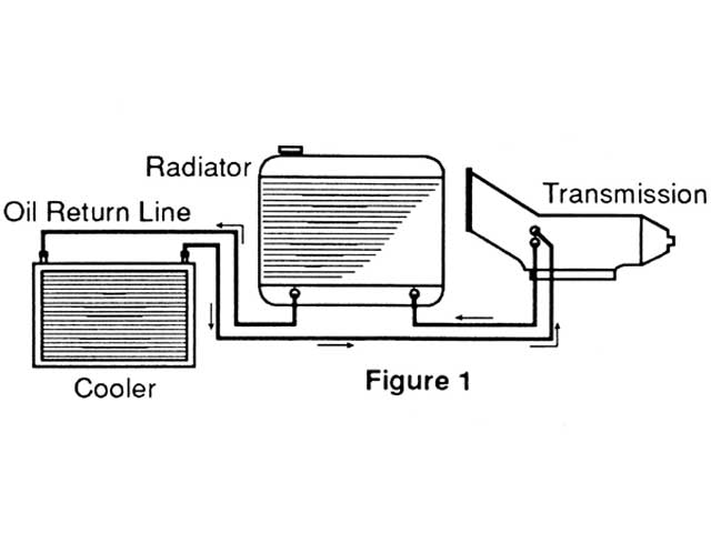
the OEM cooler return line so I would know where to make my cuts. BTW, the Navigator has a
separate cooler for the transmission, it does not go thru the radiator. On the downside, there are
3 heat exchangers in the front. They line up like this ........ trans cooler, A/C condenser and then
the radiator, starting at the front.

FP08_TempSensorLocation_01307.jpg

First thing after I got the pan on the bench was to check for debris/clutch material in the
bottom. I wiped the pan in the middle and got almost nothing.

FP08_InsidePanBeforeCleaning_01317.jpg

Next was the two magnets, there was definitely more junk there.

FP08_PanMagnetsBeforeCleaning_01319.jpg

Drilling the pan trying to make sure the surrounding surface was flat. Trying to do this
on the curve is much harder. I bent the pan rails down trying to get access to weld all
the way around.

FP08_TempSensorBeforeWelding_01324.jpg

OK ...... Quit staring at the hole below!!!
YES I blew a hole in the pan, but what the HELL is a welder for if you can't fix a mistake. :eek:

FP08_TempSensorWelded_01325.jpg

Finally I wanted to document the info below, before I painted the pan. I did use some masking
tape to cover it during the painting. When I check the fluid level the engine has to be running
and the fluid temp as shown below.

FP08_6HP26_Fluid-LevelInfo_01330.jpg

This is for ORF, yes I did wet sand the pan.

FP08_PanPreppedBeforePainting_01332.jpg
.
 
impressive quality job RICK,
(AS USUAL)
and damn good pictures and explanation:D
 
Back
Top