if your ignition is working correctly your getting a hot blue spark, thats got a noticeable audible snap to it if you test an ignition wire by removing it from a plug temporarily and holding it about a 1/3" from a ground like the block,a quick check of your shop manual for the correct advance and procedures for setting the timing and your timing light will be very useful in setting the ignition timing.
if you don,t have that snappy blue spark,, but only a dull yellow or red spark, chances are decent that the coil or the battery voltage or possibly a ground strap are defective, so check those possibilities , and don,t forget youll need both a timing light and a v.o.m. meter to check out your ignition.
WATCH THE VIDEO
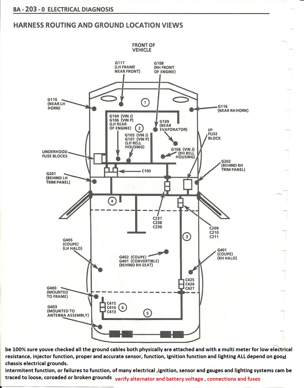
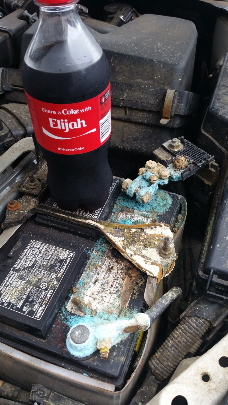
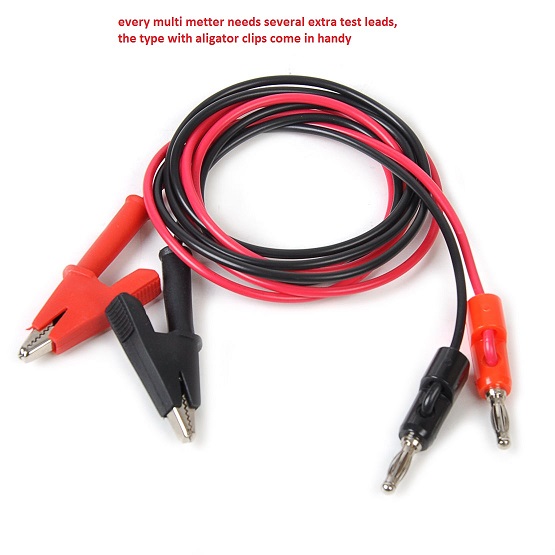
If your chasing an intermittent, engine miss or stumble, youll need to logically isolate and test each potential source, and while it might be related to fuel pressure, carburetor float levels or crud in the carburetor fuel bowls, or a vacuum leak, on a hose or the brake booster, or fuel pressure or volume of fuel delivery or the carb fuel level, you might also be dealing with a loose electrical connection , on the battery , other wiring or system ground in the cars ignition system or sensors, or something simple like water in the fuel, or a clogged fuel filter, the point here is LOGICALLY ISOLATE AND TEST THE POTENTIAL OPTIONS, AND IT HELPS TO HAVE A FACTORY SHOP MANUAL< A MULTI METER A VACUUM GAUGE AND TAKING NOTES WON,T HURT EITHER
DON,T SKIP READING THE LINKS AND SUB LINKED INFO
AND IF AQ LINKS STATES...CLICK TO EXPAND...CLICK THE LINK AND READ IT!
http://garage.grumpysperformance.co...ei-distributors-ignition-advance-curve.16425/
http://www.4secondsflat.com/HEI_Distributors.html
viewtopic.php?f=36&t=10946&start=16
https://www.customwiresets.com/product.php?productid=16162&cat=0&page=1&featured
http://easyautodiagnostics.com/gm/4.3L-5.0L-5.7L/distributor-mounted-icm-tests-1
http://garage.grumpysperformance.co...-auto-elecrtrical-connectors.3105/#post-68805
https://www.speedwaymotors.com/Speedway-Motors-Pontiac-V8-Pro-Series-Distributor,443619.html
very good
https://www.google.com/search?q=art...me..69i57.240303j0j4&sourceid=chrome&ie=UTF-8
good
Arctic Silver 5 High-Density Polysynthetic Silver Thermal Compound AS5-12G - OEM
good
https://www.amazon.com/dp/B019BZENY...tWxSNqn1YeeooBP4D.BQ&slotNum=18&tag=wepcus-20
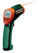
Ive found its a whole lot faster to use a quality IR temp gun, to locate a individual cylinder that's mis-firing as it tends to run significantly cooler than adjacent cylinders, or hotter if its a vacuum leak at times, as lean F/A mixes tend to run hotter
(Ive used this one for years)
http://www.professionalequipment.com/ex ... ermometer/
Wide temperature range from -58 to 1832°F (-50 to 1000°C)
many temp guns don,t read high enough or accurately enough
http://www.professionalequipment.com/ex ... ermometer/
that you can use on the engine to check ALL 8 exhaust temps, individually, this quickly locates plugged injectors or vacuum leaks ETC
Wide temperature range from -58 to 1832°F
when selecting an IR gun for automotive use, you really want to be able to read from 0 F deg-about 1400F deg. to cover most conditions you'll test for
http://easyautodiagnostics.com/gm/4.3L- ... cm-tests-3
below youll find some helpful links
http://www.megamanual.com/ms2/GM_7pinHEI.htm
http://rmcavoy.freeshell.org/HEI.html
http://garage.grumpysperformance.co...ation-and-bits-of-distributor-i-d-info.14880/
http://www.performancedistributors.com/faqs.htm
http://www.chevelles.com/techref/ftecref5.html
viewtopic.php?f=50&t=3110&p=8302#p8302
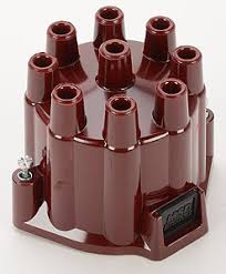
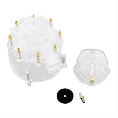
summit racing and a few other places sell clear distributor caps which can be useful
http://www.summitracing.com/parts/sum-g5236
http://documents.msdperformance.com/5520.pdf
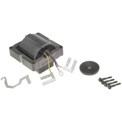
The ignition control module in the distributor is another item that normally fails when hot, that needs to be replaced is you suspect its defective
https://www.competitionproducts.com...ail&utm_term=0_dccdcdc641-e5856f3f6b-34475433
I have yet too try it personally yet, but this modual above SHOULD BE a noticeable improvement

http://www.crankshaftcoalition.com/wiki ... istributor
http://static.summitracing.com/global/i ... m30247.pdf
http://www.summitracing.com/parts/msd-8 ... structions
http://prestoliteweb.com/Portals/0/down ... e_0006.pdf
http://www.chevelles.com/techref/ftecref5.html
http://www.kendrick-auto.com/ignition.htm
http://www.pontiacstreetperformance.com ... curve.html
http://www.73-87.com/7387garage/drivetrain/hei.htm
http://rmcavoy.freeshell.org/HEI.html
http://www.enginebuildermag.com/2009/07/properly-matching-your-camshaft-and-distributor-gear/
http://www.pontiacstreetperformance.com ... curve.html
http://www.corvette-restoration.com/res ... v_Spec.pdf
http://www.chevelles.com/techref/ftecref5.html
http://www.circletrack.com/howto/1842_i ... index.html
http://www.chevelles.com/techref/ftecref5.html
http://www.superchevy.com/how-to/97438/ ... m#cxrecs_s
http://www.hotrod.com/techarticles/sett ... index.html
http://www.chevyhiperformance.com/howto ... index.html
viewtopic.php?f=70&t=251&p=6437&hilit=+shiming#p6437
http://www.ehow.com/how-does_4809570_tr ... butor.html
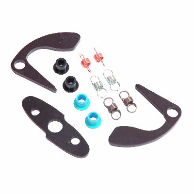
be sure you inspect the distributor gear for excessive wear
especially if you changed from a flat tappet to a roller cam.
http://www.summitracing.com/parts/CCA-12200/
http://www.summitracing.com/parts/CCA-12140/
viewtopic.php?f=70&t=251
videos
http://streetmuscleaction.com/engines/hei/
http://www.73-87.com/7387garage/drivetrain/hei.htm
http://www.enginefactory.com/high_perfo ... ibutor.htm
http://www.summitracing.com/parts/MRG-6011/?rtype=10
http://cranecams.com/pdf/90001700c.pdf
http://www.customclassictrucks.com/howt ... index.html
http://corp.advanceautoparts.com/englis ... 1001he.asp
http://reviews.ebay.com/HEI-Ignitions-A ... 0002053885
http://www.ehow.com/how_5453767_rebuild ... butor.html
http://www.circletrack.com/techarticles ... index.html
http://www.davessmallbodyheis.com/
http://temp.corvetteforum.net/c3/joevet ... urve.shtml
http://arrc.epnet.com/autoapp/9110/9110 ... System.htm
http://www.rodandcustommagazine.com/tec ... index.html
http://www.hotrod.com/techarticles/sett ... index.html
viewtopic.php?f=36&t=1169&hilit=+alternator
viewtopic.php?f=70&t=840&p=1696&hilit=taylor#p1696
if you don,t have that snappy blue spark,, but only a dull yellow or red spark, chances are decent that the coil or the battery voltage or possibly a ground strap are defective, so check those possibilities , and don,t forget youll need both a timing light and a v.o.m. meter to check out your ignition.
WATCH THE VIDEO
If your chasing an intermittent, engine miss or stumble, youll need to logically isolate and test each potential source, and while it might be related to fuel pressure, carburetor float levels or crud in the carburetor fuel bowls, or a vacuum leak, on a hose or the brake booster, or fuel pressure or volume of fuel delivery or the carb fuel level, you might also be dealing with a loose electrical connection , on the battery , other wiring or system ground in the cars ignition system or sensors, or something simple like water in the fuel, or a clogged fuel filter, the point here is LOGICALLY ISOLATE AND TEST THE POTENTIAL OPTIONS, AND IT HELPS TO HAVE A FACTORY SHOP MANUAL< A MULTI METER A VACUUM GAUGE AND TAKING NOTES WON,T HURT EITHER
DON,T SKIP READING THE LINKS AND SUB LINKED INFO
AND IF AQ LINKS STATES...CLICK TO EXPAND...CLICK THE LINK AND READ IT!
http://garage.grumpysperformance.co...ei-distributors-ignition-advance-curve.16425/
Relay/s, Voltage Drop/s, Current Flow, Grounds and ... more
A relay is nothing more than a device that uses a low-current signal to operate a high-current circuit, he solenoid on your starter is a type of relay that uses the low-current signal from your starter switch to operate the high-current circuit between the battery and the starter motor...
garage.grumpysperformance.com
viewtopic.php?f=36&t=10946&start=16
https://www.customwiresets.com/product.php?productid=16162&cat=0&page=1&featured
http://easyautodiagnostics.com/gm/4.3L-5.0L-5.7L/distributor-mounted-icm-tests-1
http://garage.grumpysperformance.co...-auto-elecrtrical-connectors.3105/#post-68805
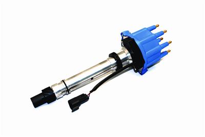
https://www.speedwaymotors.com/Speedway-Motors-Pontiac-V8-Pro-Series-Distributor,443619.html
on-ehow said:Testing the GM HEI Distributor
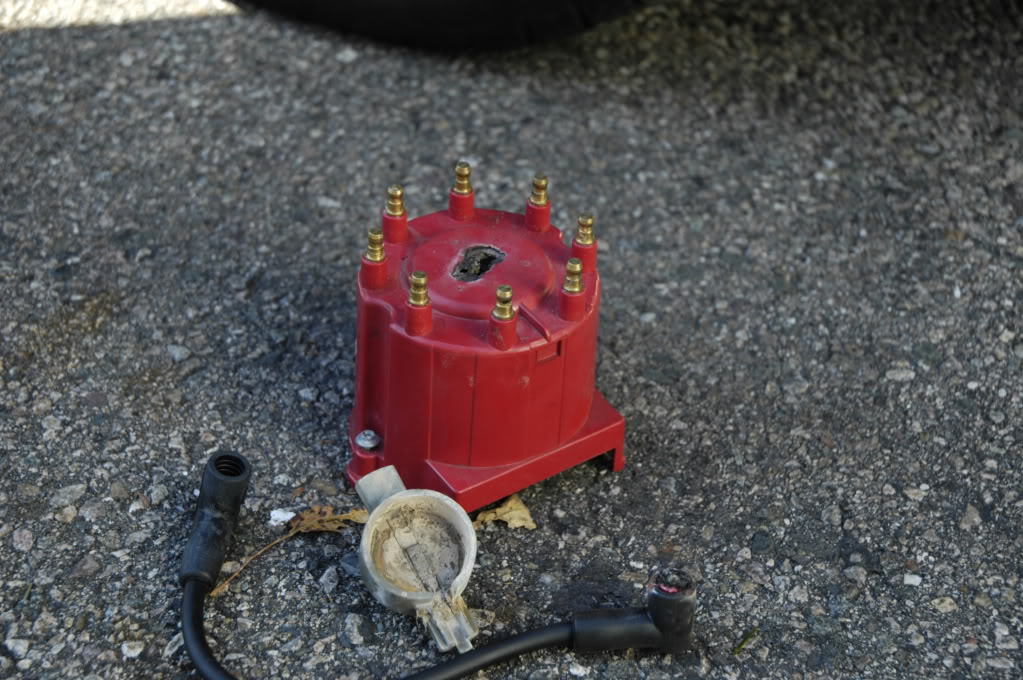
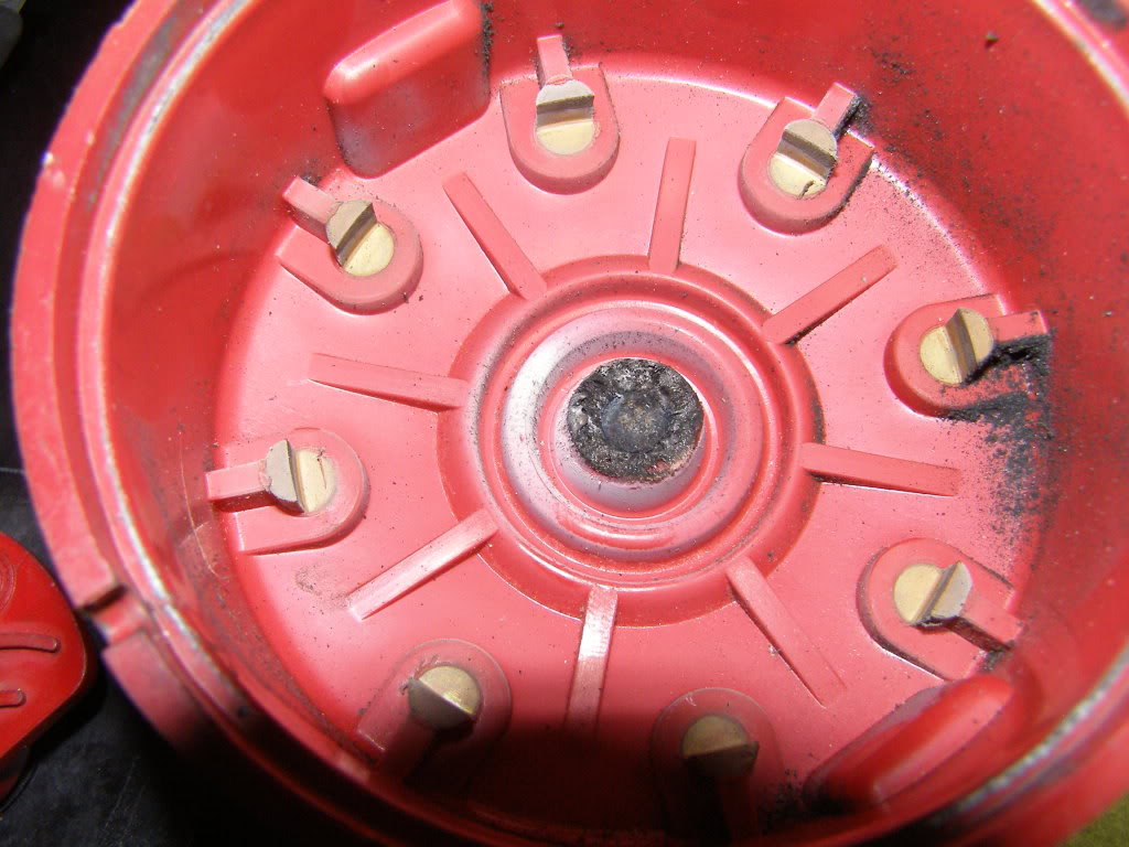
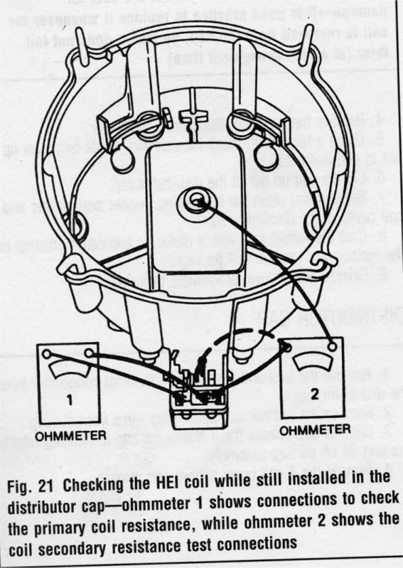
A no-spark condition is checked by checking the distributor for power at the connector on the side of the cap. If there is power, disconnect the electrical connector and remove the cap. Check the rotor and the cap for excessive wear. Check the coil tower for excessive wear. Remove the top plastic cap on the distributor cap. Use an ohmmeter and check the coil positive terminal to the metal case of the coil. The reading should be infinity. Check the coil tower and the negative terminal. The reading should be 900 ohms. Check the positive terminal to the negative terminal. The reading should be around 700 ohms. If any of these tests show drastically different readings, the coil is bad. If the coil is good, the cap and rotor are not cracked or worn significantly and there is no spark at any wire, replace the ignition module.
keep in mind this whole web site is designed to help you learn and solve problem, and ideally add to the web sites, knowledge base ,
so others can learn from your successfully solving issues and posting your experiences
http://garage.grumpysperformance.co...cting-a-distributor-for-your-application.855/
https://www.chevelles.com/threads/ignition-101.189195/
http://easyautodiagnostics.com/gm/4.3L-5.0L-5.7L/distributor-mounted-icm-tests-1
http://garage.grumpysperformance.co...e-hazy-light-under-the-hood.12017/#post-57463
http://easyautodiagnostics.com/gm_icm_d ... dule_1.php
Instructions
1
Verify voltage at the distributor. On the side of the distributor is a plug-in receptacle that will have a heavy-gauge, red wire attached to it. The large gauge is necessary to produce the high voltage demands of the spark plugs. Probe this wire with a properly grounded test light while the ignition key is turned on. The light should brightly glow. If there is no voltage, the ignition switch or related wiring is defective.
2
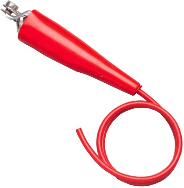
Detach a spark plug wire from a spark plug and replace the plug with a spark plug tester. The spark plug tester (available at most auto parts stores) will have an alligator clip attachment. Clip this to engine metal--not plastic--and have an assistant crank the engine. Carefully observe the tester and see if there is a spark that flashes in cycle with the engine as it cranks over. If there is no spark and there is 12 volts going to the distributor, test for engine or distributor failure.
3
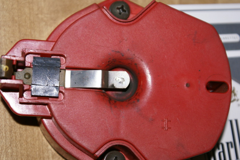
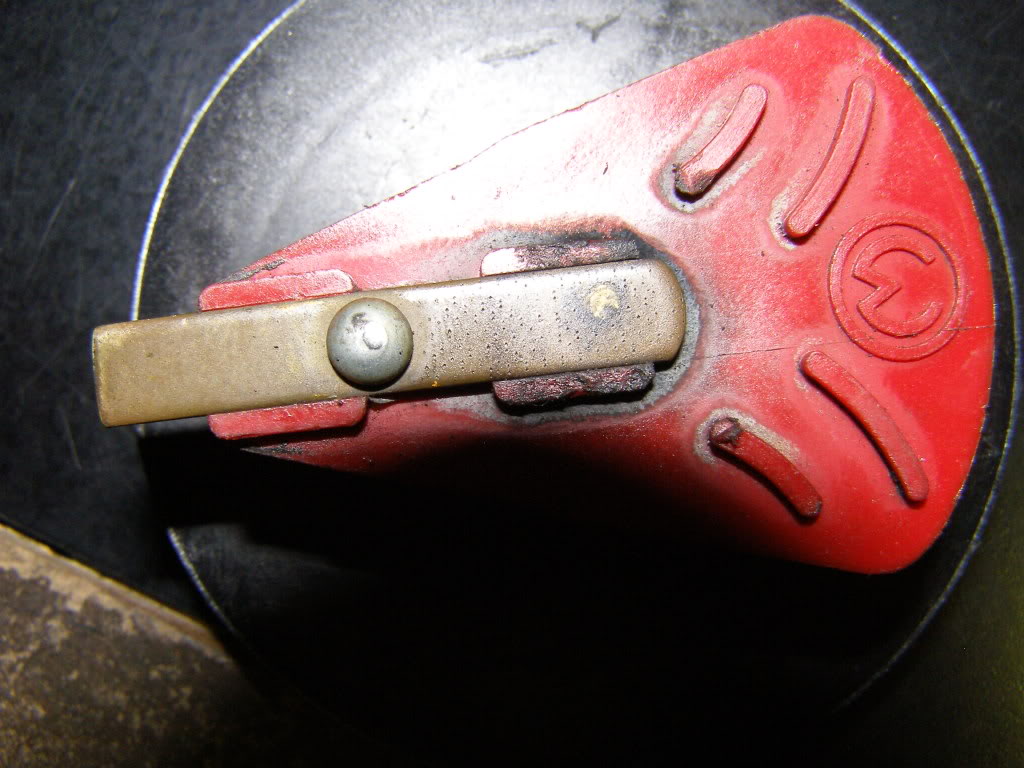
Remove the distributor cap and inspect the rotor assembly while an assistant cranks the engine. If the rotor does not move, there is internal mechanical failure of the engine or distributor. If the rotor moves, there is electronic circuit failure in the distributor that will need to be repaired.
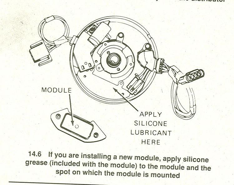
use one of the thermal grease under the ignition module,CARCRAFT said:Easy tests for HEI system:
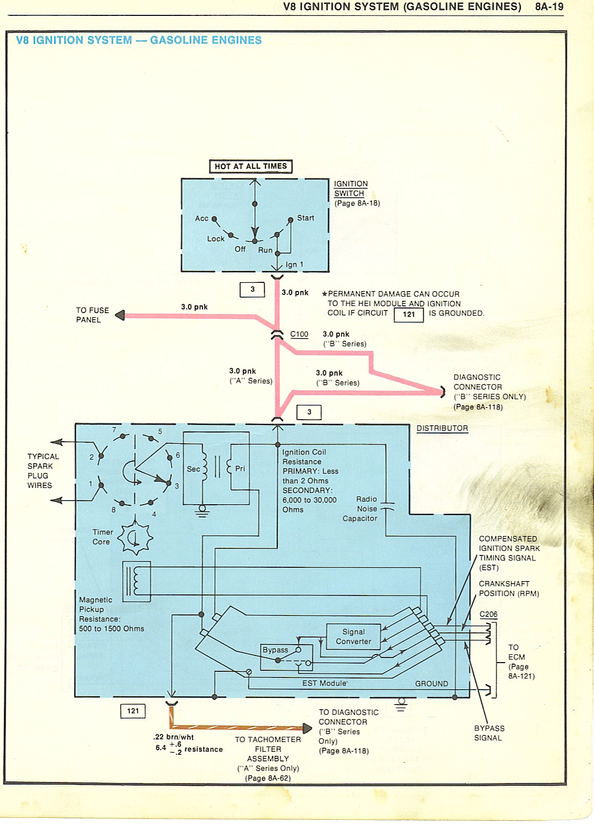
1. Test for power at the pink BAT terminal. You should have battery voltage w/ the key in the start and RUN positions.
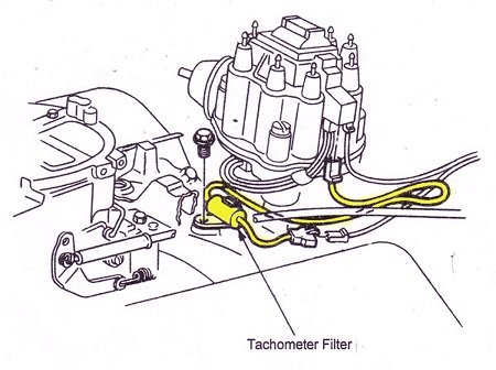
2. Connect the ground side of your test lamp to the battery POSITIVE cable. Probe the TACH terminal on the dist. cap while a helper attempts to start the engine. The test lamp should blink repeatedly as the engine cranks. No blink= bad module or pickup coil. Further testing is required to pinpoint the problem. Blink but no spark = bad ignition coil.
3. Remove the cap & rotor. Remove the green & white leads from the module. Connect your ohmmeter to the green & white leads. You should have approx. 800-1500 ohms depending on the ambient temperature. Open circuit (infinite ohms) = bad pickup coil.
Wiggle the green & white leads as you test. Ohm reading should remain constant if the leads are good. If the reading varies as the leads are wiggled, the pickup coil is bad. You'll often find broken pickup coil leads this way.
4. DVOM (meter) still connected to green & white leads. Set your DVOM to AC VOLTS. Have a helper crank the engine as you watch the AC VOLTS reading. A good pickup coil will produce about 3V AC when cranking. Less than approx. 2V AC indicates a bad pickup coil.
let me take you a little farther...
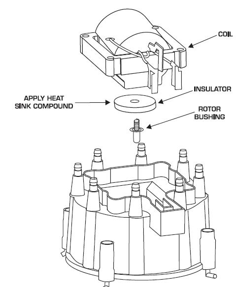
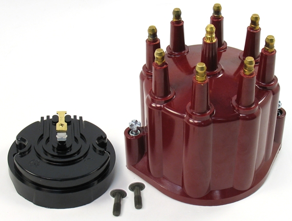
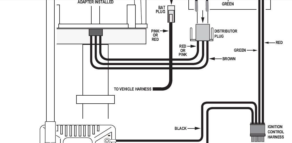
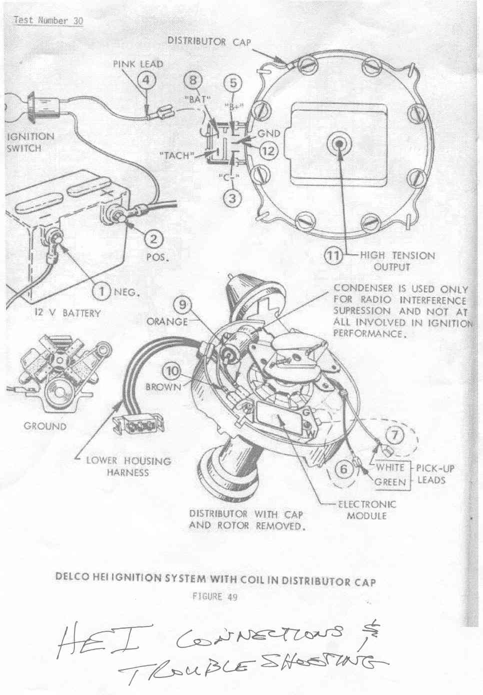
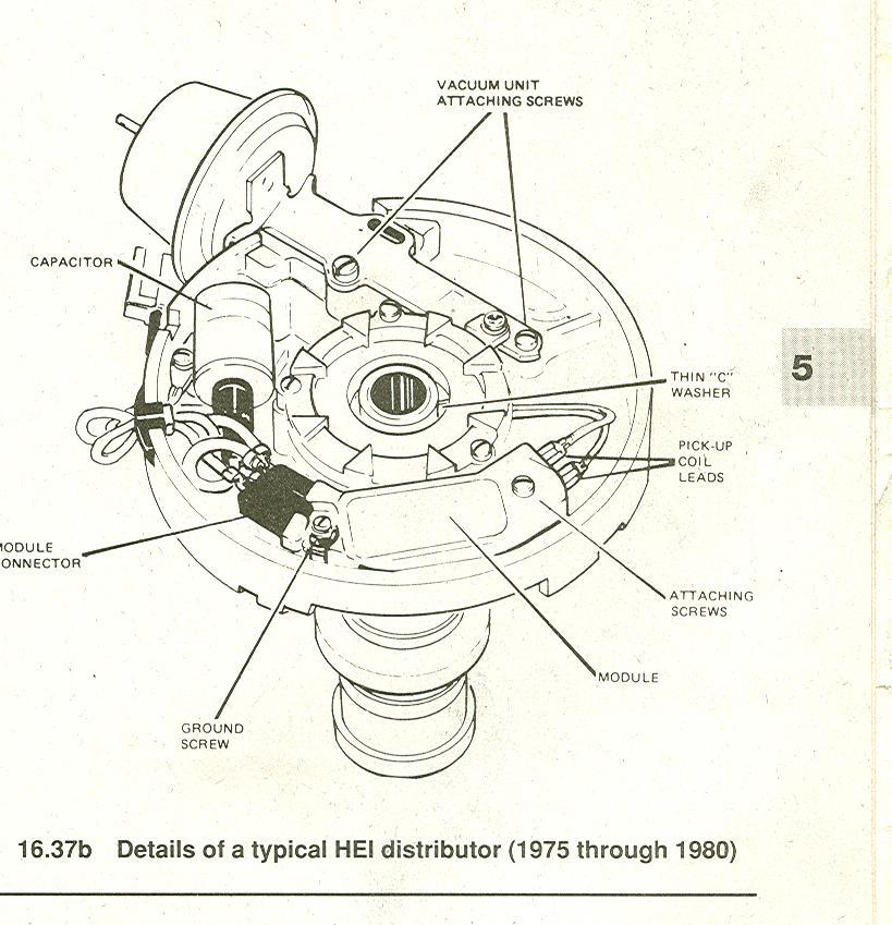
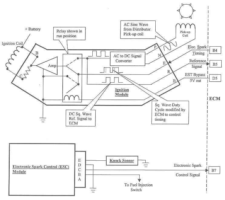
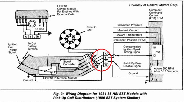
when you turn the key on.. positive power is sent through the red wire plugged into the BAT side of the HEI cap.. inside the cap you will notice the coil wires have a T shaped terminal.... the red wire goes into the coil.. but it also connects to the right side of the 3 wire harness from the cap to the housing from there to the B+ terminal on the module...
the TACH terminal in the cap.. also has a T terminal.. it also connects to the LEFT side of the 3 wire harness down to the housing and connects to the C connector on the module...
wait.. there is a third wire in the three wire harness... this is where a LOT of problems crop up...
this is the ground strap... it goes into the cap before the coil does.. fits into the middle connection of the 3 wire harness..
the screw that goes through the coil laminations directly over the hooked end needs to have the black wire from the coil..
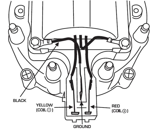
why.... this is the ground for the coil... without it .. the voltage can build up in the frame of the coil till it flashes over like a lightening bolt.. and can be as loud as a shot gun blast going off under your hood..
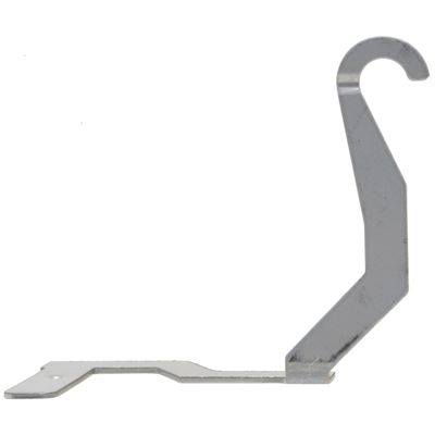
the center wire goes down and is connected to the condenser hold down strap and the strain relief hold down..
this is really important.. the spark has to make it back up this wire and to the coil after it passes through the spark plugs..
back to the description...
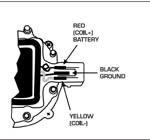
there are 2 screw that hold this coil cover down.. you will notice the TACH and the BAT markings on it..
test with your test light clip hooked to ground to the BAT side.(red coil wire)... you should get voltage...
test with your test light clip hooked to POSITIVE.. the TACH side.(white or yellow coil wire) .. while somebody cranks the engine...
the test light should flash.. this is because the module is making and breaking ground to the C connection inside the distributer. ....... this should make your test light flash..
i normally just remove the module and take it to the parts store as some of them have module testers... where they plug them in and an automated test is run...
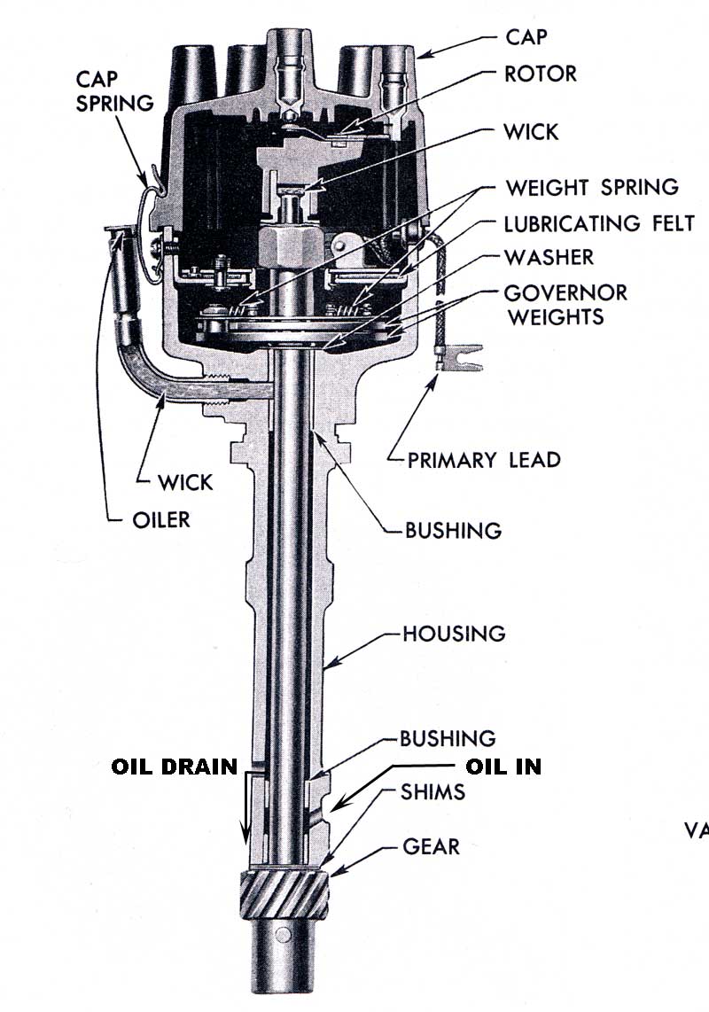
i should probably continue on my HEI description...
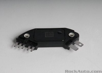
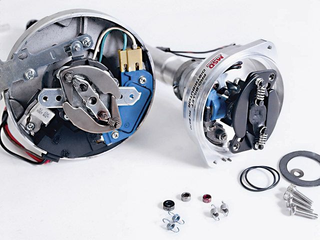
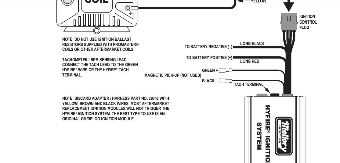
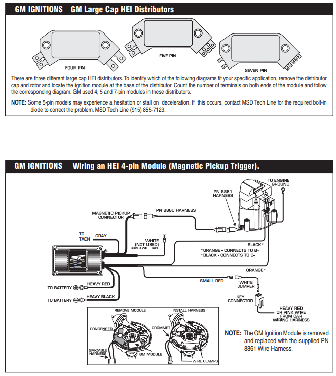
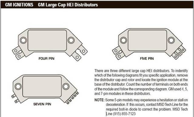
the 4 pin GM HEI module..
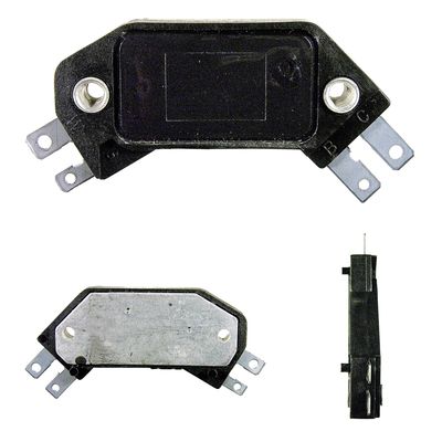


you can see the pins on the right side of this module..
B is the switched ignition power..
c goes up to the Tach and to the yellow or white wire on the coil.
wait.. where is the ground connection.. see the 2 hold down screws... the rivets going through the plastic when the screws go through them ground the module...
why is the ground important.. .. the module connects the C terminal to ground and then breaks that connection to discharge the ignition coil...
on the left end of this 4 pin module are the terminals that go to the pick up coil...
the pick up coil creates a small AC voltage.. usually just about 1 volt AC.. when the AC voltage comes to 0.3 volts positive. the power transistor in the module turns on and grounds the coil.. allowing the electrons to flow into the coil primary creating a magnetic field..
this AC voltage is created by the reluctor spinning above the pick up coil...
this is the second time i have typed this out tonight.. hmm...
when the tips of the reluctor line up with the pick up coil tips.. the voltage will drop back to zero. at this point the power transistor opens .. breaking the connection to ground.. this causes the magnetic field in the coil primary to collapse through the secondary windings and create a high voltage spark....
as the reluctor tips move away from the pick up coil tips.. the voltage continues its negative swing. then it starts rising again as it approaches the tips again..
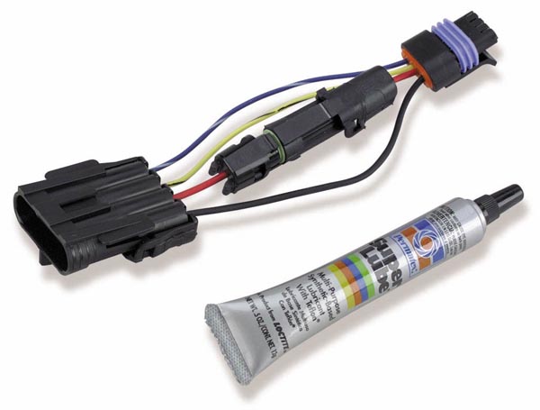
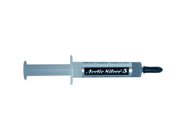
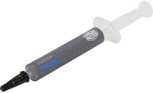
one of the most important things you can remember.. there has to be dielectric tune up grease is not as good as thermal grease
under the module or it will die... if it starts again once it cools off does not matter .. once thermally damaged.. its toast.. it will fail eventually.. leaving you stranded... usually at the worst point..

very good
https://www.google.com/search?q=art...me..69i57.240303j0j4&sourceid=chrome&ie=UTF-8
good
Arctic Silver 5 High-Density Polysynthetic Silver Thermal Compound AS5-12G - OEM
good
https://www.amazon.com/dp/B019BZENY...tWxSNqn1YeeooBP4D.BQ&slotNum=18&tag=wepcus-20
Ive found its a whole lot faster to use a quality IR temp gun, to locate a individual cylinder that's mis-firing as it tends to run significantly cooler than adjacent cylinders, or hotter if its a vacuum leak at times, as lean F/A mixes tend to run hotter
(Ive used this one for years)
http://www.professionalequipment.com/ex ... ermometer/
Wide temperature range from -58 to 1832°F (-50 to 1000°C)
many temp guns don,t read high enough or accurately enough
http://www.professionalequipment.com/ex ... ermometer/
that you can use on the engine to check ALL 8 exhaust temps, individually, this quickly locates plugged injectors or vacuum leaks ETC
Wide temperature range from -58 to 1832°F
when selecting an IR gun for automotive use, you really want to be able to read from 0 F deg-about 1400F deg. to cover most conditions you'll test for
http://easyautodiagnostics.com/gm/4.3L- ... cm-tests-3
below youll find some helpful links
http://www.megamanual.com/ms2/GM_7pinHEI.htm
http://rmcavoy.freeshell.org/HEI.html
http://garage.grumpysperformance.co...ation-and-bits-of-distributor-i-d-info.14880/
http://www.performancedistributors.com/faqs.htm
http://www.chevelles.com/techref/ftecref5.html
viewtopic.php?f=50&t=3110&p=8302#p8302
summit racing and a few other places sell clear distributor caps which can be useful
http://www.summitracing.com/parts/sum-g5236
http://documents.msdperformance.com/5520.pdf
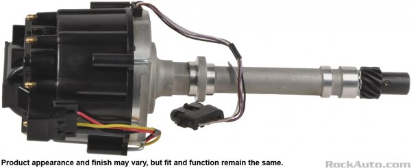
The ignition control module in the distributor is another item that normally fails when hot, that needs to be replaced is you suspect its defective
https://www.competitionproducts.com...ail&utm_term=0_dccdcdc641-e5856f3f6b-34475433
I have yet too try it personally yet, but this modual above SHOULD BE a noticeable improvement
http://www.crankshaftcoalition.com/wiki ... istributor
http://static.summitracing.com/global/i ... m30247.pdf
http://www.summitracing.com/parts/msd-8 ... structions
http://prestoliteweb.com/Portals/0/down ... e_0006.pdf
http://www.chevelles.com/techref/ftecref5.html
http://www.kendrick-auto.com/ignition.htm
http://www.pontiacstreetperformance.com ... curve.html
http://www.73-87.com/7387garage/drivetrain/hei.htm
http://rmcavoy.freeshell.org/HEI.html
http://www.enginebuildermag.com/2009/07/properly-matching-your-camshaft-and-distributor-gear/
http://www.pontiacstreetperformance.com ... curve.html
http://www.corvette-restoration.com/res ... v_Spec.pdf
http://www.chevelles.com/techref/ftecref5.html
http://www.circletrack.com/howto/1842_i ... index.html
http://www.chevelles.com/techref/ftecref5.html
http://www.superchevy.com/how-to/97438/ ... m#cxrecs_s
http://www.hotrod.com/techarticles/sett ... index.html
http://www.chevyhiperformance.com/howto ... index.html
viewtopic.php?f=70&t=251&p=6437&hilit=+shiming#p6437
http://www.ehow.com/how-does_4809570_tr ... butor.html
be sure you inspect the distributor gear for excessive wear
especially if you changed from a flat tappet to a roller cam.
http://www.summitracing.com/parts/CCA-12200/
http://www.summitracing.com/parts/CCA-12140/
viewtopic.php?f=70&t=251
videos
http://streetmuscleaction.com/engines/hei/
http://www.73-87.com/7387garage/drivetrain/hei.htm
http://www.enginefactory.com/high_perfo ... ibutor.htm
http://www.summitracing.com/parts/MRG-6011/?rtype=10
http://cranecams.com/pdf/90001700c.pdf
http://www.customclassictrucks.com/howt ... index.html
http://corp.advanceautoparts.com/englis ... 1001he.asp
http://reviews.ebay.com/HEI-Ignitions-A ... 0002053885
http://www.ehow.com/how_5453767_rebuild ... butor.html
http://www.circletrack.com/techarticles ... index.html
http://www.davessmallbodyheis.com/
http://temp.corvetteforum.net/c3/joevet ... urve.shtml
http://arrc.epnet.com/autoapp/9110/9110 ... System.htm
http://www.rodandcustommagazine.com/tec ... index.html
http://www.hotrod.com/techarticles/sett ... index.html
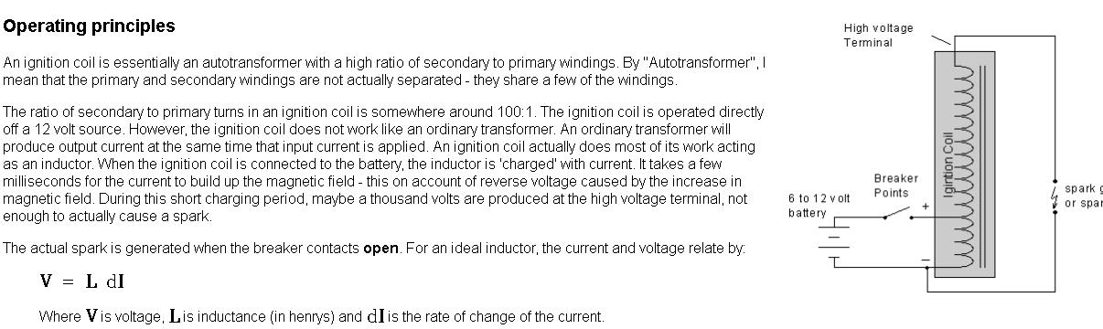
testing an ignition coil
"A SIMPLE QUICK CHECK FOR YOUR COIL IS :CHECK YOUVE GOT 12 VOLTS, AT THE COIL, PUT A TEST LIGHT TO GROUND AND THE NEG SIDE OF COIL AND CRANK ENGINE THE TEST LIGHT SHOULD FLASH OR FLICKER.(ANALOG METERS WITH A SWINGING NEEDLE,SWEEP ARE BETTER THAN DIGITAL) THIS WILL TELL IF YOUR TRIGGER IS...
garage.grumpysperformance.com
viewtopic.php?f=36&t=1169&hilit=+alternator
viewtopic.php?f=70&t=840&p=1696&hilit=taylor#p1696
Last edited by a moderator: