Troubleshooting bearing failure

cb9501

Member
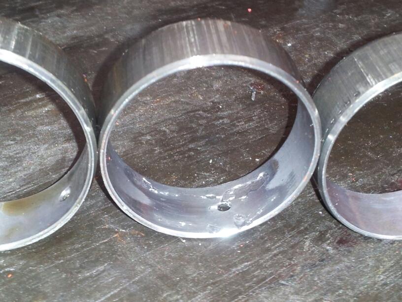
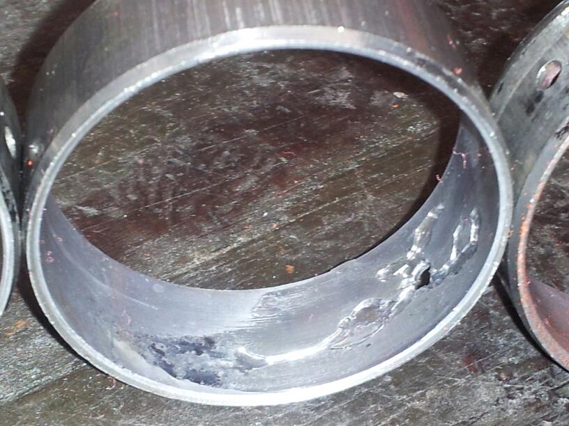
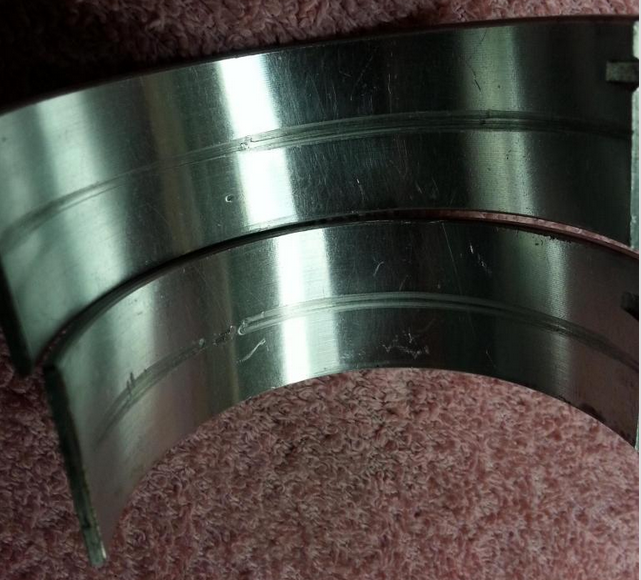
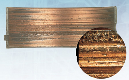
My motor has destroyed rod/main bearings in the first hour of driving it twice. I never took it above 4200rpm, and the oil was at 40 at idle, up to 50psi at 2500rpm and above. Pressure got worse as bearings wore out. I have it apart now, and it seems to get progressively worse from front to back, with the 2 furthest rear bearings, and associated rod bearings very worn. Cam seems fine though.

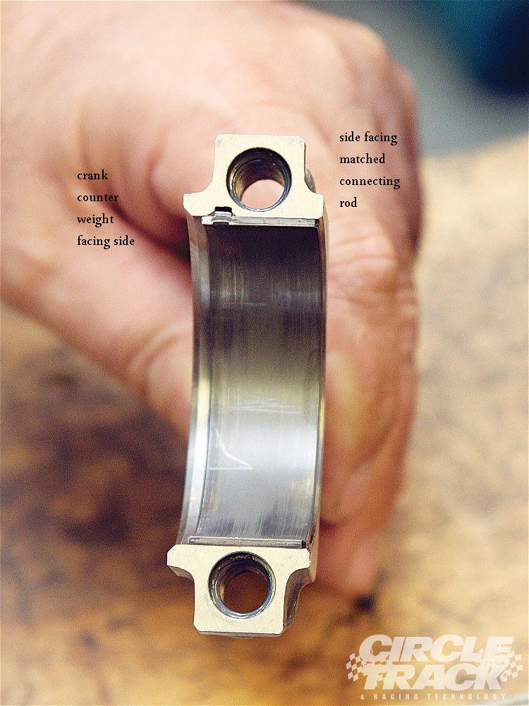
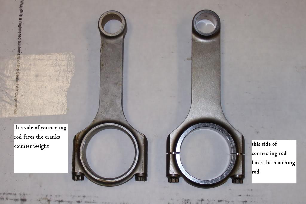
I was very careful during assembly, and measured all my clearances with 2 pieces of plastiguage each, and mixed .001 bearing shells to get them perfect

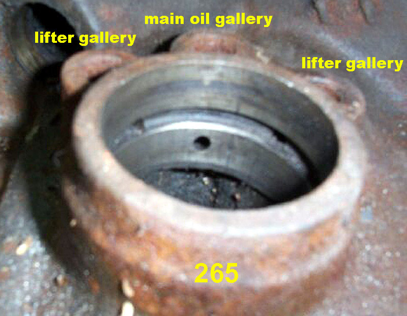
I know my "forgotten plug" is in place, as well as the main gallery plugs behind the cam gear.

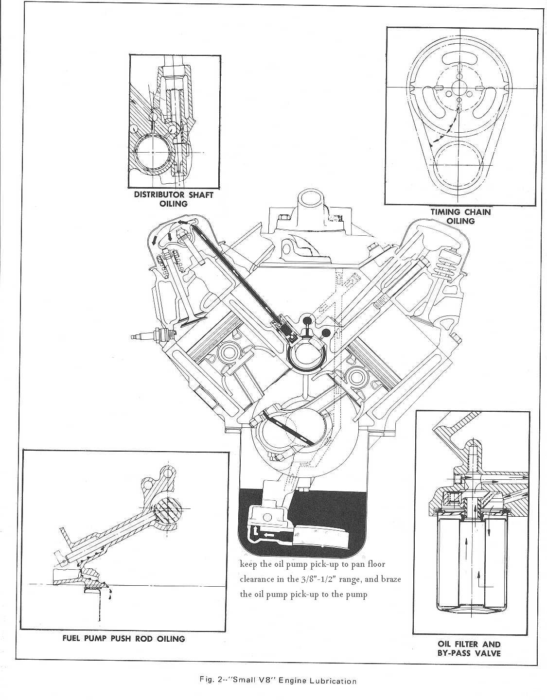
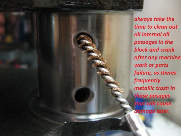
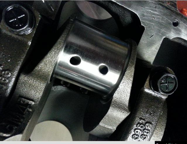
I don't know if there is something restricting oil flow between the main gallery, and the main bearings. Is there a good way to test this?

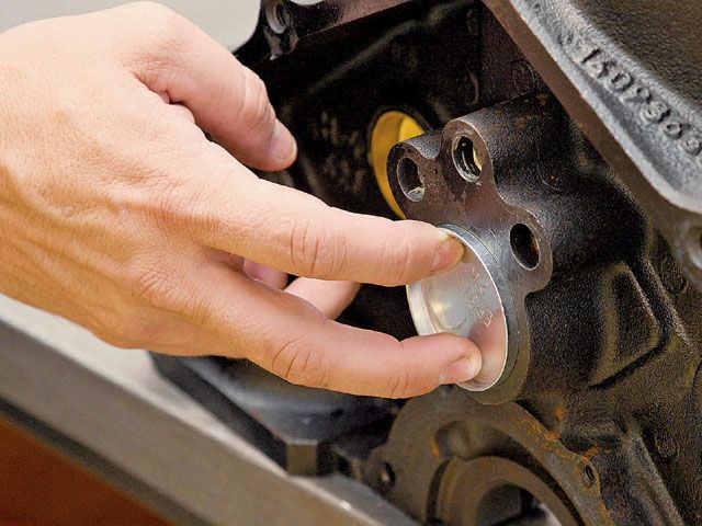
I did figure out that the bolt that plugs the bore for the fuel pump pushrod is missing, not sure if it was ever there, but it doesn't seem to be fed from a pressurized oil gallery, so I don't suspect it's the problem.

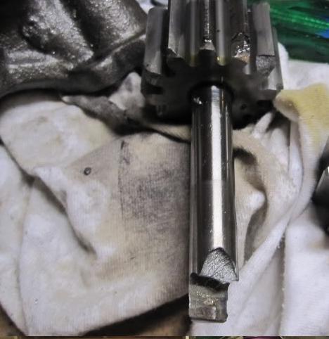
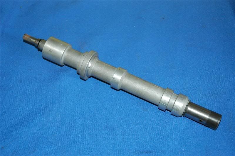
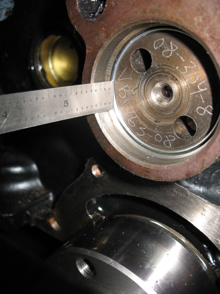
Oil pump doesn't seem very worn on the inside. relief valve moves freely, as does the one on under the oil filter.

I'm going to double check the pickup clearance tomorrow, but it is tack welded on, pressure guage showed constant at speed, and it is the same pan/block/pump that came with the engine that supposedly worked fine for a year or so before I got it. (It sat for a couple of years then I broke it down and cleaned it when I got it.)

Thank you for any advice!
 
Id suggest you post pictures of the bearings as it may be a strong indicator of the cause that will give the info you need to diagnose the problem,
but at this point it sounds like the cam bearing journals or passages in the block are partly blocked with crud restricting oil flow, a close detailed inspection of the block,its internal oil passages and the bearings should point you to the source of the problem. any time you use a block on a new engine build you'll need to remove all the oil passage plugs an rod out the oil passages with a rifle bore brush and a high pressure pressure cleaner and replace the gallery plugs, and cam bearings, crud can get trapped in the groove behind the cam bearings feeding the main bearings, some solvent, high pressure air, and some brushes will help AFTER removing the cam bearings,plugs etc.
use of a separate test gauge would be a good idea

Id also suggest you swap to a quality oil filter of a different brand than you have currently because some filters have been known to restrict oil flow
image_4214.jpg


http://www.bracketracer.com/engine/mains/mains.htm

http://www.harborfreight.com/engine-oil ... erralID=NA

50496.jpg

http://www.idealtruevalue.com/servlet/the-50496/Detail

3416.jpg

http://www.harborfreight.com/10-piece-t ... 95947.html
3171.jpg


THIS is a good example of what happens to bearings if the oil passages are allowed to push small metallic debris, from wear like rockers,valve tips,cam and lifter wear thru the engine, use of a few small magnets, and shrapnel screens helps reduce or eliminate this

bearingd1.jpg

bearingd2.jpg

PLEASE READ THRU THESE THREADS
viewtopic.php?f=54&t=3536

http://www.harborfreight.com/4-piece-ai ... 95159.html

viewtopic.php?f=53&t=2727&p=7078#p7078

viewtopic.php?f=54&t=2187

viewtopic.php?f=51&t=125&p=155#p155

viewtopic.php?f=51&t=1479&p=7526&hilit=+cam+bearings+tool#p7526

viewtopic.php?f=54&t=52

viewtopic.php?f=54&t=4580

viewtopic.php?f=54&t=150

viewtopic.php?f=53&t=3348

SBCOiling.gif

SBOilSystem2.jpg


plas5va.jpg

failure to clean out the oil passages in the block and crank journal cross feed oil holes, resulted in trapped debris being flushed out and scoring the bearings during the test fit process in these bearings, an easily avoided but very common screw-up after a cam or bearing fails and your forced to do a ring, cam,lifter, and bearing replacement
IVE dunked my piston/ring assembly's in a can of MARVEL MYSTERY OIL just before installation with a ring compressor and have never seen the slightest indication of problems either on ring sealing getting the rings broken in, or on tearing the engines down later for inspections the amounts not that great, ideally each one installed adds a bit of resistance but at no time should the short block take over 40 ft lbs ABSOLUTE MAXIMUM to start it spinning,and LESS than 20 lbs to keep it moving, even with all the rings and pistons installed,yes you need to verify the bearing clearances during assembly and IT SHOULD take between 20lbs-25 lbs to start it spinning if the clearances are correct! and LESS than 20 lbs to keep it moving
IF it takes over 40 ft lbs to get it rotating ,youll need too DISASSEMBLE and FIND OUT WHY!

when you get the crank polished take the time and effort to clean out any cross drill oil feed passages and to very carefully de-burr the passage opening edges, as this is a very commonly overlooked issue, below is what at first looks like a perfectly polished crank, with oil feed passages to the rod bearings,
but the deep scratches the oil feed passage openings left in the rod bearing surfaces bare witness, after a single rotation, during a trial assembly show they are HARDLY burr free or ready for use, and obviously he failed to check each rod bearing during the assembly process, and probably ignored , what was very likely un-even or rather excessive resistance to the crank rotation. which should never exceed about 40 ft lbs even with all 8 rod bearings and pistons installed

rodberd1.png

rodberd2.png

failure to clean out the oil passages in the block and crank journal cross feed oil holes, can and has frequently also resulted in trapped debris being flushed out and scoring the bearings during the test fit process in these bearings, an easily avoided but very common screw-up after a cam or bearing fails and your forced to do a ring, cam,lifter, and bearing replacement
bearingoffset1r.jpg

Picture106r.jpg


btw MOLY base lubes are your first and best break-in lube during the first few minutes

http://www.cranecams.com/index.php?show=browseParts&lvl=2&prt=15

http://www.cranecams.com/pdf/548e.pdf


crudinpump.jpg

heres a good example of why keeping small metallic debris like valve locks and rocker arm bearing parts out of the oil pump gears is a good idea, shrapnel screens and magnets tend to reduce that from occurring
CRANES Super Lube Break-In Concentrate is an anti-wear additive formulated with a high concentration of special zinc dithiophosphate to provide sustained protection against cam lobe and lifter scuffing and wear. This oil supplement is to be added to the engine oil for the initial break-in period after the installation of a new camshaft and lifters.
Now it should be obvious that reducing the pressure at the contact point between the lifter and the cam lobe will tend to reduce the tendency for lifter & lobe wear, and increasing the coolant flow at that point helps, so its generally a good idea to remove the INNER spring on DUAL spring valve trains during the break -in process, to reduce pressures while the parts lap in, and a few minutes with some 1000grit sand paper to remove burrs from the lifter edge sure helps in most cases

Part No. 99003-1 -- 8-ounce container
p43452_image_large.jpg

IT should be obvious that you'll need to pre-prime the blocks oil passages and adjust the rockers so oil flows from the rockers with the engine being pre-primed with a priming tool being used BEFORE trying to start any engine with a new cam to insure oil flow begins instantly on the engines start-up,you WON,T get oil to all lifters equally unless the engines crank & cam are spinning,(so during testing spin the engine slowly with a breaker bar or ratchet), because the oil passages feeding the lifters aligns differently at different lifts,your oil leak at the distributor base is normal, but the clearances and flow may be excessive, with a priming tool, some are not nearly to spec. ID measure the diam. of the oil pump primer and then measure the distributor base, Id bet the distributor base is larger and fits better, which reduces the potential for leakage.
SBCprimer.jpg

those bottom two bands form a wall on the oil passage, some guys cut a rounded grove and install an O-RING so the upper band seals too the block, you don,t want to do that to the lower band simply because that's the oil flow source to the distributor /cam gear
20 psi is about normal for your typical 3/8 drill,max pressure is not nearly as important as checking flow, and for leaks where there should not be leaks, with an engine primer tool,Ive brazed a socket to the top of my oil pump primer and use the 1/2" drive air ratchet to drive it, it won,t heat up and burn up like a electric drill will.
don,t get alarmed if you get zero pressure or flow for a few seconds,(the oil filter and passages need to fill first) that's one reason WHY your pre-priming, to get oil flow to the bearings instantly on start up , you don,t want them running without oil flow if you can prevent it even for 20 seconds


crudinpump.jpg

heres a good example of why keeping small metallic debris like valve locks and rocker arm bearing parts out of the oil pump gears is a good idea, shrapnel screens and magnets tend to reduce that from occurring
 
Last edited by a moderator:
for a GOOD job, at a minimum, youll want to remove ALL the oil passage plugs , and clean the block out with solvent and high pressure air, and some rifle bore brushes, run thru the passages.
now obviously you won,t be the first guy that thinks of just installing a new cam, changing the oil and filter , maybe flushing the engine out a bit with a quart of diesel fuel added to the old oil, for about 2 minutes of idle time just before changing the oil etc., and while those practices do occasionally let you get by, thats not the correct route and it leaves a significant amount of metallic crud in the oil passages , the fact that people do occasionally get by with a semi clean engine is tribute to how well the factory lube system and oil filter functions,
but betting on those bearings and the new cam and lifters not being scored by the retained metallic debris, is at best a gamble, where your putting far more than the new cam and lifters at risk

to do the job correctly Remove ALL oil passage plugs. Those are the 2-3 at each end of the cam, depending on if its a bbc or sbc ,don,t forget the one under the rear main cap, and the one in the left deck at the rear. Removing the, main ,bearings and rotating assembly and carefully inspect and clean those components,remove the cam bearings, as the oil passage that feeds oil to the main bearings is behind them, and if there is ANY metallic crud retained AT ALL in the oil passages and if you don,t remove the bearings and clean the oil passages with a brush and high pressure air theres bound to be some retained, you can be certain that metallic debris, which will get flushed RIGHT DIRECTLY INTO your brand-new main bearings, lifters and cam lobes, during the first 10 minutes the new engines running, when you crank the new motor up, resulting in scored bearings and a highly increased chance of the new cam failing


LINK FOR OIL PASSAGE LOCATION INFO [/size]

http://forum.grumpysperformance.com/viewtopic.php?f=38&t=11

SBCOiling.gif


http://www.se-r.net/engine/block_prep.html

http://www.hotrodpitstop.com/engine-block-prep.php
Cleaning Your Engine Block

Engine builders usually charge around $120 to clean a block, and most racers consider it money well spent to avoid the hassle. The engine builders usually use a mild acid or caustic wash, either in a hot tank or a jet sprayer. Whether you choose to do it yourself or have your engine shop handle the duties, make sure the freeze and gallery plugs are removed beforehand so that anything hidden behind them can get out. After all the machining processes are complete, the block needs to be cleaned again to get rid of any accumulated machining oils and metal slivers left over from cutting.


Cleaning is a necessary step even if you are using a brand-new block. New blocks can often have casting slag hanging around in the cracks and crevices, and it becomes a big, gritty problem if not removed before assembly. This is a step you can definitely do yourself. If the block is new, all you need is a water hose and a variety of brushes to make sure you scrub everything. If you are cleaning a rebuild, however, the work gets tougher. You need to use hot water and a cleaner capable of cutting through the grease and grime that builds up just about everywhere. When you are finished, make sure to hit all the surfaces with a light coat of WD-40 or some other type of light oil as soon as the surface has been dried to prevent rust.


Replace The Freeze Plugs

If you have your freeze plugs in place, it's also a good idea to pressure test the block before beginning the big projects. Pressure testing is done by filling the water jackets and then adding air pressure to see if there are any cracks or leaks. Both of these processes should be repeated after all the machine work is done to make sure you didn't cut too much away. Many machinists say they have seen situations in which a chunk of casting slag that was knocked away during one of the cutting procedures opens a pinhole through to a water jacket. The only way to catch this is with a final pressure check before engine assembly begins.

Sonic and Pressure Testing Your Race Engine Block

It doesn't make sense to do machine work on a block that may not even be usable. That's why it's wise to sonic test the block before much effort is put into it. Sonic testing can tell you the thickness of the cylinder walls quickly and easily. Even on a new block, this is important because core shift can cause one side of a cylinder wall to be too thin. Engine builder Peter Guild of PME Engines says he likes to see the cylinder wall thickness at least 0.275 inch. A sonic tester is also capable of catching a block that's just too far gone to be rebuilt again
NEVER GUESS, DEAL IN PROVEN FACT!
Id get out the plasti-gauge and check clearances, don,t guess , know exactly what your dealing with!
if the clearance falls in spec and the bearings look decent they can be re-used, but its foolish to do so if they look overly dirty, worn or don't have the correct clearances
lots of moly assembly lube and spraying any potential moving contact surface with moly spray (like bearings ,lifters rockers) and liberal use of moly assembly lube during the break-in process helps reduce wear issues
keep in mind ALL engines run on USED BEARINGS AND RINGS,LIFTERS,ROCKERS AND CAMS, simply because the first time you start the engine, all the components are no longer new ,out of the box parts,
yes both rings and bearings and contact surfaces like rockers, cam lobes and lifter bases benefit from a coat of moly spray and moly assembly lube
they are now USED PARTS.. but coating all the friction surfaces with a good slick layer of moly based lubricants to protect them until the flow of warm pressurized oil can form a protective barrier is simply smart insurance, especially because moly embeds into micro surfaces, and forms a very effective secondary protective layer of lubricant.


molysp3.JPG

molysp2.JPG

molysp1.JPG

pre-spraying all bearing and valve train components with a moly based spray, helps embed micro moly lubricants in the metallic surface micro fissures , a good paste lube like cranes assembly lube over the spray surface helps insure a good lubricant surface coating, that is far stronger than just the ZINC and PHOSPHATES in oil
crn-99004.jpg

CAREFULLY
.. reading links and SUB LINKS is almost mandatory on this web site!
if you want all available useful related info

http://garage.grumpysperformance.co...earances-and-journal-surface.9955/#post-38385

http://garage.grumpysperformance.com/index.php?threads/bearing-clearances.2726/#post-26440

http://garage.grumpysperformance.com/index.php?threads/oil-system-mods-that-help.2187/

http://garage.grumpysperformance.com/index.php?threads/can-you-reuse-bearings.5544/

http://garage.grumpysperformance.com/index.php?threads/precision-measuring-tools.1390/#post-68194

http://garage.grumpysperformance.co...tion-of-crank-durring-short-blk-assembly.852/

http://garage.grumpysperformance.com/index.php?threads/assembly-lube-summary.6352/#post-68508

http://garage.grumpysperformance.co...ear-articles-you-need-to-read.282/#post-57371

cambreakin.jpg

Molybdenum is a very hard metal with a number of industrial uses.
It is combined with chromium in steel to make the steel harder and more resistant to bending. Most of the bicycle frames produced today use chromium and molybdenum steel. Because the steel is so much harder, the manufacturers can use less, thereby making the frame lighter.

Molybdenum Disulfide (Moly) has been used for decades in lubricating pastes and greases because it is extremely slippery and forms a protective coating on metal parts.

Moly exists as microscopic hexagonal crystal platelets Several molecules make up one of these platelets. A single molecule of Moly contains two sulfur atoms and one molybdenum atom. Moly platelets are attracted to metal surfaces. This attraction and the force of moving engine parts rubbing across one another provide the necessary thermochemical reaction necessary for Moly to form an overlapping protective coating like armor on all of your engine parts. This protective armor coating has a number of properties that are very beneficial for your engine.

squeeze4.png


The Moly platelets that make up the protective layers on your engine surfaces slide across one another very easily. Instead of metal rubbing against metal, you have Moly platelets moving across one another protecting and lubricating the metal engine parts.

This coating effectively fills in the microscopic pores that cover the surface of all engine parts, making them smoother. This feature is important in providing an effective seal on the combustion chamber. By filling in the craters and pores Moly improves this seal allowing for more efficient combustion and engine performance.
nosqueeze.jpeg

This overlapping coating of Moly also gives protection against loading (perpendicular) forces. These forces occur on the bearings, and lifters. The high pressures that occur between these moving parts tend to squeeze normal lubricants out.


Eventually, there is metal to metal contact, which damages these moving parts and creates large amounts of heat. Fortunately, this is not the case with some lubricants.The layer of moly that forms on these moving surfaces can withstand pressures of 500,000 psi, without being squeezed out.

Engineers and scientists have tried for years to use Moly in motor oils but they had been unsuccessful because they could not find a way to keep Moly in suspension. Once Moly was put into suspension it would gradually settle out. It was easy to see it come out of suspension because a black sludge would collect on the bottom of the oil containers. In engines it would settle to the bottom of the crankcase or clog oil pathways and filters.

Engineers have overcome these obstacles. They have developed a process that keeps Moly in suspension and isn’t filtered out. Since that time theproduct has undergone extensive independent testing in labs and in the field for many years to insure that the product stands up to the rigorous needs of today’s engines. With the plating action of Moly reducing friction which reduces heat, this helps keep rings free from carbon buildup, prevents blow-by, decreases emission, and extends oil life.

related threads

http://forum.grumpysperformance.com/viewtopic.php?f=27&t=2886&p=7496&hilit=sprayer#p7496

http://forum.grumpysperformance.com/viewtopic.php?f=27&t=1077&p=2078&hilit=+pressure+water#p2078

http://forum.grumpysperformance.com/viewtopic.php?f=51&t=125

http://www.harborfreight.com/cpi/ctaf/displayitem.taf?Itemnumber=95159
95159.gif

http://www.harborfreight.com/cpi/ctaf/displayitem.taf?Itemnumber=97014
97014.gif


http://www.harborfreight.com/cpi/ctaf/displayitem.taf?Itemnumber=95947
95947.gif


POU-300AFC.jpg

http://secure.armorholdings.com/kleen-bore/product387.html

http://www.midsouthshooterssupply.com/item.asp?sku=0009796231

OBVIOUSLY USE OF A PRESSURE WASHER AND OR A DECENT AIR COMPRESSOR, and SOME good GREASE SOLVENT HAS ADVANTAGES, and use of QUALITY OIL FILTERS and INSTALLING HIGH TEMP, MAGNETS to trap any metallic crud you might miss helps


RELATED INFO YOULL WANT TO READ
http://forum.grumpysperformance.com/viewtopic.php?f=54&t=2080&p=5568&hilit=magnets#p5568

http://forum.grumpysperformance.com/viewtopic.php?f=52&t=282&p=5227&hilit=+magnets#p5227

http://www.kjmagnetics.com/proddetail.asp?prod=D66SH

http://forum.grumpysperformance.com/viewtopic.php?f=54&t=938&p=1581&hilit=+magnets#p1581

http://forum.grumpysperformance.com/viewtopic.php?f=54&t=120&p=867&hilit=+magnets#p867
d48761b8-1524-4912-bac8-46f309f497ad_300.jpg

a334c12a-47fc-4a13-b4f1-75cf0a9a9a74_400.jpg

http://www.homedepot.com/Outdoors-O...splay?langId=-1&storeId=10051&catalogId=10053


HERES A GREAT DEAL OF INTERESTING RELATED INFO

viewtopic.php?f=53&t=619&p=10925&hilit=bearings#p10925

viewtopic.php?f=54&t=3519&hilit=bearings

viewtopic.php?f=54&t=3834&p=10199&hilit=bearings#p10199

viewtopic.php?f=53&t=3449&p=9293&hilit=bearings#p9293

viewtopic.php?f=54&t=2187&p=9097&hilit=bearings#p9097

viewtopic.php?f=53&t=247&p=8348&hilit=bearings#p8348

viewtopic.php?f=51&t=1479&p=7446&hilit=bearings#p7446

viewtopic.php?f=53&t=2727&p=7078&hilit=bearings#p7078

viewtopic.php?f=53&t=2351&p=6453&hilit=bearings#p6453

viewtopic.php?f=53&t=88&p=5709&hilit=bearings#p5709
 
Last edited by a moderator:
Here are pics of the worst of the bearings from each build. First time around, I let it go a little longer, and it ruined the crank, and actually spun one of the rod bearings. I will look through the info you linked, and I'll post if I make any discoveries in the cleaning process.
Thank you for the wealth of information in your response and on your site
build1rod.jpg

build1main.jpg

build2rod.jpg

build2main.jpg
 
thanks for posting the pictures it makes it far easier to diagnose

http://www.thirskauto.net/BearingPics.html

look at the 5th picture down in this link

ID strongly suggest you sit back and read thru these threads and sub links .... read all these links and sub links, as it may save you a good deal of cash in the future

viewtopic.php?f=53&t=2727

viewtopic.php?f=54&t=985&hilit=priming+pump

viewtopic.php?f=53&t=852&p=1812&hilit=+rotation+resistance#p1812

viewtopic.php?f=54&t=2376&hilit=pickup+pump+clearance

viewtopic.php?f=54&t=3376&p=8912&hilit=+oil+filter#p8912

viewtopic.php?f=54&t=52&p=8265&hilit=+oil+filter#p8265

viewtopic.php?f=54&t=1800&p=5526&hilit=braze#p5526

viewtopic.php?f=53&t=247

7168.jpg


"OIL STARVATION

This photo shows a bearing suffering from excessive friction and fusing signs caused by lack of oil.
Some of the causes of lubrication failure are a blocked oil filter cartridge, broken oil line, failure of the oil pump, or excessively low oil level in the working engine. "

Id say your dealing with ,
a lack of pressurized oil flow on start up, or a good deal of metallic crud in the oil passages, or a combo of both
but a rough surface finish or out of round crank journal that's not polished and clearanced correctly can result in similar damage

heres some potential problem areas
forgetting to coat the bearings with moly assembly lube
forgetting to pre-prime the engines oil passages
a defective oil filter design
a defective oil filter adapter
a defective or improperly installed oil pump or the oil pump pick-up is mounted too close to the oil pan floor
a defective or improperly installed oil passage plug

during the short block assembly you should rotate the crank after each connecting rods installed with a torque wrench, set on 30 lbs---as it should not require that much resistance to get it spinning and LESS to keep it spinning even with NEW rings , if it requires 35-38lbs, you should find out whats wrong before proceeding further if it requires that much torque, somethings not clearanced correctly
ONE common mistake (obviously not the only potential problem) is not having the beveled edge of each pair of rods and each pair of bearing shells face outward to the counter weights or use of the wrong bearing type, I generally prefer (H) bearings as they have a larger beveled edge, one other common problem is failure to gap the rings correctly


DO NOT TRY to START a new engine UNTIL youve got oil flow from EVERY ROCKER as you PRIME the engine and SLOWLY rotate it by hand AS you PRIME the oil passages with the correct oil pump priming tool


notice the oil passage location in the block, IT MUST LINE UP WITH THE OIL FEED HOLE IN THE UPPER BEARING SHELL
OilTemperatureVsMileage03.jpg


16.JPG

you must use the correct oil filter adapter
enginerebuild96.JPG

upper grooved bearings must have the oil feed holes align with the block feed holes
13.JPG


the GROOVED BEARING GOES INTO THE BLOCK SADDLE and THE HOLE IN THE BEARING MUST BE LINED UP

Oilinggroove.jpg

keep in mind the GROOVE under the cam bearing must line up with the oil feed hole in the bearing
 
http://www.cdxetextbook.com/engines/reb ... shaft.html

Points to note

* Make sure all parts and components are clean prior to assembly.
* Ensure bearing oil holes line up with oil galleries.
* For all types of engines it's very important to put a dab of silicon sealer on each side of the seal where the rear cap meets the metal of the block. If you don't do this, oil will leak from the rear of the block because there is no gasket here.
* Have all the torque specifications for the engine on hand.

Part 2: Step-by-step instruction

1. Clean and prepare
Clean the saddles of the block, and do the same to both sides of all the bearings to make sure there's no dust or build up from the previous lubricant. Clean the crankshaft itself as well.
2. Install bearings
Install the main bearings and double check that the oil holes line up with the ones in the block. At the same time, clean the caps and wipe and install the bearings for them as well.
When the motor starts up for the first time and while it's running, the crankshaft requires more lubrication than the camshaft. Engine assembly lubricant is better for the camshaft journals and lobes because it is specifically designed to provide the start up and break-in protection that high quality bearings deserve. Make sure you wipe some on the faces of the thrust bearing as well.
3. Install two-piece main seal
If the engine has a two-piece main seal, Install the upper half before lowering the crankshaft into place. On a neoprene rubber seal, the pointy lip must point towards the inside of the motor. When you press it into place use the plastic protector shim between the seal and the block to keep the rubber back of the seal from being damaged by the sharp edge of the block. For engines with an older type of rope seal, work the rope into the groove of the block and then use a large socket to tap it deeper into the groove. Cut off the excess flush with the block using a razor knife, or just clip it off with some cutting pliers. You can bolt the cap in upside down for some motors to install the rope seal in the rear cap. in either case, put a little oil or assembly lube on the lip or the rope so the seal won't burn out on start-up.
For all types of engines it's very important to put a dab of silicon sealer on each side of the seal where the rear cap meets the metal of the block. If you don't do this, oil will leak from the rear of the block because there is no gasket here. Spread a little on the tips of neoprene or rope seals as well.
4. Install crankshaft and caps
Be gentle as you lay the crankshaft in place. Then, lubricate each of the caps and put them in place. Each bolt that goes into the engine needs to have some type of lubricant on it's threads. The main cap bolts should have some engine oil on the threads to reach the proper torque setting. Make sure the bolts are threaded in a few turns then tap on the caps to seat them.
If you have rubber rear main seals, remember to use the protector shim on the seal when you put it in the rear main cap, and of course, rubber or rope seals get a bit of oil on the seal itself. The contact surfaces of the cap needs to be clean to seal correctly against the silicone on the block. Before the main cap bolts can be torqued, they should also have some oil put on the cap where the head of the bolt is going to contact it.
Make sure you have all the torque specifications for your engine readily available. You should be able to find what you need in the correct repair manual.
Carry out the final torquing of the main caps in three increments. Whatever the torque specification, tighten the bolts first to one third that amount, then two thirds, then again to final specification. If you have four bolt main caps, do the inner bolts first.
Leave the cap that has the thrust bearing in it to last. When the other caps are correctly tightened, hit the back of the crank with a rubber mallet or hammer on another hammer to line up and seat the thrust bearings. Now go through the three increments to torque the cap with the thrust bearings, inner bolts first if it's a four bolt cap.
5. Install one-piece main seal
For a one piece rear main seal, you need access to the rear of the block. This type of engine uses an adaptor that bolts to the block. This way the rear main seal is fitted in after the adaptor is sealed and bolted in place.
To install the seal, you will probably have to take the block out of the stand so that you have access to the rear area of the block, then lift the engine back onto the stand after installing the seal. You may be able to install the adaptor while it is on the block if you can get it past the engine stand adaptor. Alternatively, you can leave the main seal and install it later.
 
so after some work, and after much time looking through the forums, here's where I'm at:

heres some potential problem areas
forgetting to coat the bearings with moly assembly lube (I used red line assembly lube on bearing fronts, and dried all backs with laquer thinner)

forgetting to pre-prime the engines oil passages (primed system with a drill, and old distributor shaft with gear ground off. I verified pressure on the guage, but didn't look at the rockers to see if oil was in the top end.)

a defective oil filter design. I used a new fram ph5 filter,

a defective oil filter adapter (The filter adapter is the standard http://www.summitracing.com/parts/SES-3-60-08-900/?rtype=10 that was the one used previously in the engine. I did add a cooler adapter like this: http://www.summitracing.com/parts/FLX-3967/, and I can't see how it would be causing a problem. )

a defective or improperly installed oil pump or the oil pump pick-up is mounted too close to the oil pan floor. The pump appears ok, there is some light marking on the teeth where you would expect, and also very light wear on the case above and below the gears. The pickup screen is 3/8" away from the floor of the pan.") I plan on buying a new pump when I put it back together, since I have no way to test the existing one.

It seems significant that the wear gets worse on the mains and rods from front to back, but I can't think of any reason that would explain that happening.

Judging by the speed that my bearings went out, I feel like there should be something glaring that I'm missing. Without removing the cam bearings, I removed the gallery plugs in the rear, and blew some air and carb cleaner through the main passages, and it sure doesn't seem like there's any restriction in the grooves. Does it make sense to somehow plug all the holes that I know about (galleries/main bearing oil holes) and sort of pressure test the system, through the oil pump hole to see if there are any places for oil to escape that I don't know about?

I'm trying to give it one more shot at the poor mans rebuild without going the whole 9, breaking the engine completely down, and racking up a huge bill. I'm running out of ideas
Thanks!
 
I think your making a major mistake if you don,t replace the cam bearings and flush out the block passages
new cam bearings are less than $20 in most places
example
http://www.summitracing.com/parts/DUR-CH-8/

http://www.summitracing.com/parts/SUM-173000/

you can buy or rent the tool to install them
http://www.summitracing.com/parts/SUM-900130/

remember the rear cam tunnel freeze plugs not a 2" freeze plug its something like 2 1/32"
http://www.summitracing.com/parts/DRT-3 ... 5.7L%2f350
0183.jpg

notice theres a SLIGHT STEP the plug seats against in most cases the rear of the plug seats even with the block surface
IVE always seated the plug edge just level with or a bit deeper than flush with the back of the blocks plug recess boss and found that works, remember to use a brush on sealant on the plug edge, and use a punch in three places to lock it in place
DisplayImage.asp

rearfreezepluginstallation.jpg


viewtopic.php?f=57&t=869&p=1357&hilit=+sealant#p1357

Oilinggroove.jpg


keep in mind the GROOVE under the cam bearing must aline with the oil feed hole in the bearing


http://www.summitracing.com/parts/FLX-3967/

ID suggest NOT using this adapter or an oil cooler until AFTER your engines well broken in, because its fairly common for those adapters and oil coolers to cause problems if improperly installed and removing that as a potential source, of your oil flow problem makes a good deal of sense
 
my #5 (rear) main bearing plastiguaged clearace is a little lower than my book recommends, and my crank/pistons took 23lbs to rotate with a torque wrench. should I be alarmed?
Thanks,
CB
Build3
main bearing clearance
1 0.00175
2 0.00175
3 0.00175
4 0.002
5 0.0015

rod bearing clearance
1 .0013-.0015
2 0.00175
3 .0013-.00175
4 .0013-.00175
5 .0013-.00175
6 0.0013
7 0.00175
8 .0015-.00175

rod end gap
1 & 2 0.014
3 & 4 0.012
5 & 6 0.009
7 & 8 0.009

oil pump pickup 7/16-cover 9/16 to screen
crank end play 0.002

new oil pump/screen
new lifters
new intake manifold
all oil galleries unplugged, and brushed/sprayed out with laquer thinner. didn't seem to be any blockage in oil galleries or behind cam bearings.
 
cb9501 said:
my #5 (rear) main bearing plasti-guaged clearance is a little lower than my book recommends, and my crank/pistons took 23lbs to rotate with a torque wrench. should I be alarmed?

23 ft lbs to rotate the assembly is fine but the clearances are all on the tight end or too tight, in my opinion, Id suggest you get the clearance range in the .002-.0025 range,MINIMUM, and coat the NEW bearings with moly assembly lube,after verifying the clearances and don,t forget to pre-prime the oil passages.... bearings can be purchased that are .001 over-sized, measure carefully

Callies, and several other manufacturers of bearing and crankshafts , research has shown that a bearing clearance between 0.0020 and 0.0025 inch is ideal in almost all street and race applications.


Rod bearings 0.002 - 0.025" , side clearance 0.010 - 0.020"

Main bearings 0.002 - 0.003" for most engines ( 0.020-0.025 bearing clearance on small blocks, .025-.027 bearing clearance is about ideal, on big blocks ), 0.005 - 0.007 crankshaft end play

Piston to head clearance 0.038 MINIMUM including gasket (.038-.042 quench is what you want with steel rods)(steel rods), 0.060" MINIMUM quench aluminum rods

Valve to piston clearance MINIMUM 0.100" exhaust , 0.080" intake NO VALVE FLOAT
Recommended: 0.080 intake, 0.100 Exhaust (steel rods) 0.100 intake, 0.120 Exhaust aluminum rods

bearing1a.jpg

bearing2a.jpg

bearing3a.jpg

http://www.summitracing.com/parts/KGB-CR848HPSTDX/

http://www.summitracing.com/parts/CLE-MS590HK1/

read this
viewtopic.php?f=53&t=2726

Thanks,
CB
Build3
main bearing clearance
1 0.00175
2 0.00175
3 0.00175
4 0.002
5 0.0015

rod bearing clearance
1 .0013-.0015
2 0.00175
3 .0013-.00175
4 .0013-.00175
5 .0013-.00175
6 0.0013
7 0.00175
8 .0015-.00175

rod end gap
1 & 2 0.014
3 & 4 0.012
5 & 6 0.009
7 & 8 0.009

oil pump pickup 7/16-cover 9/16 to screen
crank end play 0.002

new oil pump/screen
new lifters
new intake manifold
all oil galleries unplugged, and brushed/sprayed out with laquer thinner. didn't seem to be any blockage in oil galleries or behind cam bearings.
 
After talking to the shop that sent my crank out to be turned, they insisted that my clearances were fine as long as the crank turned freely. I buil the motor, and still have some interesting oil pressure symptoms. Here is what a typical scenario looks like. I am taking measurements off of a mechanical, and electrical guage.

At idle cold, pressure sits around 50psi. I can drive 3500rpm for as long as I want and pressure sits at 59-60psi. When I let off throttle, at idle the pressure drops to 30psi. If I drive 4500rpm for 1 minute, the pressure sits at 58psi, then when I let off, at idle the pressure drops to 15psi. After cooling, the cycle starts over again.

Remember that this is a boat, and is expected to run at 4500rpm forever without a problem. I installed a melling m55hv pump which was the same one that was installed on the crate (marine) engine that I bought used. My pan took 8 qts to reach the full line, and pump screen is 9/16 off the floor of the pan. It has a flat baffle bolted to the main caps, and another small flat baffle in the bottom front of the pan.

Am I pumping the pan dry? are my bearings just getting hot and expanding? pressure never drops when at throttle, only after I let off the throttle.

I have to pull the engine to find a leak in the back (cam plug?) anyway, so I wonder if I should put a standard pump in, or change my relief spring to a lower pressure bypass?

Any idea on best way to troubleshoot? I was thinking of sticking some semi rigid tube in the oil dipstick hole, and sucking oil through it so i could measure where the oil level is in the pan while driving at various rpms to rule out an empty pan.
Thank You!
 
well I can save you some testing,
if your blocks drain back holes in the lifter gallery and heads are not restricted theres virtually no chance the pumps pumping the oil pan dry.

as long as your engine maintains a steady 45-50 psi at 4500rpm, its almost a total non-issue that the pressure falls to 15 psi when you let off the throttle,
personally Id suspect that when your running 4500rpm the bow of the boats inclined upwards and the oil pan sumps tend to remain full,and when you let off the throttle the nose drops significantly and the rapid deceleration is allowing the oil in the pan to rapidly shift forward in the oil pan ,away from the oil pump pick-up,resulting in your pressure drop.The melling oil pump 10552 is a 10% more volume not pressure
It comes with two springs
If you use it with the "plain" spring it will be about 60lbs & the pink one is about 70lbs
this pump is a good choice for the vast majority of SBC engines

read thru these threads , the info in them should help you locate and cure your problem


viewtopic.php?f=54&t=1280

viewtopic.php?f=54&t=3536

viewtopic.php?f=54&t=52

viewtopic.php?f=54&t=3053

viewtopic.php?f=54&t=615
 
Back
Top