Re: Understanding Valve Spring Bind Height +.060" Safety Mar
Indycars said:
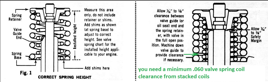
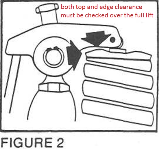
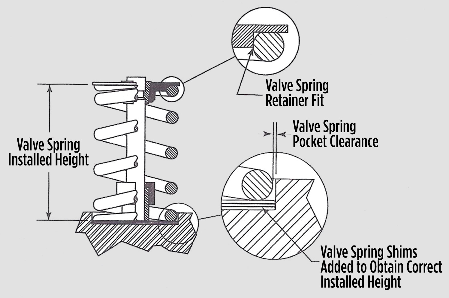
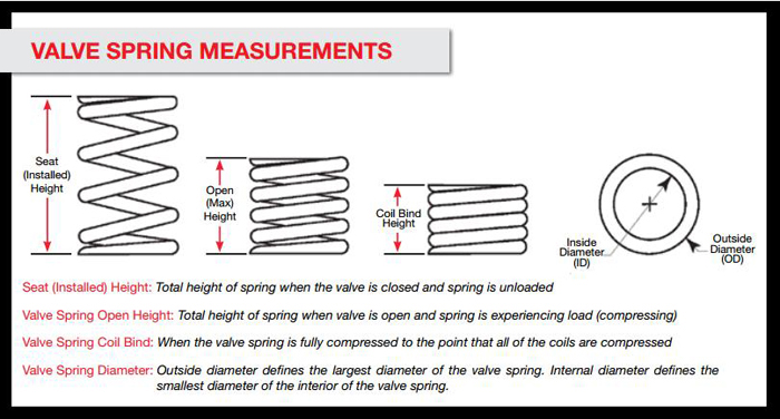
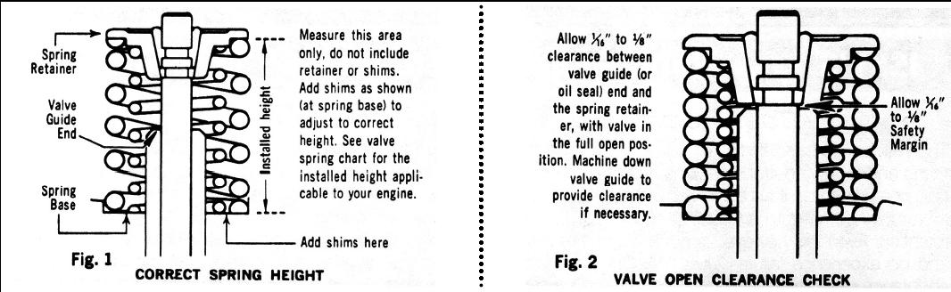
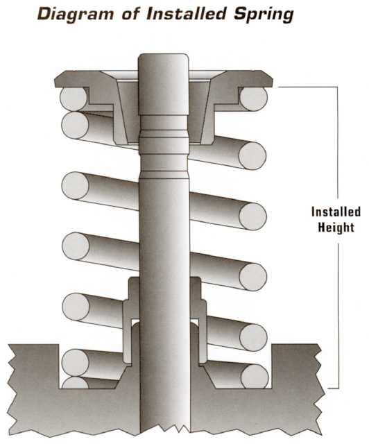
Quite often I see this graphic showing 0.060" between the coils. If this was right, then the actual safety margin would
equal nearly 1/4" and NOT 0.060". With roughly 5 coils in the spring then there are 4 gaps between the coils, therefore
4 x 0.060 = 0.24" or nearly 1/4". Looking at the graphic also makes me think that I could use a wire gauge of 0.060"
and measure directly between the valve spring coils at maximum valve lift to determine if I had the correct clearances.
What we are really trying to determine is if the spring height at maximum valve lift is 0.060" greater than spring bind height.
Maybe I don't understand this concept.......am I right or wrong ???
http://www.racingsprings.com/
READ THIS THREAD AND RELATED LINKED INFO
http://garage.grumpysperformance.co...rdering-correct-custom-length-pushrods.14241/
http://garage.grumpysperformance.co...-loads-and-installed-height.10709/#post-46658
your correct the illustration confusing and miss represents the clearance they MEAN .060 TOTAL clearance not .060 per coil
coil bind height + plus lift + plus .060 clearance = equals max cam lift
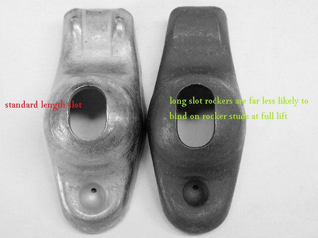
long slot rockers are far less likely to bind on rocker studs
example if coil bind is 1.25" and installed height is 1.90 " then the .060 minimum clearance, being mandatory , leaves a max cam lift of .590
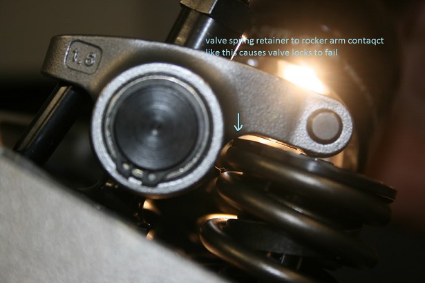
the rocker is basically a pivot point between the valve and push rod roughly centered on the rocker stud, if the rocker is not running smoothly thru its intended arc theres an excellent chance you've got clearance or rocker geometry issues,you will need to verify the correct rocker geometry then order the push rod length to match the correct rocker geometry and clearances in the valve train.
youll need to verify you have enough valve train clearance at full valve lift to both prevent the retainer from getting closer than .060-.090- from the valve seals and .060 minimum from spring bind or having the spring fully compressed
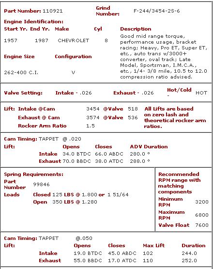
If your confused by the terms, lets try this, using this cam and the spring it lists
once installed the valve spring max length is the installed height,
max lift is installed height minus .060 minus coil bind
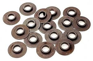
if you used these valve springs
Crane Cams#271-99846-16
Single Valve Springs
Outside Diameter: 1.255"
Inside Diameter: .870
Seat Pressure: 125 LBS @ 1.800"
Open Pressure: 383 LBS @ 1.200
Coil Bind: 1.100"
Rate (LBS/IN.): 428
Max Lift: .640
Set of 16
coil bind is 1.100 so minus .060 from the installed height of 1.800, you get 1.160 lift,subtracted from 1.800 (.640 clearance) but the valve only forces the spring to compress to max valve lift which will be less than the .640 max lift, while the installed height of 1.800 minus the max permissible lift with that spring 1.800-1.160= .640 in this case the cam lobe lift on the lifter multiplied by the rocker ratio provides a .536 max spring compression, since you have a max usable lift clearance of .640 available with that spring at that installed height,in this case, the .536 lift the cam lobe provides,compresses the valve spring about .104 less than the max permissible lift so clearance will be fine and the valve lift will never reach the full theoretical valve spring compression or load rate listed, it will with the stated load rate of 428 lbs per inch of compression see a lower rate than the listed 383 lbs as .536 lift x 428 lbs per inch of compression= roughly 230 lbs
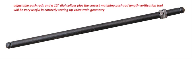
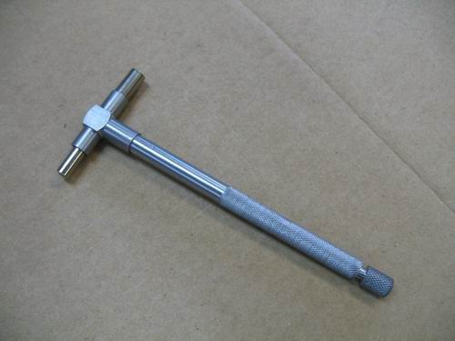
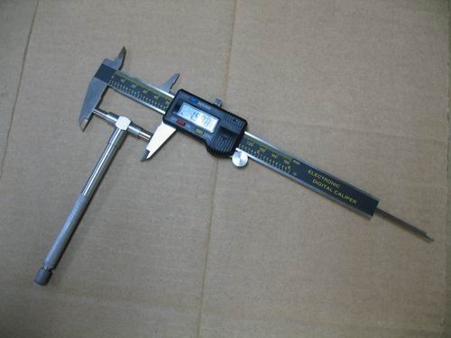
once youve got that correct you use the valve spring/rocker geometry check tool to get the APPROXIMATE LENGTH REQUIRED, and
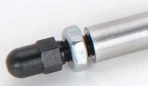
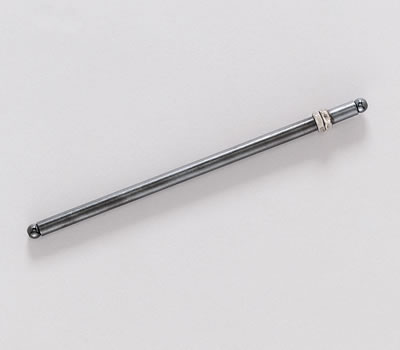
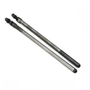
an adjustable length push rod
https://www.crower.com/clearance.html?cat=1541
you might want to buy a few of these while they are on sale at a reduced price
heres a bit of useful related push rod length info (POSTED HERE) youll want to select the correct set or SETS for your shop
Big Block Chevy, Standard Length Big Block Intake 3/8" / .080" 8.275"
295-7941-8 Big Block Chevy, Standard Length Big Block Exhaust 3/8" / .080" 9.250"
295-7969-8 Big Block Chevy, Standard Big Block +.100" Long Intake 3/8" / .080" 8.375"
295-7979-8 Big Block Chevy, Standard Big Block +.100" Long Exhaust 3/8" / .080" 9.350"
295-7951-8 Big Block Chevy, Standard Length Big Block Tall Deck Intake 3/8" / .080" 8.675"
295-7961-8 Big Block Chevy, Standard Length Big Block Tall Deck Exhaust 3/8" / .080" 9.650"
295-7800 V8 396-454 Retro Fit Pushrod Set, Intake & Exhaust, 1965-Present
3/8" / .080"
3/8" / .080" 7.725 Int.
8.675 Exh
295-7913-16 Small Block Chevy, Standard Length Small Block Chevy 3/8" / .080" 7.800"
295-7984-16 Small Block Chevy, +.100" Long 3/8" / .080" 7.900"
295-7934-16 Big Block Ford, Standard Length Ford `72-'78 429-460 3/8" / .080" 8.550"
295-7951-16 Big Block Ford, Standard Length Ford `69-'71 429-460 3/8" / .080" 8.675"
295-7582-16 Oldsmobile, Std Length 455 5/16" 9.550"
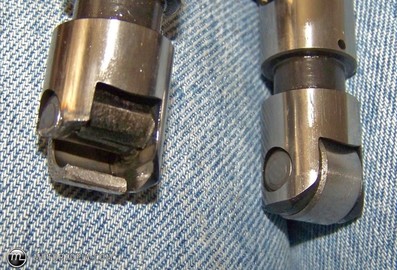
you should very carefully inspect any used rockers or push rods before you use the two, as any previous wear areas will in most cases cause rapid wear on the new component mated to the worn surface, and obviously the rockers must be clearanced correctly and have obvious oil flow from the push rods
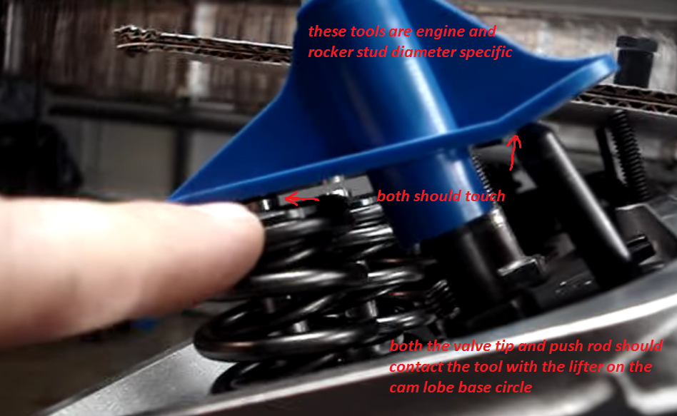
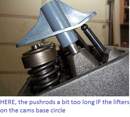
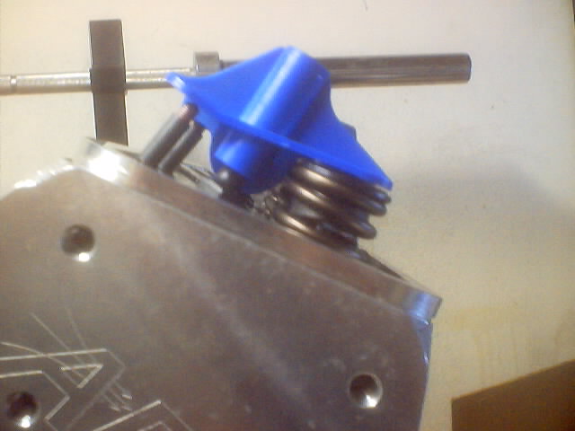
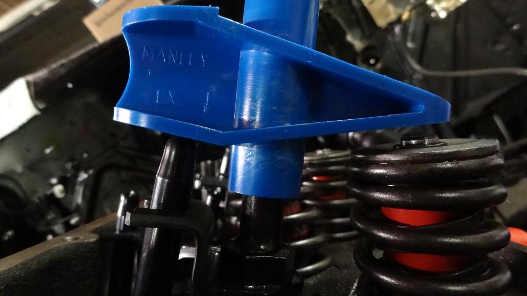
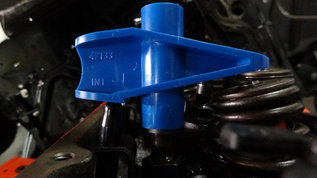
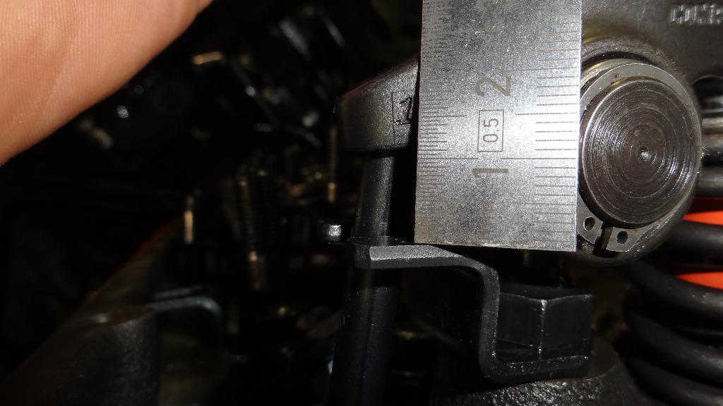
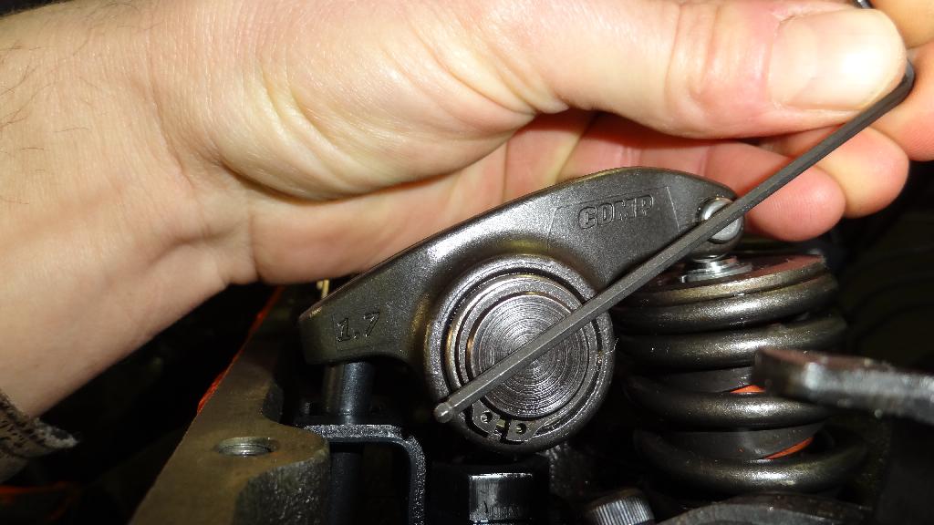
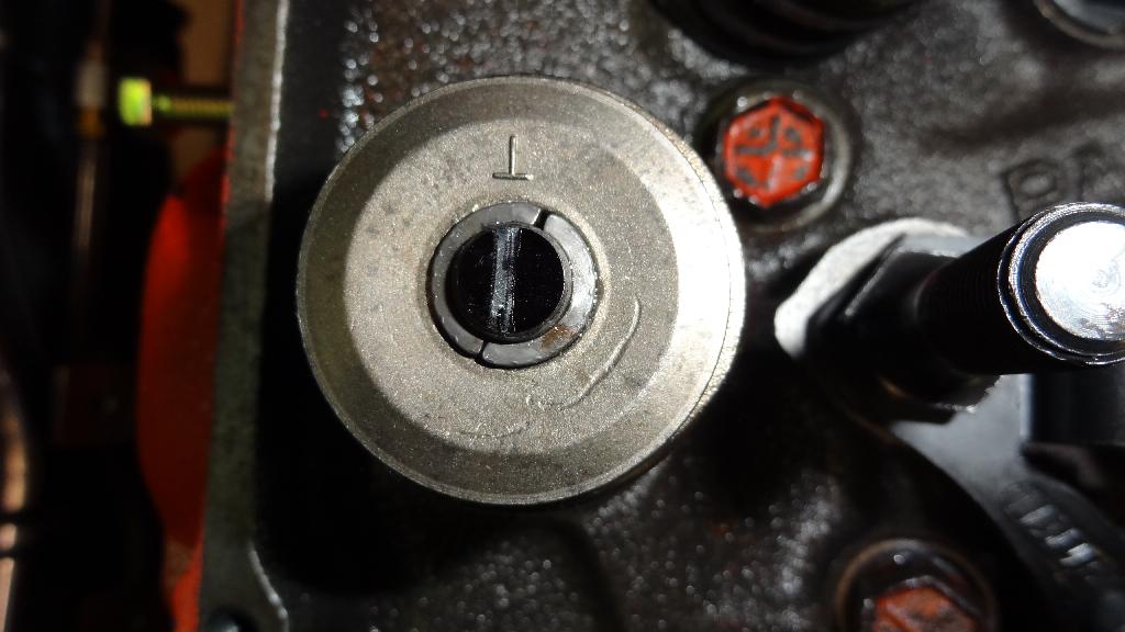
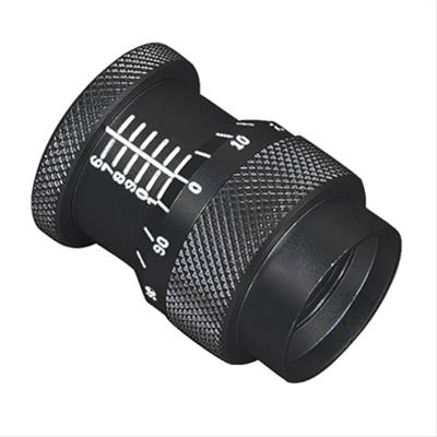
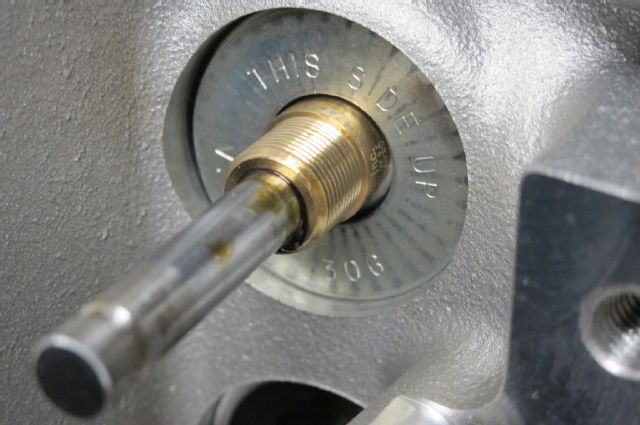
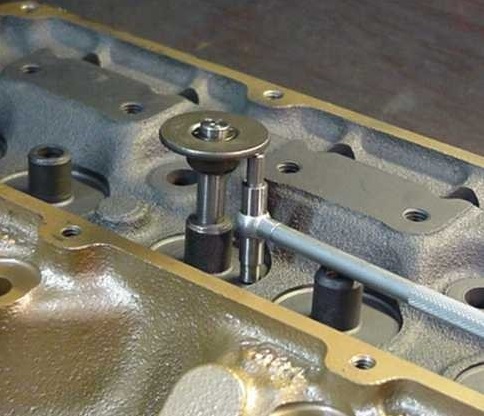
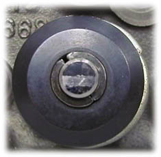
HERES A SBC with a push rod checker installed showing an obviously too long for the application push rod.
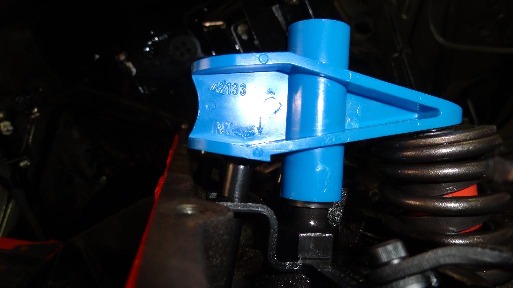
since the early mark IV BIG BLOCK engines use two different length push rods (INTAKE/EXHAUST) the checker is designed to be reversible, and marked to indicate which position it needs to be used with, to indicate the correct length push rods
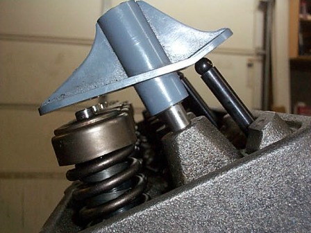
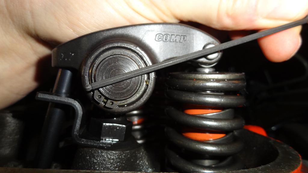
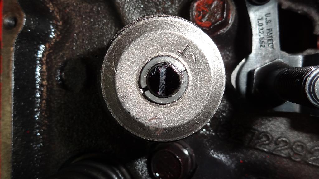
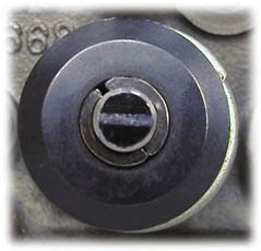
notice in the pictures directly above and below it appears the push rods are a bit too long
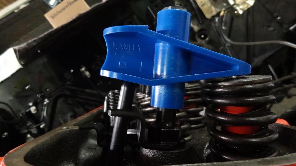
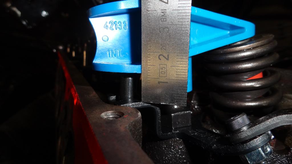
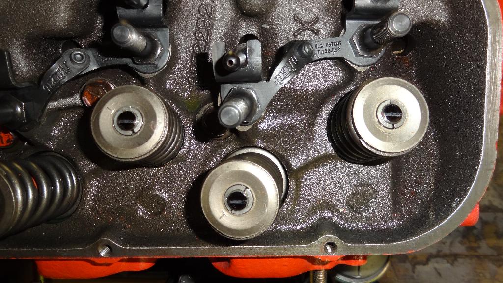
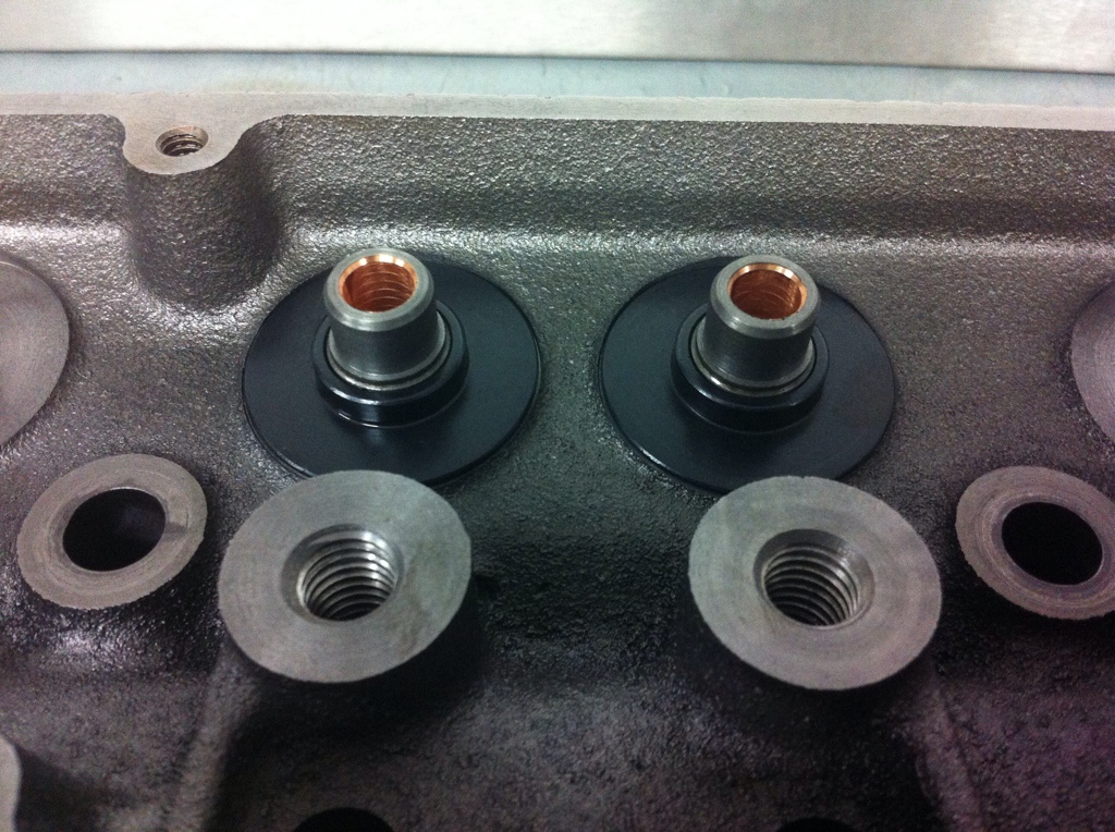
notice in the two pictures above the pushrods are the correct length as the checker sits on both the valve tip and push rod tip
obviously the push rods must be long enough to clear the push rod guide plates rockers through the full arc of movement and not bind on the springs retainers or rocker stud at full lift or while the lifters seated
push rods should also not rub on the guide plates at any point in the arc as it moves the valve from seated to full lift and back too seated
read link
http://www.racingsprings.com/Store/1400 ... ive/sku/32
http://www.racingsprings.com/Store/1200 Series/sku/5
viewtopic.php?f=52&t=181
viewtopic.php?f=52&t=1376&p=3030&hilit=pushrod+length+checker#p3030
http://www.stockcarracing.com/tipstrick ... eight.html
http://www.hotrod.com/techarticles/engi ... to_15.html
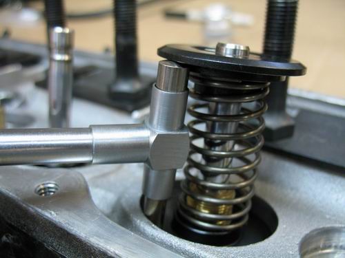
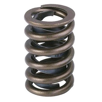
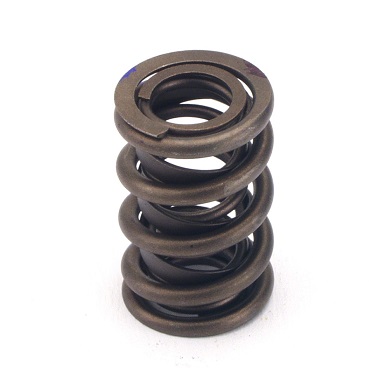
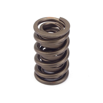
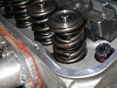
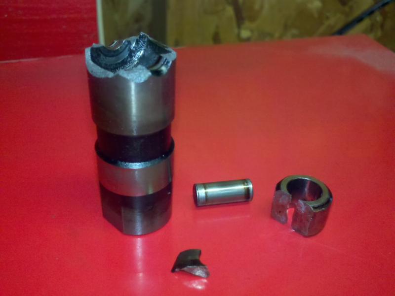
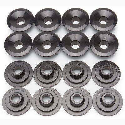
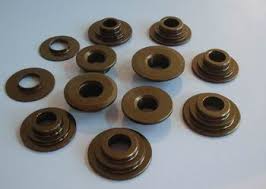
occasionally youll see guys post advice , to remove the inner of the two springs on dual valve springs during the cam break-in process to reduce the lifter to cam lobe load rates, thus reducing the potential for rapid wear during the critical break-in process,the problem I see occasionally is that some guys confuse single valve spring with dampers with dual springs.
typically chevy valve springs use single or dual valve springs usually with an inner friction damper
single valve spring with friction damper ABOVE
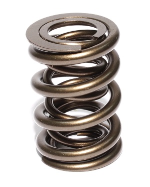
dual valve springs with friction damper (BOTH PICTURES ABOVE)
dual valve springs without damper
as always its isolate and carefully test,don,t assume you know whats causing the noise, or problem like most guys do, and try to prove it, look at the facts!as you find them,and let them lead you to the cause, don,t ever assume a new part can,t be defective or that you could not have installed it incorrectly, WE ALL SCREW UP OCCASIONALLY!. THINK THINGS THRU,BE OBSERVANT! Id suggest you pull the valve covers, and carefully inspecting the rockers and valve train components for indications of excessive wear,and look at the valve springs and check for coil bind , and rocker to rocker stud clearance,and rocker to jam nut clearance, rocker to retainer clearance,especially if the cam you installed has over .480 lift and your still using the stock valve springs,and then place your hand on each rocker as the engine idles and listen for changes in the sound and feel the rocker movement, a defective or improperly installed rocker arm,or one binding on the jam nut can and will make that sound and exhaust rockers are more prone to fail, if you adjusted the rockers without having the engine idle try it the old way at idle ,yeah, I know,what you heard, try it any way.
you might also find that pulling one spark plug wire off the distributor cap at a time and replacing it then moving to the next and removing that one, etc. etc. will help you locate the cylinder causing the ticking sound, by the change in sound when that cylinder does not fire.
you might also do a compression test and check your ignition timing curve, look for vacuum leaks and post clear detailed pictures of each spark plug labeled as to the cylinder as its condition can tell you a great deal about the combustion in that cylinder
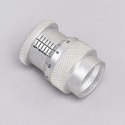
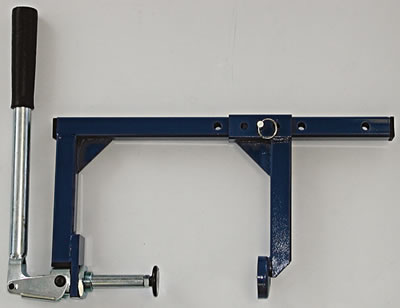
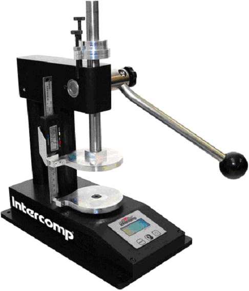
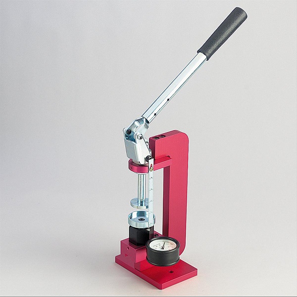
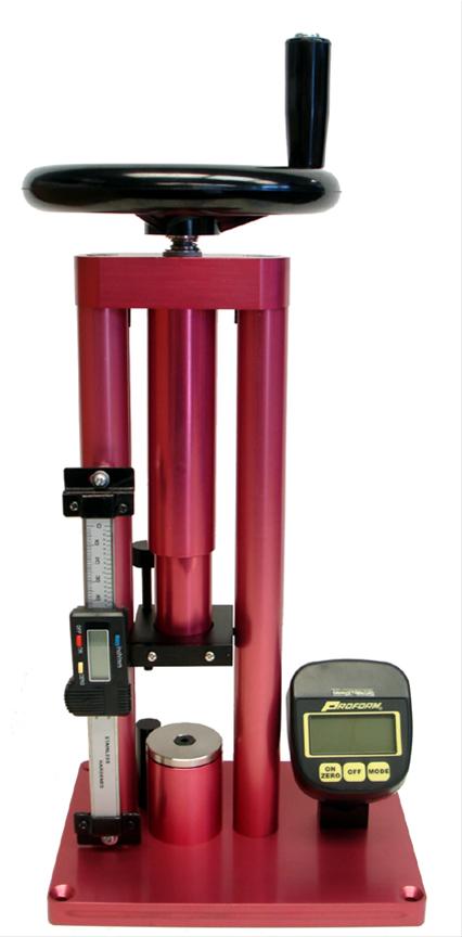
A VALVE SPRING LOAD TESTER IS EXPENSIVE, BUT A GREAT TOOL TO HAVE
http://streetperformanceusa.com/i-72754 ... ester.html
http://www.summitracing.com/parts/pro-66775
http://www.summitracing.com/parts/pro-66776/overview/
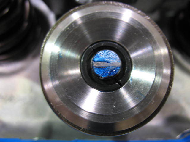
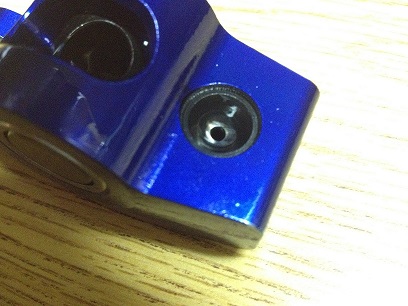
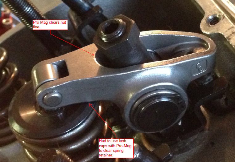
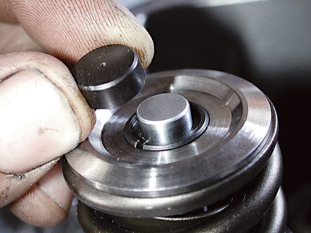
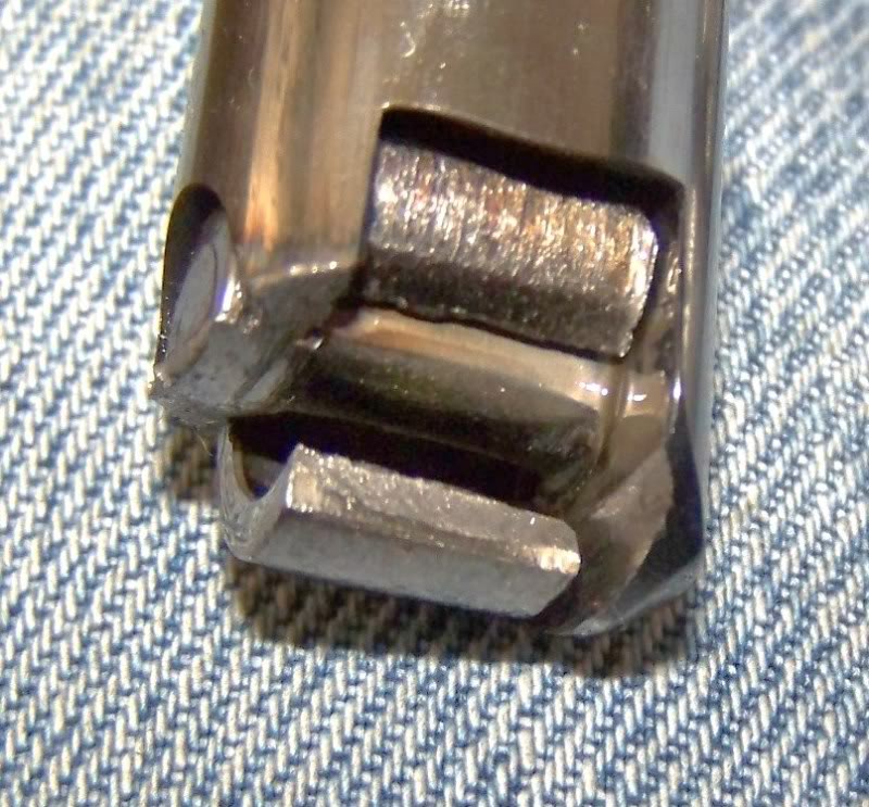
BE aware you need to verify rocker adjustment lock nut to rocker slot clearance and yes it varies even with the same manufacturers different rocker designs
at times lash caps or longer push rods will be needed to change the valve train geometry to gain rocker clearance or get the proper geometry
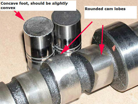
AND YES CAM LOBES AND LIFTERS FAIL..even ROLLER LIFTERS