there's a good deal of info in the links and sub links,
you'll really need THAT DETAILED info,
the LINKS AND SUB LINKS
, AND those SUB -SUB LINKS and the info they contain,
so don't skip over reading them carefully.
you'll find many guys claiming that aftermarket CPU chip upgrades help a great deal
Iv'e found some help marginally but many actually hurt performance
http://www.iroc-z.com/articles/articlepages/1990-3Chips Article by Cliff Gromer, Super Stock, 1991.htm
http://tpiparts.net/85_89_maf_sensors/
http://www.1aauto.com/mass-air-flow..._content=EAF&gclid=CO-WoOWzqMoCFZOCaQod8M0L2A
http://garage.grumpysperformance.com/index.php?threads/testing-1985-89-m-a-f-sensor.1475/#post-43635
http://www.eecis.udel.edu/~davis/z28/ecm_swap_730/
http://www.eecis.udel.edu/~davis/z28/ecm_swap/
viewtopic.php?f=36&t=10946
http://tpiparts.net/tech_articles
viewtopic.php?f=80&t=728&p=43477&hilit=camaro+sensors#p43477
viewtopic.php?f=32&t=169
viewtopic.php?f=80&t=2861&p=7410#p7410
viewtopic.php?f=36&t=10567&p=45108#p45108
http://tpiparts.net/305_tpi_to_350_tpi_conversion
http://tpiparts.net/installing_tpi_on_your_vehicle
http://hotrodlane.cc/PDFFILES/TPIStory.pdf
http://www.eecis.udel.edu/~davis/z28/ECMs/86to92.txt
http://tpiparts.net/85_89_maf_sensors/
http://tpiparts.net/90_92_speed_density_sensors/
http://tpiparts.net/retrieving_and_clearing_error_codes
http://tpiparts.net/1227730_pinout_diagram
http://garage.grumpysperformance.co...otal-panic-over-an-easy-fix.12177/#post-58940
read these links and
related sub links
pull trouble codes
http://garage.grumpysperformance.co...oven-facts-if-your-in-doubt.13051/#post-84695
http://forum.grumpysperformance.com/viewtopic.php?f=32&t=1401&p=8895&hilit=start+sequence#p8895
http://garage.grumpysperformance.com/index.php?threads/c4-c5-corvette-trouble-codes.2697/
http://garage.grumpysperformance.com/index.php?threads/lots-of-wiring-info-diagrams.317/#post-83877
http://garage.grumpysperformance.com/index.php?threads/adjusting-your-tps-and-iac.168/
http://garage.grumpysperformance.com/index.php?threads/multi-meters.3110/#post-71867
http://garage.grumpysperformance.com/index.php?threads/1990-corvette-no-spark.13857/#post-70888
http://garage.grumpysperformance.com/index.php?threads/diagnoseing-tpi-lt1-problems.1241/
reading links and sub links can help
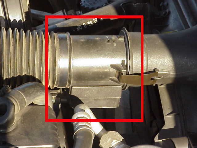
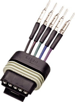
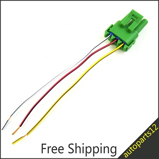
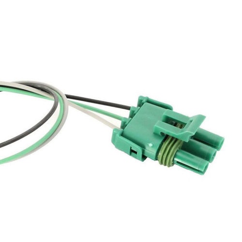
replacement connectors and pigtails are available
http://garage.grumpysperformance.com/index.php?threads/lots-of-wiring-info-diagrams.317/#post-83877
http://garage.grumpysperformance.co...-auto-elecrtrical-connectors.3105/#post-68805
http://garage.grumpysperformance.co...cting-a-distributor-for-your-application.855/
http://garage.grumpysperformance.co...-idles-and-sometimes-stalls.10688/#post-46397
viewtopic.php?f=36&t=3105&p=8272&hilit=connectors+pigtails#p8272
viewtopic.php?f=32&t=168&p=41767&hilit=connectors+pigtails#p41767
http://garage.grumpysperformance.co...lay-switch-locations-and-info.728/#post-17654

http://www.1aauto.com/mass-air-flow..._content=EAF&gclid=CO-WoOWzqMoCFZOCaQod8M0L2A
1985 - 1226870 ECM - Camaros, Firebirds, and Corvettes
Being the first year of production for the TPI system, there were some things that GM wanted to change almost right off the bat. This year was a MAF setup, and used the 1226870 ECM. This was an ECM in the C3 family (like a TBI ECM). This ECM was used only on 1985 models. It used a small box mounted right above the ECM called the Mass Air Burnoff Module. This ECM can be easily recognized by having the PROM access cover at the top of the unit, and has only two harness connectors.
This ECM was used both on 305 and 350 engines. Depending on the engine size however, it used a different PROM, and a different CAL-PAK. There is limited support for this ECM as far as PROM modifications. This does not mean that it is more difficult, or that PROM modifications can't be made. Its just that there hasn't been as large an effort to work on this ECM, enthusiasts often end up converting to a later model ECM. Also, it sends data to the ALDL port at 160 baud, which is very slow. This provides a "snapshot" of what all the sensors are reading once every few seconds. By comparison, the later TPI ECMs were 8192 baud. They sent data several times a second.
I have read on several occassions that late in the 1985 production run, GM had already changed to the ECM and harness that they later used in 1986. I have not confirmed this myself, so I can't say for sure that its true. If this is true though, it is possible though to come across a 1985 model which uses the 86-89 ECM.
1986-1989 - 1227165 ECM - Camaros, Firebirds, and Corvettes
This is the most common ECM which is used on MAF style setups. ECM number 16198259 is equivalent and can be used in its place without any problems. The same computer was used both for 305 and for 350 engines. The only difference between the two engine sizes was the PROM that was used. The Mass Air Burnoff Module that GM used in 1985 is no longer present. This model is part of the P4 ECM family. This ECM can be easily recognized by having the PROM access cover in the center of the unit, and has only two harness connectors.
Support for this ECM with regards to PROMs is much more common. Due to the nature of the MAF sensor, it is very easy to run a large or moderate cam without needing PROM changes. This system is not very sensitive to engine changes, and can adapt fairly well. However, many enthusiasts find that it is a little more difficult to fine tune than the later Speed Density system. Please realize that this is a matter of opinion and personal preference. Each of these systems have advantages and disadvantages over one another. ALDL data is sent at 8192 baud, much faster than the 1985 ECM. This allows for several sets of data per second.
1990-1992 - 1227730 ECM - Camaros and Firebirds
By far the most common ECM used on TPI conversions onto older vehicles. This is the later style Speed Density system. It does not use a Mass Air Flow sensor. Instead, a Manifold Absolute Pressure sensor is used in its place. This allows more flexibility in running air ducts to the throttle body, or an air filter can be installed directly on the throttle body. It is for this reason, that it provides a cleaner looking installation on many street rods, and hot rods. There are two equivalent ECM numbers which can be used in its place without any problems. These are numbers 16196344, and 16198262. This ECM is also in the P4 family. It mounts inside the passenger compartment, as it is not weatherproof. It can be recognized by having a very large PROM access cover that runs from one side of the ECM to the other, and has three harness connectors.
By far the most support for PROM work exists for this ECM. Most enthusiasts feel this is the easiest system to tune. However, it is also very sensitive to engine changes. Any change that affects the engines volumetric efficiency significantly (ability to fill the combustion chamber) will not show its true potential until the system has been tuned. Volumetric efficiency is affected mostly by cam and head changes. This does not mean that you cannot run a moderate or large camshaft with this setup. It only means that tuning is required to see the true potential of engine modifications. This ECM provides ALDL data at 8192 baud as well. This is relatively fast, as it provides several sets of data every second.
This ECM is internally the same as the 1227727. The only difference is that the 1227727 is weatherproof and can be mounted in the engine compartment whereas the 1227730 cannot. The PROMs will interchange between these two computers. Harnesses will not interchange, as the ECM connectors are very different.
1990-1991 - 1227727 ECM - Corvettes
This ECM is internally the same as the 1227730 mentioned above. The difference is that this one is weatherproof and can be mounted in the engine compartment. This is the later style Speed Density system. It does not use a Mass Air Flow sensor. Instead, a Manifold Absolute Pressure sensor is used in its place. This allows more flexibility in running air ducts to the throttle body, or an air filter can be installed directly on the throttle body. It is for this reason, that it provides a cleaner looking installation on many street rods, and hot rods. There are two equivalent ECM numbers which can be used in its place without any problems. These are numbers 16197128, and 16198260. This ECM is also in the P4 family. It can be recognized by the four large ECM connectors.
This ECM as well as the 1227730 can use each others PROMs. Due to this reason, there is plenty of support for PROM work available. Because this is a Speed Density system, most enthusiasts feel this is the easiest system to tune. However, it is also very sensitive to engine changes. Any change that affects the engines volumetric efficiency significantly (ability to fill the combustion chamber) will not show its true potential until the system has been tuned. Volumetric efficiency is affected mostly by cam and head changes. This does not mean that you cannot run a moderate or large camshaft with this setup. It only means that tuning is required to see the true potential of engine modifications. This ECM provides ALDL data at 8192 baud as well. This is relatively fast, as it provides several sets of data every second.
This ECM is internally the same as the 1227730. The only difference is that the 1227730 is not weatherproof and must be mounted inside the passenger compartment. Harnesses will not interchange, as the ECM connectors are very different.
links to info that may help
https://www.themotorbookstore.com/c...MIrei9nJqr7gIVD4iGCh3orQayEAQYAiABEgJUMPD_BwE
http://www.larryselectricsite.com/downloads/tpiinstructions.pdf
https://howellefi.com/wp-content/up...t-or-LT1-Fuel-Injection-Harness-1985-1992.pdf
https://www.hotrodhardware.com/inde...d=7157/category_id=1579/mode=prod/prd7157.htm
https://www.ronfrancis.com/images/TP30-INST.pdf
http://www.jimsperformance.com/tpibuy.html
https://www.hotrodhandbooks.com.au/eBooks/TPI/TPI On Line-03-1.html
you'll really need THAT DETAILED info,
the LINKS AND SUB LINKS
, AND those SUB -SUB LINKS and the info they contain,
so don't skip over reading them carefully.
you'll find many guys claiming that aftermarket CPU chip upgrades help a great deal
Iv'e found some help marginally but many actually hurt performance
http://www.iroc-z.com/articles/articlepages/1990-3Chips Article by Cliff Gromer, Super Stock, 1991.htm
http://tpiparts.net/85_89_maf_sensors/
http://www.1aauto.com/mass-air-flow..._content=EAF&gclid=CO-WoOWzqMoCFZOCaQod8M0L2A
http://garage.grumpysperformance.com/index.php?threads/testing-1985-89-m-a-f-sensor.1475/#post-43635
http://www.eecis.udel.edu/~davis/z28/ecm_swap_730/
http://www.eecis.udel.edu/~davis/z28/ecm_swap/
viewtopic.php?f=36&t=10946
http://tpiparts.net/tech_articles
viewtopic.php?f=80&t=728&p=43477&hilit=camaro+sensors#p43477
viewtopic.php?f=32&t=169
viewtopic.php?f=80&t=2861&p=7410#p7410
viewtopic.php?f=36&t=10567&p=45108#p45108
http://tpiparts.net/305_tpi_to_350_tpi_conversion
http://tpiparts.net/installing_tpi_on_your_vehicle
http://hotrodlane.cc/PDFFILES/TPIStory.pdf
http://www.eecis.udel.edu/~davis/z28/ECMs/86to92.txt
http://tpiparts.net/85_89_maf_sensors/
http://tpiparts.net/90_92_speed_density_sensors/
http://tpiparts.net/retrieving_and_clearing_error_codes
http://tpiparts.net/1227730_pinout_diagram
http://garage.grumpysperformance.co...otal-panic-over-an-easy-fix.12177/#post-58940
read these links and
related sub links
pull trouble codes
http://garage.grumpysperformance.co...oven-facts-if-your-in-doubt.13051/#post-84695
http://forum.grumpysperformance.com/viewtopic.php?f=32&t=1401&p=8895&hilit=start+sequence#p8895
http://garage.grumpysperformance.com/index.php?threads/c4-c5-corvette-trouble-codes.2697/
http://garage.grumpysperformance.com/index.php?threads/lots-of-wiring-info-diagrams.317/#post-83877
http://garage.grumpysperformance.com/index.php?threads/adjusting-your-tps-and-iac.168/
http://garage.grumpysperformance.com/index.php?threads/multi-meters.3110/#post-71867
http://garage.grumpysperformance.com/index.php?threads/1990-corvette-no-spark.13857/#post-70888
http://garage.grumpysperformance.com/index.php?threads/diagnoseing-tpi-lt1-problems.1241/
reading links and sub links can help
replacement connectors and pigtails are available
http://garage.grumpysperformance.com/index.php?threads/lots-of-wiring-info-diagrams.317/#post-83877
http://garage.grumpysperformance.co...-auto-elecrtrical-connectors.3105/#post-68805
http://garage.grumpysperformance.co...cting-a-distributor-for-your-application.855/
http://garage.grumpysperformance.co...-idles-and-sometimes-stalls.10688/#post-46397
viewtopic.php?f=36&t=3105&p=8272&hilit=connectors+pigtails#p8272
viewtopic.php?f=32&t=168&p=41767&hilit=connectors+pigtails#p41767
http://garage.grumpysperformance.co...lay-switch-locations-and-info.728/#post-17654
http://www.1aauto.com/mass-air-flow..._content=EAF&gclid=CO-WoOWzqMoCFZOCaQod8M0L2A
1985 - 1226870 ECM - Camaros, Firebirds, and Corvettes
Being the first year of production for the TPI system, there were some things that GM wanted to change almost right off the bat. This year was a MAF setup, and used the 1226870 ECM. This was an ECM in the C3 family (like a TBI ECM). This ECM was used only on 1985 models. It used a small box mounted right above the ECM called the Mass Air Burnoff Module. This ECM can be easily recognized by having the PROM access cover at the top of the unit, and has only two harness connectors.
This ECM was used both on 305 and 350 engines. Depending on the engine size however, it used a different PROM, and a different CAL-PAK. There is limited support for this ECM as far as PROM modifications. This does not mean that it is more difficult, or that PROM modifications can't be made. Its just that there hasn't been as large an effort to work on this ECM, enthusiasts often end up converting to a later model ECM. Also, it sends data to the ALDL port at 160 baud, which is very slow. This provides a "snapshot" of what all the sensors are reading once every few seconds. By comparison, the later TPI ECMs were 8192 baud. They sent data several times a second.
I have read on several occassions that late in the 1985 production run, GM had already changed to the ECM and harness that they later used in 1986. I have not confirmed this myself, so I can't say for sure that its true. If this is true though, it is possible though to come across a 1985 model which uses the 86-89 ECM.
1986-1989 - 1227165 ECM - Camaros, Firebirds, and Corvettes
This is the most common ECM which is used on MAF style setups. ECM number 16198259 is equivalent and can be used in its place without any problems. The same computer was used both for 305 and for 350 engines. The only difference between the two engine sizes was the PROM that was used. The Mass Air Burnoff Module that GM used in 1985 is no longer present. This model is part of the P4 ECM family. This ECM can be easily recognized by having the PROM access cover in the center of the unit, and has only two harness connectors.
Support for this ECM with regards to PROMs is much more common. Due to the nature of the MAF sensor, it is very easy to run a large or moderate cam without needing PROM changes. This system is not very sensitive to engine changes, and can adapt fairly well. However, many enthusiasts find that it is a little more difficult to fine tune than the later Speed Density system. Please realize that this is a matter of opinion and personal preference. Each of these systems have advantages and disadvantages over one another. ALDL data is sent at 8192 baud, much faster than the 1985 ECM. This allows for several sets of data per second.
1990-1992 - 1227730 ECM - Camaros and Firebirds
By far the most common ECM used on TPI conversions onto older vehicles. This is the later style Speed Density system. It does not use a Mass Air Flow sensor. Instead, a Manifold Absolute Pressure sensor is used in its place. This allows more flexibility in running air ducts to the throttle body, or an air filter can be installed directly on the throttle body. It is for this reason, that it provides a cleaner looking installation on many street rods, and hot rods. There are two equivalent ECM numbers which can be used in its place without any problems. These are numbers 16196344, and 16198262. This ECM is also in the P4 family. It mounts inside the passenger compartment, as it is not weatherproof. It can be recognized by having a very large PROM access cover that runs from one side of the ECM to the other, and has three harness connectors.
By far the most support for PROM work exists for this ECM. Most enthusiasts feel this is the easiest system to tune. However, it is also very sensitive to engine changes. Any change that affects the engines volumetric efficiency significantly (ability to fill the combustion chamber) will not show its true potential until the system has been tuned. Volumetric efficiency is affected mostly by cam and head changes. This does not mean that you cannot run a moderate or large camshaft with this setup. It only means that tuning is required to see the true potential of engine modifications. This ECM provides ALDL data at 8192 baud as well. This is relatively fast, as it provides several sets of data every second.
This ECM is internally the same as the 1227727. The only difference is that the 1227727 is weatherproof and can be mounted in the engine compartment whereas the 1227730 cannot. The PROMs will interchange between these two computers. Harnesses will not interchange, as the ECM connectors are very different.
1990-1991 - 1227727 ECM - Corvettes
This ECM is internally the same as the 1227730 mentioned above. The difference is that this one is weatherproof and can be mounted in the engine compartment. This is the later style Speed Density system. It does not use a Mass Air Flow sensor. Instead, a Manifold Absolute Pressure sensor is used in its place. This allows more flexibility in running air ducts to the throttle body, or an air filter can be installed directly on the throttle body. It is for this reason, that it provides a cleaner looking installation on many street rods, and hot rods. There are two equivalent ECM numbers which can be used in its place without any problems. These are numbers 16197128, and 16198260. This ECM is also in the P4 family. It can be recognized by the four large ECM connectors.
This ECM as well as the 1227730 can use each others PROMs. Due to this reason, there is plenty of support for PROM work available. Because this is a Speed Density system, most enthusiasts feel this is the easiest system to tune. However, it is also very sensitive to engine changes. Any change that affects the engines volumetric efficiency significantly (ability to fill the combustion chamber) will not show its true potential until the system has been tuned. Volumetric efficiency is affected mostly by cam and head changes. This does not mean that you cannot run a moderate or large camshaft with this setup. It only means that tuning is required to see the true potential of engine modifications. This ECM provides ALDL data at 8192 baud as well. This is relatively fast, as it provides several sets of data every second.
This ECM is internally the same as the 1227730. The only difference is that the 1227730 is not weatherproof and must be mounted inside the passenger compartment. Harnesses will not interchange, as the ECM connectors are very different.
links to info that may help
https://www.themotorbookstore.com/c...MIrei9nJqr7gIVD4iGCh3orQayEAQYAiABEgJUMPD_BwE
http://www.larryselectricsite.com/downloads/tpiinstructions.pdf
https://howellefi.com/wp-content/up...t-or-LT1-Fuel-Injection-Harness-1985-1992.pdf
https://www.hotrodhardware.com/inde...d=7157/category_id=1579/mode=prod/prd7157.htm
https://www.ronfrancis.com/images/TP30-INST.pdf
http://www.jimsperformance.com/tpibuy.html
https://www.hotrodhandbooks.com.au/eBooks/TPI/TPI On Line-03-1.html
Last edited by a moderator: